


MD-6XP
INSTALLATION AND OPERATION MANUAL
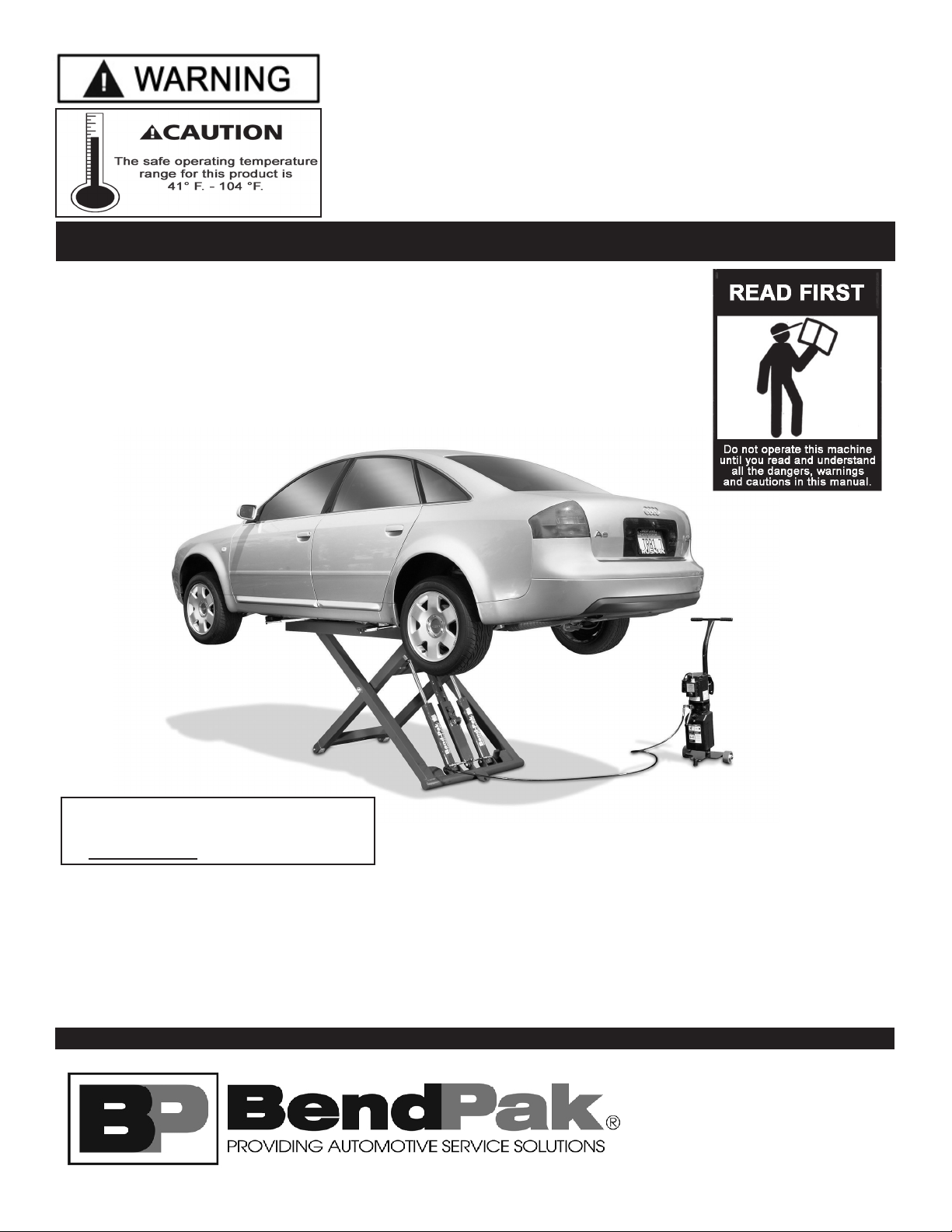
6,000 POUND CAPACITY
PORTABLE MID RISE LIFT
MODEL: MD-6XP
PLEASE READ THE ENTIRE CONTENTS OF THIS MANUAL PRIOR TO
INSTALLATION AND OPERATION. BY PROCEEDING YOU AGREE THAT
YOU FULLY UNDERSTAND AND COMPREHEND THE FULL CONTENTS OF
THIS MANUAL. FORWARD THIS MANUAL TO ALL OPERATORS. FAILURE TO
OPERATE THIS EQUIPMENT AS DIRECTED MAY CAUSE INJURY OR DEATH.
REV E 08-08-2012
p/n 5900108
Keep this operation manual near the
machine at all times. Make sure that
ALL USERS read this manual.
SHIPPING DAMAGE CLAIMS
When this equipment is shipped, title passes to the
purchaser upon receipt from the carrier. Consequently,
claims for the material damaged in shipment
must be made by the purchaser against the
transportation company at the time shipment is received.
BE SAFE
Your new lift was designed and built with safety in mind.
However, your overall safety can be increased by proper
training and thoughtful operation on the part of the operator.
DO NOT operate or repair this equipment without reading this
manual and the important safety instructions shown inside.
1645 Lemonwood Dr.
Santa Paula, CA. 93060, USA
Toll Free 1-800-253-2363
Tel: 1-805-933-9970
Fax: 1-805-933-9160
www.bendpak.com
6,000 POUND CAPACITY
MID RISE LIFT
This instruction manual has been prepared especially for you.
Your new lift is the product of over 35 years of continuous research, testing and development;
it is the most technically advanced lift on the market today.
READ THIS ENTIRE MANUAL BEFORE INSTALLATION & OPERATION BEGINS.
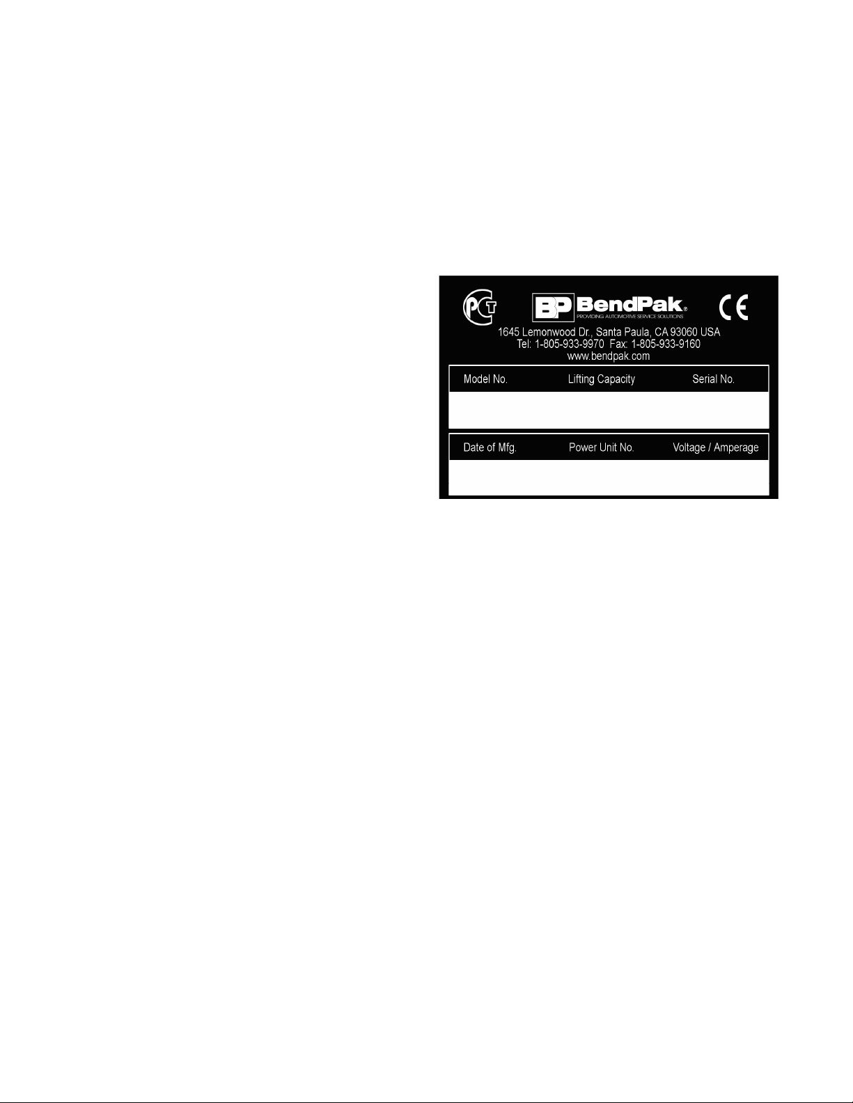
RECORD HERE THE LIFT AND
POWER UNIT INFORMATION WHICH IS
LOCATED ON THE SERIAL NUMBER
DATA PLATES ON THE LIFT AND
ON THE POWER UNIT
Power Unit Model # _____________
Power Unit Date Of Mfg. _____________
Power Unit Serial # _____________
This information is required when
calling for parts or warranty issues.
PRODUCT WARRANTY
BendPak Mid Rise Lifts are covered under warranty for one year on equipment structure, to be free of defects in
material and workmanship. Power units, hydraulic cylinders, and all other assembly components such as turnplates,
slip plates, cables, chains, valves, switches etc. are covered under warranty for one year against defects in material or
workmanship under normal use. BendPak Inc. shall repair or replace at their option for the warranty period those parts
returned to the factory freight prepaid which prove upon inspection to be defective. BendPak Inc. will pay labor costs for
the first 12 months only on parts returned as previously described.
The warranty does not extend to...
t defects caused by ordinary wear, abuse, misuse, shipping damage, improper
installation, voltage or lack of required maintenance;
t damages resulting from purchaser’s neglect or failure to operate products in accordance with
instructions provided in the owner’s manuals) and/or other accompanying instructions supplied;
t normal wear items or service normally required to maintain the product in a safe operating condition;
t any component damaged in shipment;
t other items not listed but may be considered general wear parts;
t damage caused by rain, excessive humidity, corrosive environments or other contaminants.
THESE WARRANTIES DO NOT EXTEND TO ANY COSMETIC DEFECT NOT INTERFERING WITH EQUIPMENT
FUNCTIONALITY OR ANY INCIDENTAL, INDIRECT, OR CONSEQUENTIAL LOSS, DAMAGE, OR EXPENSE THAT
MAY RESULT FROM ANY DEFECT, FAILURE, OR MALFUNCTION OF A BENDPAK INC. PRODUCT OR THE
BREACH OR DELAY IN PERFORMANCE OF THE WARRANTY.
WARRANTY IS NOT VALID UNLESS
WARRANTY CARD IS RETURNED.
2
IMPORTANT NOTICE
Do not attempt to install this lift if you have never been
trained on basic automotive lift installation procedures.
Never attempt to lift components without proper lifting
tools such as forklift or cranes. Stay clear of any moving
parts that can fall and cause injury. These instructions
must be followed to ensure proper installation and
operation of your lift. Failure to comply with these
instructions can result in serious bodily harm and void
product warranty. Manufacturer will assume no liability for
loss or damage of any kind, expressed or implied
resulting from improper installation or use of this product.
PLEASE READ ENTIRE MANUAL
PRIOR TO INSTALLATION.
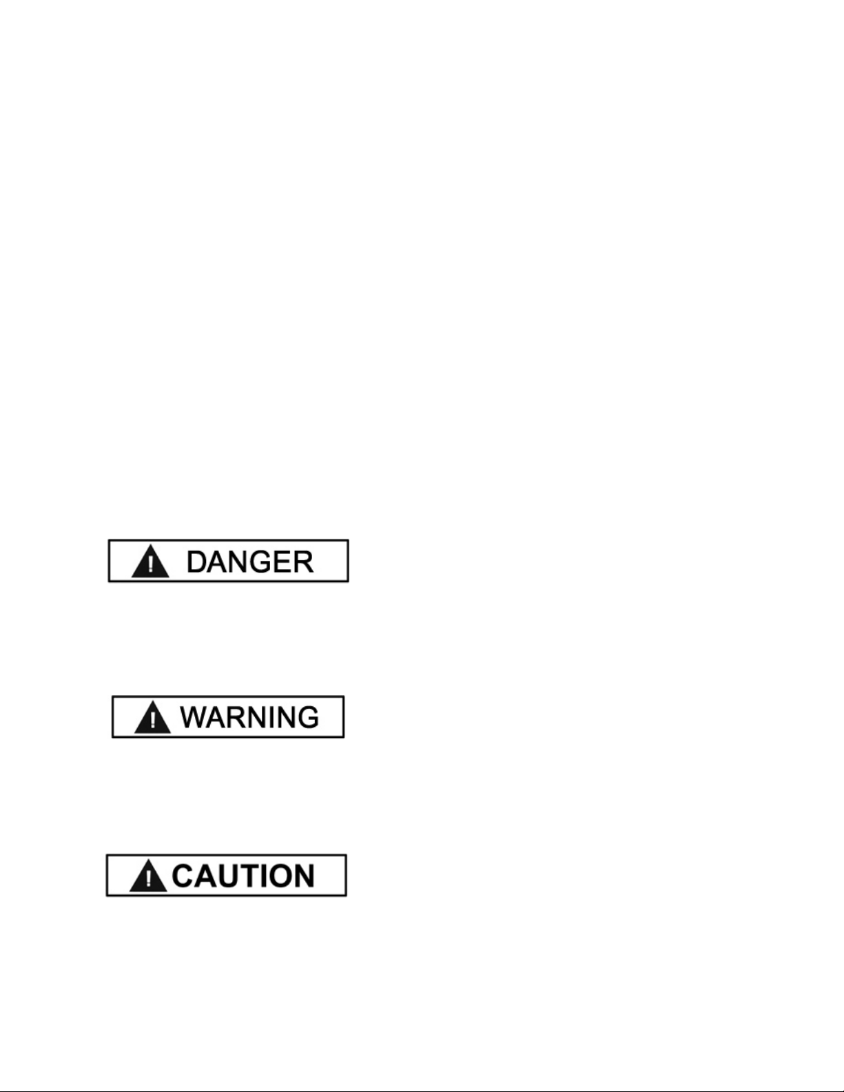
DEFINITIONS OF
HAZARD LEVELS
Identify the hazard levels used in this manual with the
following definitions and signal words:
OWNER’S RESPONSIBILITY
To maintain the lift and user safety, the responsibility of
the owner is to read and follow these instructions:
tFollow all installation and operation instructions.
tMake sure installation conforms to all applicable Local,
State, and Federal Codes, Rules, and Regulations;
such as State and Federal OSHA Regulations and
Electrical Codes.
tCarefully check the lift for correct initial function.
t Read and follow the safety instructions. Keep them
readily available for machine operators.
tMake certain all operators are properly trained, know
how to safely and correctly operate the unit, and are
properly supervised.
tAllow unit operation only with all parts in place and
operating safely.
t Carefully inspect the unit on a regular basis and
perform all maintenance as required.
tService and maintain the unit only with authorized or
approved replacement parts.
tKeep all instructions permanently with the unit and
all decals on the unit clean and visible.
DANGER !
Watch for this symbol: It Means: Immediate hazards
which will result in severe personal injury or death.
WARNING !
Watch for this symbol: It Means: Hazards or unsafe
practices which could result in severe personal
injury or death.
CAUTION !
Watch for this symbol: It Means: Hazards or unsafe
practices which may result in minor personal injury,
product or property damage.
BEFORE YOU BEGIN
Receiving:
The shipment should be thoroughly inspected as soon as it
is received. The signed bill of lading is acknowledgement by
the carrier of receipt in good condition of shipment covered
by your invoice. If any of the goods called for on this bill of
lading are shorted or damaged, do not accept them until the
carrier makes a notation on the freight bill of the shorted or
damaged goods. Do this for your own protection.
NOTIFY THE CARRIER AT ONCE if any hidden loss or
damage is discovered after receipt and request the carrier
to make an inspection. If the carrier will not do so, prepare
a signed statement to the effect that you have notified the
carrier (on a specific date) and that the carrier has failed to
comply with your request.
IT IS DIFFICULT TO COLLECT FOR LOSS OR DAMAGE
AFTER YOU HAVE GIVEN THE CARRIER A CLEAR
RECEIPT. File your claim with the carrier promptly. Support
your claim with copies of the bill of lading, freight bill,
invoice, and photographs, if available. Our willingness to
assist in helping you process your claim does not make
BendPak responsible for collection of claims or
replacement of lost or damaged materials.
3

TABLE OF CONTENTS
Contents Page No.
Warranty / Serial Number Information . . . . . . . . . . . . . . . . . . . . . . . . . . . . . . . . . . . . . . . . . . . . . . . . . . . . . . . . . . . . . 2
Definitions of Hazard Levels . . . . . . . . . . . . . . . . . . . . . . . . . . . . . . . . . . . . . . . . . . . . . . . . . . . . . . . . . . . . . . . . . . . . .3
Owner’s Responsibility . . . . . . . . . . . . . . . . . . . . . . . . . . . . . . . . . . . . . . . . . . . . . . . . . . . . . . . . . . . . . . . . . . . . . . . . .3
Before You Begin . . . . . . . . . . . . . . . . . . . . . . . . . . . . . . . . . . . . . . . . . . . . . . . . . . . . . . . . . . . . . . . . . . . . . . . . . . . . 3
Table Of Contents . . . . . . . . . . . . . . . . . . . . . . . . . . . . . . . . . . . . . . . . . . . . . . . . . . . . . . . . . . . . . . . . . . . . . . . . . . . . 4
Installer / Operator Instructions . . . . . . . . . . . . . . . . . . . . . . . . . . . . . . . . . . . . . . . . . . . . . . . . . . . . . . . . . . . . . . . . . . 5
Safety / Warning Instructions . . . . . . . . . . . . . . . . . . . . . . . . . . . . . . . . . . . . . . . . . . . . . . . . . . . . . . . . . . . . . . . . . . . 6
Tools Required . . . . . . . . . . . . . . . . . . . . . . . . . . . . . . . . . . . . . . . . . . . . . . . . . . . . . . . . . . . . . . . . . . . . . . . . . . . . . .7
Step 1 / Selecting Site . . . . . . . . . . . . . . . . . . . . . . . . . . . . . . . . . . . . . . . . . . . . . . . . . . . . . . . . . . . . . . . . . . . . . . . . .7
Step 2 / Floor Requirements . . . . . . . . . . . . . . . . . .. . . . . . . . . . . . . . . . . . . . . . . . . . . . . . . . . . . . . . . . . . . . . . . . . . .7
Concrete Specifications . . . . . . . . . . . . . . . . . . . . . . . . . . . . . . . . . . . . . . . . . . . . . . . . . . . . . . . . . . . . . . . . . . . . . . . 7
Assembly View / Description of Parts . . . . . . . . . . . . . . . . . . . . . . . . . . . . . . . . . . . . . . . . . . . . . . . . . . . . . . . . . . . . . . 8
Floor Plan / Specifications . . . . . . . . . . . . . . . . . . . . . . . . . . . . . . . . . . . . . . . . . . . . . . . . . . . . . . . . . . . . . . . . . . . . . .9
Step 3 / Power Unit Set Up . . . . . . . . . . . . . . . . . . . . . . . . . . . . . . . . . . . . . . . . . . . . . . . . . . . . . . . . . . . . . . . . . . . .10
Step 4 / Connecting Hydraulic Hoses Fittings . . . . . . . . . . . . . . . . . . . . . . . . . . . . . . . . . . . . . . . . . . . . . . . . . . . . . . 10
Step 5 / Lift Arm Installation . . . . . . . . . . . . . . . . . . . . . . . . . . . . . . . . . . . . . . . . . . . . . . . . . . . . . . . . . . . . . . . . . . . .11
Step 6 / Installing/ Changing Lift Pads . . . . . . . . . . . . . . . . . . . . . . . . . . . . . . . . . . . . . . . . . . . . . . . . . . . . . . . . . . . . 11
Step 7 / Wiring Power Unit . . . . . . . . . . . . . . . . . . . . . . . . . . . . . . . . . . . . . . . . . . . . . . . . . . . . . . . . . . . . . . . . . . . . .12
Step 8 / Lift Start Up / Final Adjustments . . . . . . . . . . . . . . . . . . . . . . . . . . . . . . . . . . . . . . . . . . . . . . . . . . . . . . . . . .14-15
Step 9 Bleeding . . . . . . . . . . . . . . . . . . . . . . . . . . . . . . . . . . . . . . . . . . . . . . . . . . . . . . . . . . . . . . . . . . . . . . . . . . . . .15
Post Installation Check-Off . . . . . . . . . . . . . . . . . . . . . . . . . . . . . . . . . . . . . . . . . . . . . . . . . . . . . . . . . . . . . . . . . . . 15
Step 10 / Operation/ Maintenance . . . . . . . . . . . . . . . . . . . . . . . . . . . . . . . . . . . . . . . . . . . . . . . . . . . . . . . . . . . . .16-25
Troubleshooting Guide . . . . . . . . . . . . . . . . . . . . . . . . . . . . . . . . . . . . . . . . . . . . . . . . . . . . . . . . . . . . . . . . . . . . . 26-29
Parts Breakdown . . . . . . . . . . . . . . . . . . . . . . . . . . . . . . . . . . . . . . . . . . . . . . . . . . . . . . . . . . . . . . . . . . . . . . . . . . 30-32
Maintenance Records . . . . . . . . . . . . . . . . . . . . . . . . . . . . . . . . . . . . . . . . . . . . . . . . . . . . . . . . . . . . . . . . . . . . . . 33-34
4

INSTALLER / OPERATOR
PLEASE READ AND FULLY
UNDERSTAND.
BY PROCEEDING YOU AGREE TO
THE FOLLOWING.
tI have visually inspected the site where the lift is to be
installed and verified the concrete to be in good
condition and free of cracks or other defects. I understand
that installing a lift on cracked or defective concrete could
cause lift failure resulting in personal injury or death.
t I understand that a level floor is required for proper
installation and level lifting.
t I understand that I am responsible if my floor is of
questionable slope and that I will be responsible for all
charges related to pouring a new level concrete slab if
required and any charges.
t I understand that the lifts are supplied with concrete
fasteners meeting the criteria of the American National
Standard “Automotive Lifts - Safety Requirements for
Construction, Testing, and Validation” ANSI/ALI ALCTV2006, and that I will be responsible for all charges related
to any special regional structural and/or seismic
anchoring requirements specified by any other agencies
and/or codes such as the Uniform Building Code (UBC)
and/or International Building Code (IBC).
t I will assume full responsibility for the concrete floor
and condition thereof, now or later, where the above
equipment model(s) are to be installed. Failure to follow
danger, warning, and caution instructions may lead to
serious personal injury or death to operator or bystander
or damage to property.
t I understand that BendPak lifts are designed to be
installed in indoor locations only. Failure to follow
installation instructions may lead to serious personal
injury or death to operator or bystander or damage to
property or lift.
Failure to follow danger, warning, and caution
instructions may lead to serious personal injury or death
to operator or bystander or damage to property.
Please read entire manual prior to installation.
Do not operate this machine until you read and
understand all the dangers, warnings and cautions
in this manual. For additional copies
or further information, contact:
BendPak Inc. / Ranger Products
1645 Lemonwood Dr.
Santa Paula, CA. 93060
1-805-933-9970
www.bendpak.com
INSTALLER / OPERATOR
PROTECTIVE EQUIPMENT
Personal protective equipment helps makes installation
and operation safer, however, it does not take the place
of safe operating practices. Always wear durable work
clothing during any installation and/or service activity.
Shop aprons or shop coats may also be worn, however
loose fitting clothing should be avoided. Tight fitting
leather gloves are recommended to protect technician
hands when handling parts. Sturdy leather work shoes
with steel toes and oil resistant soles should be used by
all service personnel to help prevent injury during typical
installation and operation activities.
Eye protection is essential during installation and operation
activities. Safety glasses with side shields,
goggles, or face shields are acceptable.
Back belts provide support during lifting
activities and are also helpful in providing
worker protection. Consideration should
also be given to the use of hearing protection if service
activity is performed in an enclosed area, or if noise levels
are high.
THIS SYMBOL POINTS OUT IMPORTANT SAFETY INSTRUCTIONS WHICH IF NOT FOLLOWED
COULD ENDANGER THE PERSONAL SAFETY AND/OR PROPERTY OR YOURSELF AND OTHERS
AND CAN CAUSE PERSONAL INJURY OR DEATH. READ AND FOLLOW ALL INSTRUCTIONS IN
THIS MANUAL BEFORE ATTEMPTING TO OPERATE THIS MACHINE.
5
INTRODUCTION
1. Carefully remove the crating and packing
materials. CAUTION! Be careful when cutting steel
banding material as items may become loose and fall
causing personal harm or injury.
2. Check the voltage, phase and proper amperage
requirements for the motor shown on the motor plate.
Wiring should be performed by a certified electrician
only.
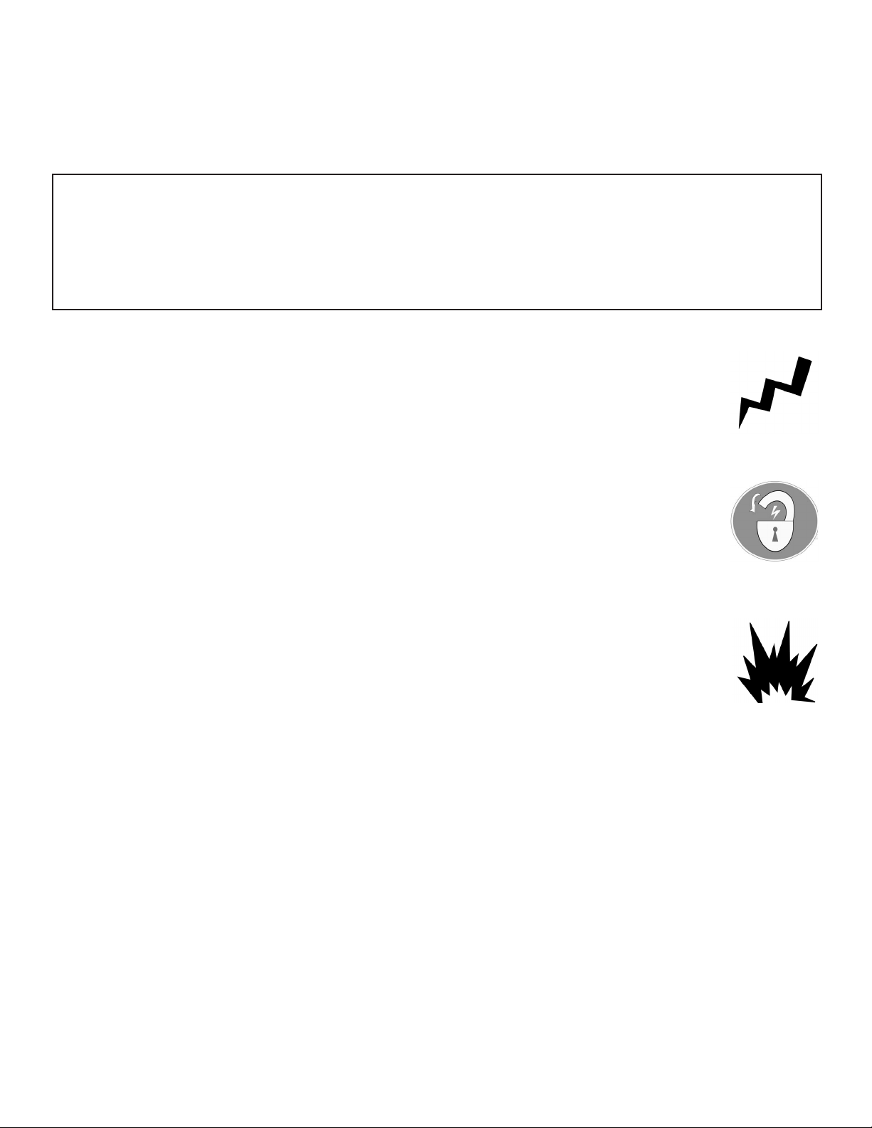
IMPORTANT SAFETY INSTRUCTIONS !
Read these safety instructions entirely!
IMPORTANT NOTICE !
Do not attempt to install this lift if you have never been trained on basic automotive lift installation procedures.
Never attempt to lift components without proper lifting tools such as forklift or cranes.
Stay clear of any moving parts that can fall and cause injury.
1. READ AND UNDERSTAND all safety warning
procedures before operating lift.
2. KEEP HANDS AND FEET CLEAR. Remove hands and
feet from any moving parts. Keep feet clear of lift when
lowering. Avoid pinch points.
3. KEEP WORK AREA CLEAN. Cluttered work areas
invite injuries.
4. Consider work area environment. Do not expose
equipment to rain. DO NOT use in damp or wet locations.
Keep area well lighted.
5. ONLY TRAINED OPERATORS should operate this lift.
All non-trained personnel should be kept away from work
area. Never let non-trained personnel come in contact with,
or operate lift.
12. GUARD AGAINST ELECTRIC SHOCK. This lift must
be grounded while in use to protect the
operator from electric shock. Never connect
the green power cord wire to a live terminal.
This is for ground only.
13. DANGER! The power unit used on this lift contains high
voltage. Disconnect power at the receptacle
before performing any electrical repairs.
Secure plug so that it cannot be
accidentally plugged in during service.
14. WARNING! RISK OF EXPLOSION. This equipment
has internal arcing or sparking parts which
should not be exposed to flammable vapors.
This machine should not be located in a
recessed area or below floor level.
6. USE LIFT CORRECTLY. Use lift in the proper manner.
Never use lifting adapters other than what is approved by the
manufacturer.
7. DO NOT override self-closing lift controls.
8. REMAIN CLEAR of lift when raising or lowering vehicle.
9. CLEAR AREA if vehicle is in danger of falling.
10. ALWAYS ENSURE that the safeties are engaged before
any attempt is made to work on or near vehicle.
11. DRESS PROPERLY. Non-skid steel-toe footwear is
recommended when operating lift.
15. MAINTAIN WITH CARE. Keep lift clean for better and
safer performance. Follow manual for proper lubrication
and maintenance instructions. Keep control handles and/or
buttons dry, clean and free from grease and oil.
16. STAY ALERT. Watch what you are doing. Use common
sense. Be aware.
17. CHECK FOR DAMAGED PARTS. Check for alignment
of moving parts, breakage of parts or any condition that may
affect its operation. Do not use lift if any component is broken
or damaged.
18. NEVER remove safety related components from the lift.
Do not use lift if safety related components are damaged
or missing.
6
TOOLS REQUIRED
t4 Foot Level
tSmall Adjustable Wrench
tLarge Adjustable Wrench
t12mm Hex Key
IMPORTANT NOTICE !
These instructions must be followed to ensure proper installation and operation of your lift.
Failure to comply with these instructions can result in serious bodily harm and void product warranty.
Manufacturer will assume no liability for loss or damage of any kind, expressed or implied resulting
from improper installation or use of this product.
PLEASE READ ENTIRE MANUAL PRIOR TO INSTALLATION !
STEP 1
(Selecting Site)
Before installing your new lift, check the following.
1. LIFT LOCATION: Always use architects plans when
available. Check layout dimension against floorplan
requirements making sure that adequate space if avail-
able.
2. OVERHEAD OBSTRUCTIONS: The area where the
lift will be located should be free of overhead obstruc-
tions such as heaters, building supports, electrical lines
etc.
3. DEFECTIVE FLOOR: Visually inspect the site where
the lift is to be installed and check for cracked or defec-
tive concrete.
A level floor is suggested for proper use and installation and level lifting. If a floor is of questionable slope,
consider a survey of the site and/or the possibility of pouring a new level concrete slab.
t DO NOT install or use this lift on any asphalt surface
or any surface other than concrete.
t DO NOT install or use this lift on expansion seams
or on cracked or defective concrete.
t DO NOT install or use this lift on a second / elevated
floor without first consulting building architect.
t DO NOT install or use this lift outdoors.
4. OPERATING TEMPERATURE. Operate lift only
between temperatures of 41° -104° F.
5. Lift is designed for INDOOR INSTALLATION ONLY.
STEP 2
(Floor Requirements)
This lift must be installed on a solid level concrete
floor with no more than 3-degrees of slope. Failure
to do so could cause personal injury or death.
CONCRETE SPECIFICATIONS
LIFT MODEL CONCRETE REQUIREMENTS
MD-6XP 3.5” Min. Thickness / 2,500 PSI
DANGER!
All models MUST be installed on 3,000 PSI concrete only
conforming to the minimum requirements shown above.
New concrete must be adequately cured by at least
28 days minimum.
7
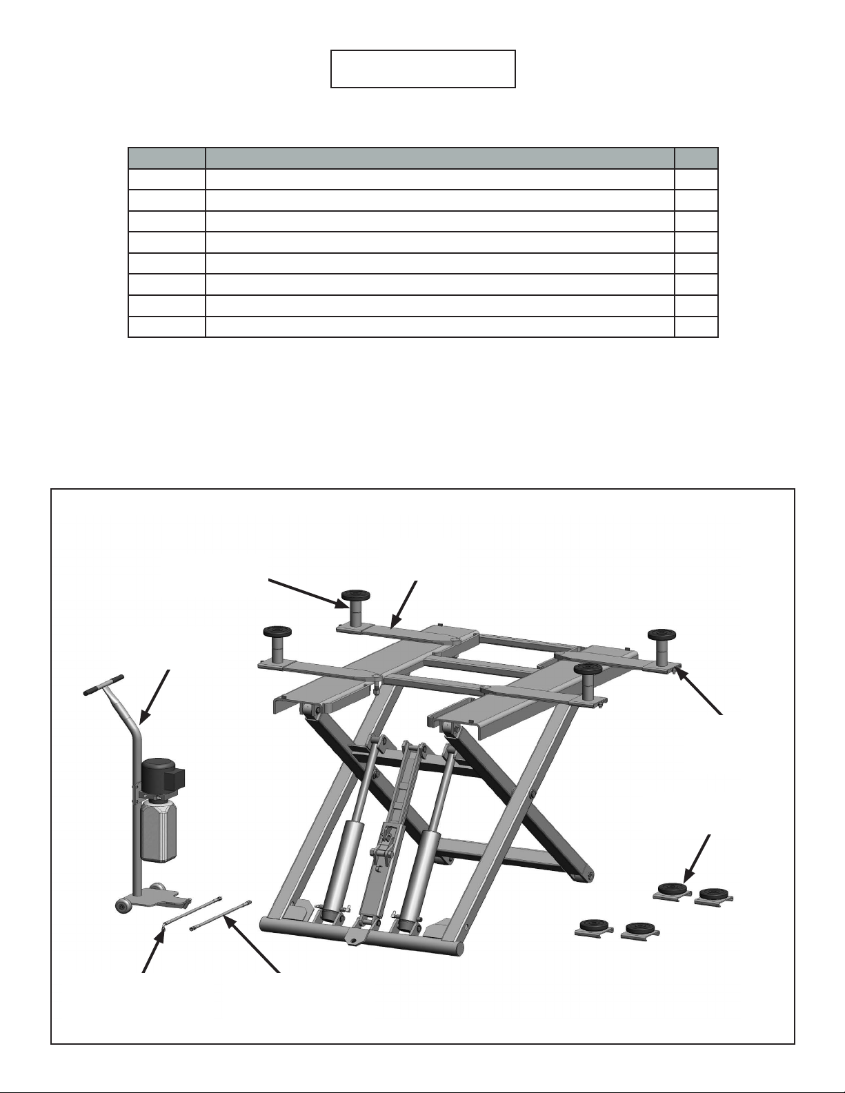
Assembly View
PART # DESCRIPTION QTY
5215264 LIFT ARM ASSEMBLY 4
5215252 SHORT LIFT PAD ASSEMBLY 4
5600257 LIFT PAD WELDMENT BASE 4
5746390 SHORT LIFT PAD EXTENSION (113mm LG.) 4
5570013 HOSE ASSEMBLY Ø6.4 x 3660mm SB 1
5570054 HOSE ASSEMBLY Ø6.4 x 540mm DS 1
5585094 Power Unit AB-1380; 110 / 220 Volt, 60HZ, 1 Phase* 1
5215263 POWER UNIT STAND ASSEMBLY 1
Short Lift Pad
Extension
Power Unit
Stand Assembly
Lift Arm
Assembly
Lift Pad
Weldment
Base
Short Lift Pad
Assembly
Hose Assembly
Ø6.4 x 3660mm SB
Hose Assembly
Ø6.4 x 540mm DS
8
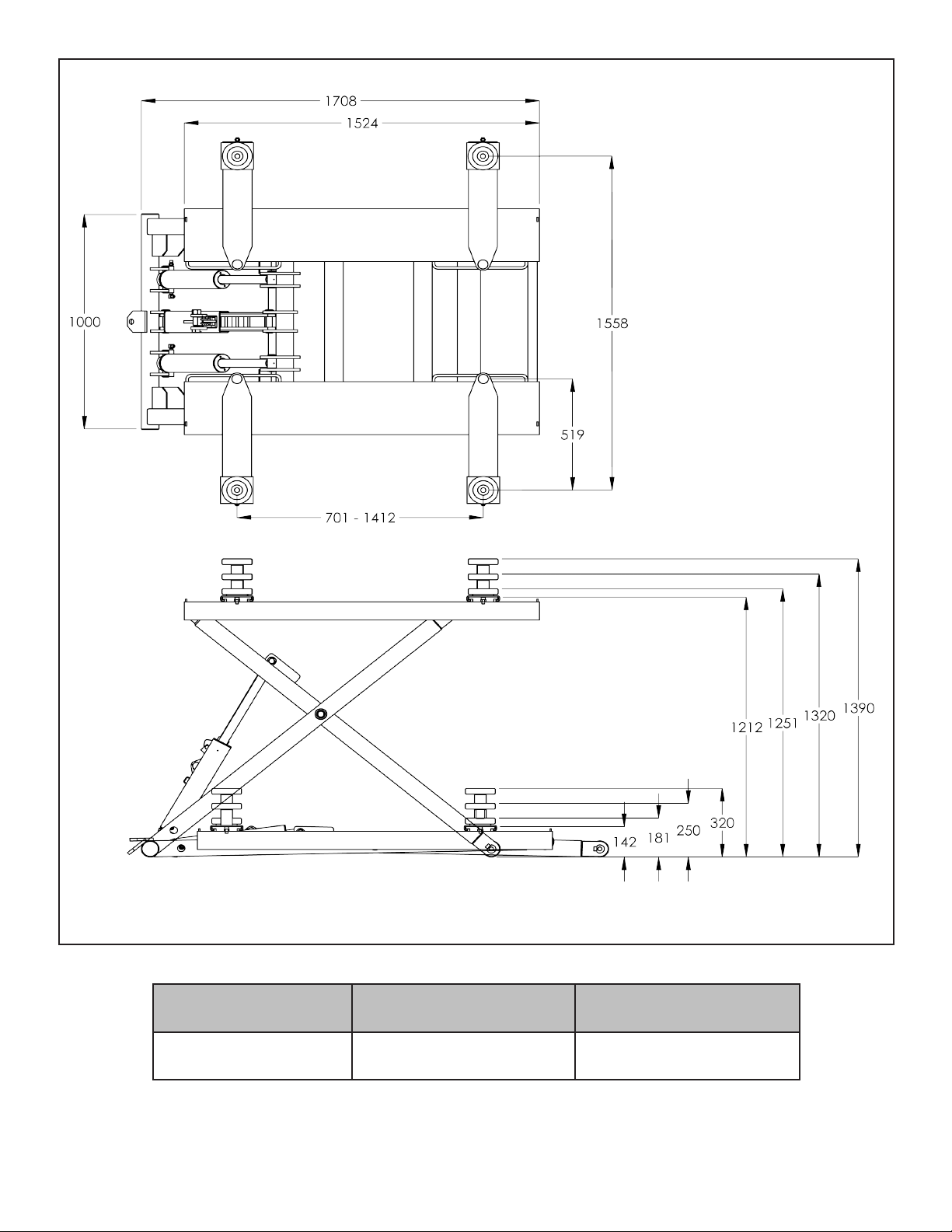
Lifting Capacity Lifting Time Power Unit
6,000 Lbs. / 2721 Kgs. 45 Sec.
*Must specify at time of ordering.
110/220VAC
50/60HZ *
9
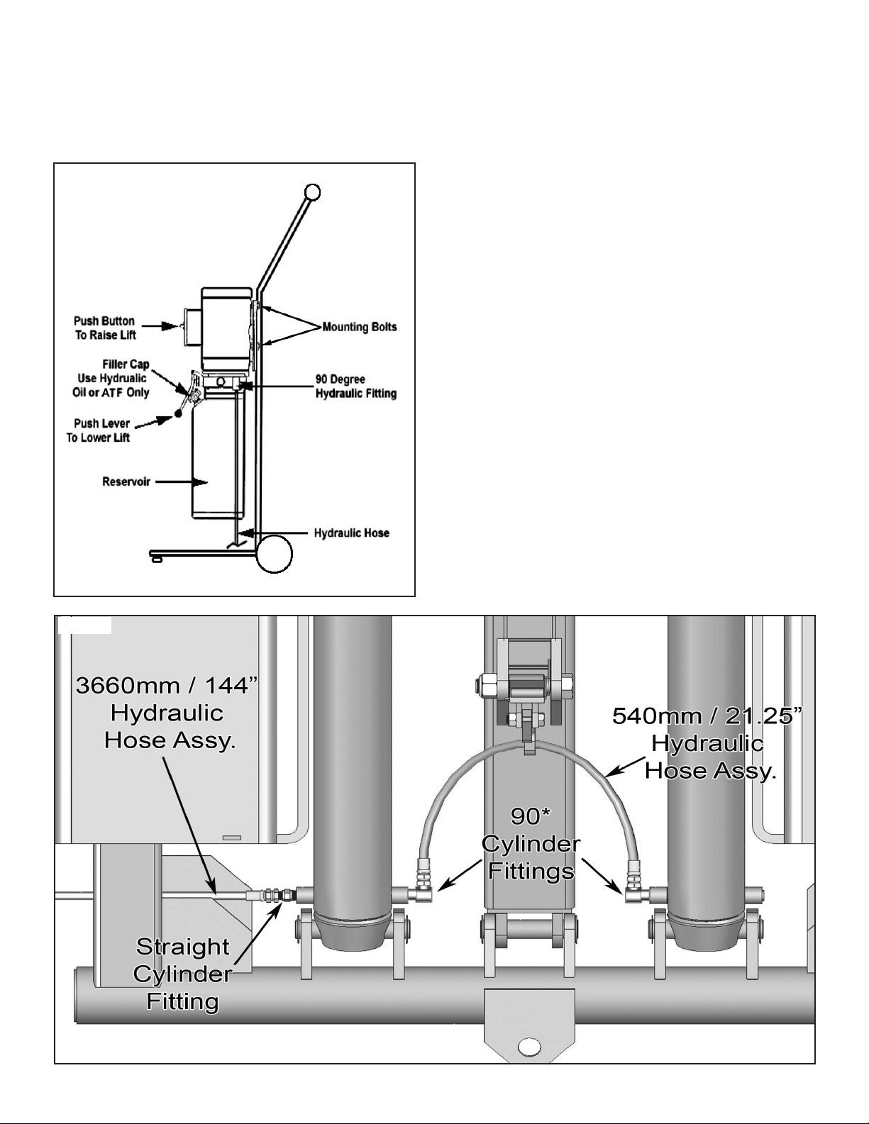
STEP 3
(Power Unit Set Up)
2. Remove plug from power unit and install the 90°
Fitting w/ O-ring into the power port on the Power Unit.
Take care to make sure the O-ring seats properly.
1. Set the Power Unit on the Stand/Tow Handle and
mount using the four M8 x 1.25 x 20mm Bolts, Nuts and
Washers. (See Fig 3.1)
Fig 3.1
3. Connect the 144” Hydraulic Hose to the 90° Fitting.
4. Fill the reservoir with 6 Quarts/ 1.5 gals of Dexron III
ATF or 10W Non-foaming hydraulic fluid.
STEP 4
(Connecting Hydraulic Fittings / Hoses)
1. Remove the plastic plug from the left port of the left
hand Cylinder.
2. Install the Straight Hydraulic Fitting in the left port of
the left hand Cylinder. Use Teflon tape on the Cylinder
side on the Fitting only.
3. Attach the 144” Hydraulic Hose to the Straight
Fitting in the port of the left hand side Cylinder.
4. Check the 21.25” Hose connections and 90* Fittings
on the right side of the left side Cylinder Fitting. Then
check the other end of the 21.25” Hose and 90° Fitting on
the left fitting side of the right hand Cylinder.
5. The right side hydraulic port of the right Cylinder
should be plugged with a metal plug. Check plug and
tighten if necessary. (See Fig 4.1)
Fig 4.1.
10
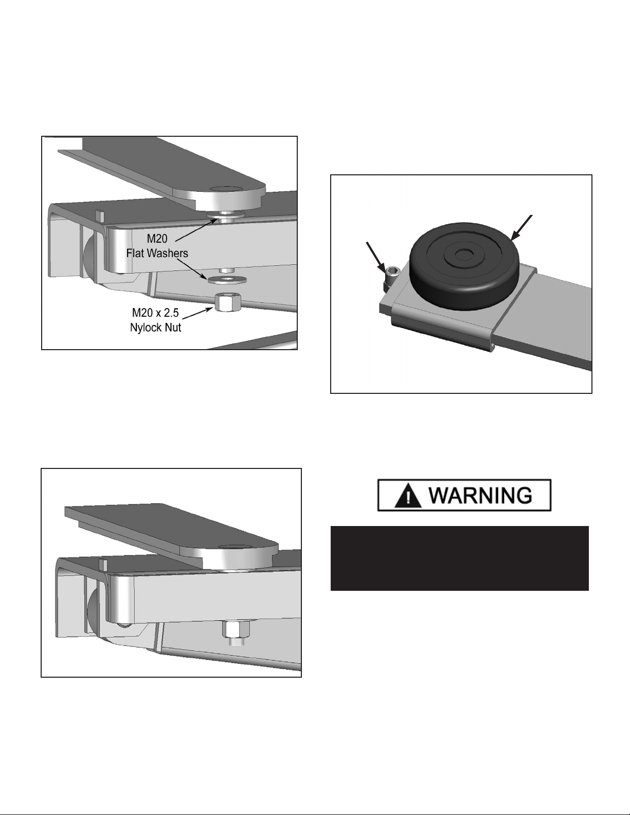
STEP 5
(Lift Arm Installation)
STEP 6
(Installing / Changing Lift Pads)
1. Set the Adjustable Arm on the Ramp ensuring that the
Bolt on the arm is inserted through the arm holder channel
on the side of the ramp. (See Fig. 5.1)
Fig 5.1
1. Remove the Socket Head Screw from the end of the lift
arm.
2. Slide the desired height Lift Pad riser onto the lift arm.
Replace and tighten the Socket head Screw. Drop in the Lift
Pad if applicable. (See Fig.3.)
Fig 6.1
Lift Pad As-
sembly
M12 x 1.75 x
20mm Screw
3. Tighten the M-20-10 nut until the arm cannot pivot, then
back the nut off until the arm is just loose enough to pivot
freely. (See Fig.5.2)
Fig 5.2
Repeat the above procedure for the other three arms.
4. Use the 3” Lift Pad Extension as necessary to reach
proper lifting points on the vehicle.
WARNING!
ALWAYS set the adjustable arms and pads under the
proper lifting points as indicated in the Lifting Guide or
owners manual of the vehicle.
11
 Loading...