

Page 1

Bendix™ VORAD® VS-400
Installation Guide
Bendix™ VORAD® VS-400 System
BW2772 (Formerly VOIG0100)
September 2010
Page 2

Table of Contents
Introduction
Warnings. . . . . . . . . . . . . . . . . . . . . . . . . . . . . . . . . . . . . . . . . . . . . . . . . . . . . . . . . . . . . . . . . . . . . . . . . . . . . . . . . . . . . . . . . . . . . . . . . .2
Federal Communications Commission. . . . . . . . . . . . . . . . . . . . . . . . . . . . . . . . . . . . . . . . . . . . . . . . . . . . . . . . . . . . . . . . . . . . . . . . . . .3
Application Information. . . . . . . . . . . . . . . . . . . . . . . . . . . . . . . . . . . . . . . . . . . . . . . . . . . . . . . . . . . . . . . . . . . . . . . . . . . . . . . . . . . . . . .4
Installation Tools. . . . . . . . . . . . . . . . . . . . . . . . . . . . . . . . . . . . . . . . . . . . . . . . . . . . . . . . . . . . . . . . . . . . . . . . . . . . . . . . . . . . . . . . . . . .5
Space Claim
Forward Looking Radar Dimensions . . . . . . . . . . . . . . . . . . . . . . . . . . . . . . . . . . . . . . . . . . . . . . . . . . . . . . . . . . . . . . . . . . . . . . . . . . . .6
Side Object Detection Dimensions. . . . . . . . . . . . . . . . . . . . . . . . . . . . . . . . . . . . . . . . . . . . . . . . . . . . . . . . . . . . . . . . . . . . . . . . . . . . 7-8
Driver Interface Unit Dimensions . . . . . . . . . . . . . . . . . . . . . . . . . . . . . . . . . . . . . . . . . . . . . . . . . . . . . . . . . . . . . . . . . . . . . . . . . . . . . . .9
Mounting Requirements
Forward Looking Radar (FLR) . . . . . . . . . . . . . . . . . . . . . . . . . . . . . . . . . . . . . . . . . . . . . . . . . . . . . . . . . . . . . . . . . . . . . . . . . . . . . 11-19
Side Object Detection (SOD) . . . . . . . . . . . . . . . . . . . . . . . . . . . . . . . . . . . . . . . . . . . . . . . . . . . . . . . . . . . . . . . . . . . . . . . . . . . . . . 20-21
Driver Interface Unit (DIU) . . . . . . . . . . . . . . . . . . . . . . . . . . . . . . . . . . . . . . . . . . . . . . . . . . . . . . . . . . . . . . . . . . . . . . . . . . . . . . . . 22-23
Electrical Requirements
Forward Looking Radar (FLR) . . . . . . . . . . . . . . . . . . . . . . . . . . . . . . . . . . . . . . . . . . . . . . . . . . . . . . . . . . . . . . . . . . . . . . . . . . . . . . . .24
Power Requirements . . . . . . . . . . . . . . . . . . . . . . . . . . . . . . . . . . . . . . . . . . . . . . . . . . . . . . . . . . . . . . . . . . . . . . . . . . . . . . . . . . .24
Wiring Schematic . . . . . . . . . . . . . . . . . . . . . . . . . . . . . . . . . . . . . . . . . . . . . . . . . . . . . . . . . . . . . . . . . . . . . . . . . . . . . . . . . . . . . .24
Wiring Harness. . . . . . . . . . . . . . . . . . . . . . . . . . . . . . . . . . . . . . . . . . . . . . . . . . . . . . . . . . . . . . . . . . . . . . . . . . . . . . . . . . . . . . . .25
Ignition and Ground . . . . . . . . . . . . . . . . . . . . . . . . . . . . . . . . . . . . . . . . . . . . . . . . . . . . . . . . . . . . . . . . . . . . . . . . . . . . . . . . . . . .26
J1939 . . . . . . . . . . . . . . . . . . . . . . . . . . . . . . . . . . . . . . . . . . . . . . . . . . . . . . . . . . . . . . . . . . . . . . . . . . . . . . . . . . . . . . . . . . . . . . .27
Side Object Detection (SOD) . . . . . . . . . . . . . . . . . . . . . . . . . . . . . . . . . . . . . . . . . . . . . . . . . . . . . . . . . . . . . . . . . . . . . . . . . . . . . . . . .28
Power Requirements . . . . . . . . . . . . . . . . . . . . . . . . . . . . . . . . . . . . . . . . . . . . . . . . . . . . . . . . . . . . . . . . . . . . . . . . . . . . . . . . . . .28
Wiring Schematics . . . . . . . . . . . . . . . . . . . . . . . . . . . . . . . . . . . . . . . . . . . . . . . . . . . . . . . . . . . . . . . . . . . . . . . . . . . . . . . . . . . . .28
Ignition and Ground . . . . . . . . . . . . . . . . . . . . . . . . . . . . . . . . . . . . . . . . . . . . . . . . . . . . . . . . . . . . . . . . . . . . . . . . . . . . . . . . . . . .29
Driver Interface Unit (DIU) . . . . . . . . . . . . . . . . . . . . . . . . . . . . . . . . . . . . . . . . . . . . . . . . . . . . . . . . . . . . . . . . . . . . . . . . . . . . . . . . . . .30
Power Requirements . . . . . . . . . . . . . . . . . . . . . . . . . . . . . . . . . . . . . . . . . . . . . . . . . . . . . . . . . . . . . . . . . . . . . . . . . . . . . . . . . . .30
Wiring Schematics . . . . . . . . . . . . . . . . . . . . . . . . . . . . . . . . . . . . . . . . . . . . . . . . . . . . . . . . . . . . . . . . . . . . . . . . . . . . . . . . . . . . .30
Wiring Harness. . . . . . . . . . . . . . . . . . . . . . . . . . . . . . . . . . . . . . . . . . . . . . . . . . . . . . . . . . . . . . . . . . . . . . . . . . . . . . . . . . . . . . . .31
Ignition and Ground . . . . . . . . . . . . . . . . . . . . . . . . . . . . . . . . . . . . . . . . . . . . . . . . . . . . . . . . . . . . . . . . . . . . . . . . . . . . . . . . . . . .32
J1939 . . . . . . . . . . . . . . . . . . . . . . . . . . . . . . . . . . . . . . . . . . . . . . . . . . . . . . . . . . . . . . . . . . . . . . . . . . . . . . . . . . . . . . . . . . . . . . .33
Optional I/O. . . . . . . . . . . . . . . . . . . . . . . . . . . . . . . . . . . . . . . . . . . . . . . . . . . . . . . . . . . . . . . . . . . . . . . . . . . . . . . . . . . . . . . . . . .34
Final Test
Final Test . . . . . . . . . . . . . . . . . . . . . . . . . . . . . . . . . . . . . . . . . . . . . . . . . . . . . . . . . . . . . . . . . . . . . . . . . . . . . . . . . . . . . . . . . . . . . . . .35
Appendix
Retrofi t Information. . . . . . . . . . . . . . . . . . . . . . . . . . . . . . . . . . . . . . . . . . . . . . . . . . . . . . . . . . . . . . . . . . . . . . . . . . . . . . . . . . . . . . . . .36
J1939/11 Data Link Detail. . . . . . . . . . . . . . . . . . . . . . . . . . . . . . . . . . . . . . . . . . . . . . . . . . . . . . . . . . . . . . . . . . . . . . . . . . . . . . . . . . . .38
SAE J1939/11 Recommended Cable Termination Procedure . . . . . . . . . . . . . . . . . . . . . . . . . . . . . . . . . . . . . . . . . . . . . . . . . . . . . . . .39
SAE J1939/11 Recommended Cable Splice Procedure. . . . . . . . . . . . . . . . . . . . . . . . . . . . . . . . . . . . . . . . . . . . . . . . . . . . . . . . . . . . .40
J1939/15 (lite) Data Link Detail . . . . . . . . . . . . . . . . . . . . . . . . . . . . . . . . . . . . . . . . . . . . . . . . . . . . . . . . . . . . . . . . . . . . . . . . . . . . . . .41
Wiring Schematics . . . . . . . . . . . . . . . . . . . . . . . . . . . . . . . . . . . . . . . . . . . . . . . . . . . . . . . . . . . . . . . . . . . . . . . . . . . . . . . . . . . . . . . . .42
SmartCruise and/or Collision Warning System. . . . . . . . . . . . . . . . . . . . . . . . . . . . . . . . . . . . . . . . . . . . . . . . . . . . . . . . . . . . . . . .43
Collision Warning System with Side Object Detection . . . . . . . . . . . . . . . . . . . . . . . . . . . . . . . . . . . . . . . . . . . . . . . . . . . . . . . . . .44
Connector Pin Descriptions . . . . . . . . . . . . . . . . . . . . . . . . . . . . . . . . . . . . . . . . . . . . . . . . . . . . . . . . . . . . . . . . . . . . . . . . . . . . . . . . . .45
Vendor Contact Information . . . . . . . . . . . . . . . . . . . . . . . . . . . . . . . . . . . . . . . . . . . . . . . . . . . . . . . . . . . . . . . . . . . . . . . . . . . . . . . . . .47
1
Page 3

General Information
Warnings and Cautions
WARNING
!
▲
™
Improper use of this system could lead to a serious accident. Read this entire Installation Guide before operating the Bendix
VORAD® VS-400 system. Pay particular attention to the safety messages below. This manual should be used in conjunction with
proper training.
Limitations of Collision Warning Systems
The Bendix™ VORAD® VS-400 collision warning system is intended solely as an aid for an alert and conscientious professional driver.
It is not to be used or relied upon to operate a vehicle. The system should be used in conjunction with rear view mirrors and other
instrumentation to maintain safe operation of the vehicle, ground personnel, and adjacent property. A vehicle equipped with the Bendix
VORAD® VS-400 system should be operated in the same safe manner as if the system were not installed. The system is not a substitute
for normal safe driving procedures. It will not compensate for any driver impairment, such as drugs, alcohol, or fatigue. Should the system
become inoperative, it could jeopardize the safety or lives of those who depend on the system for safety.
™
WARNING
!
▲
The system will not sense objects if the sensor view is obstructed. Therefore, do not place objects in front of the system sensor.
Remove heavy buildups of mud, dirt, ice, and other materials.
Proper alignment is critical to correct operation of the system.
Testing and inspection of the system in accordance with these instructions and record of the results should be listed on the
daily maintenance report. The units on operating vehicles must be tested each day (see the “Testing and Maintenance” section)
prior to the vehicle’s operation. Results of this test must be recorded in the maintenance log.
People operating this equipment MUST check for proper operation at the beginning of every shift or safety inspection period.
WARNING
!
▲
People’s lives depend on the proper installation of this product in conformance with these instructions. It is necessary to read,
understand, and follow all instructions shipped with the product.
Failure to follow all safety precautions and instructions may result in property damage, serious injury, or death.
™
The Bendix
understanding of truck electrical systems and procedures, along with profi ciency in the installation.
VORAD® VS-400 system is intended for commercial use. Proper installation of a backup aid requires a good
Store these instructions in a safe place and refer to them when maintaining and/or reinstalling the product.
2
Page 4

General Information
FCC Compliance Statement
Federal Communications Commission
This device complies with Part 15 of the FCC (Federal Communications Commission) rules. Operation is subject to the following two
conditions: (1) This device may not cause harmful interference and (2) this device must be able to accept any interference received,
including interference that may cause undesired operation. Any interference that may be caused should be reported to the local FCC fi eld
offi ce or to the Federal Communications Commission; Enforcement Bureau; 445 12th Street S.W.; Room 7-C485; Washington, DC 20054.
Any changes or modifi cations made by the user to this equipment that are not expressly approved by Bendix Commercial Vehicle Systems
LLC could void the user’s authority to operate the equipment.
Every effort has been made to ensure the accuracy of all information in this brochure. However, Bendix Commercial Vehicle Systems LLC
makes no expressed or implied warranty or representation based on the enclosed information. Errors or omissions should be reported to:
Bendix Commercial Vehicle Systems LLC, 901 Cleveland Street, Elyria, OH 44035 or 1-800-AIR-BRAKE (1-800-247-2725).
3
Page 5

Application Information
Application Information
Driver Interface Unit (DIU) and Side Object
Forward Looking Radar (FLR) Detection System
Function FLR DIU SOD
S/C Only X X
CWS Only X X
S/C & CWS X X
S/C, CWS & SOD X X X
SOD Only X
S/C = Bendix™ SmartCruise® adaptive cruise control
CWS = Collision Warning System
4
Page 6

Introduction
Installation Tools
Recommended Tools
• Forward Looking Radar Alignment Tools - Digital Level and 4’-6’ Straight Edge
• PC-Based Service Tool - ServiceRanger - TCMT-0070B
• Basic Hand T ools
Reference Literature
• Installation Guide - BW2772
• Troubleshooting Guide - BW2771
• Driver Instructions - BW2769
Reference Drawings
• Side Object Detection System Display - 15670-001 Installation Drawing
• Side Object Detection System Sensor - 15671-001 Installation Drawing
• Side Object Detection System Harness - 15672-001 Installation Drawing
• Forward Looking Radar - VSFR-001 Installation Drawing
• Driver Interface Unit - VSDI-001 Installation Drawing
For more information within the U.S., Canada, and Mexico call 1-800-AIR-BRAKE (1-800-247-2725), or contact a local
OEM dealer.
5
Page 7
Space Claim
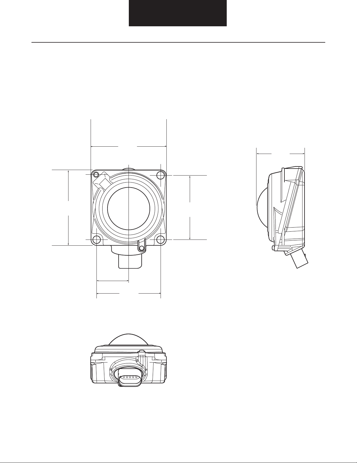
Forward Looking Radar Dimensions
3.85"
(98.0mm)
Space Claim
2.49"
(63.4mm)
3.87"
(98.5mm)
3.30"
(84.0mm)
1.60"
(40.6mm)
3.30"
(84.0mm)
6
Page 8

Side Object Detection Dimensions
Side Sensor
5.36"
(136.1mm)
Space Claim
0.82"
(20.8mm)
5.60"
(142.2mm)
3.53"
1.38"
(35.1mm)
0.9" (22.9mm)
2.04"
(51.8mm)
2.04"
(51.8mm)
3.24"
(82.3mm)
7
Page 9

Side Sensor Display
Space Claim
1.20" (30.5mm)
1.60" (40.6mm)
1.00"
(25.4mm)
2.10"
(53.3mm)
2.30"
(58.4mm)
39.00” ± 3.00"
(990.6mm ± 76.2mm)
2.00"
(50.8mm)
0.70" (17.8mm)
2.80"
(71.1mm)
2.00"
(50.8mm)
8
Page 10

Driver Interface Unit Dimensions
Space Claim
1.97"
(50mm)
4X R.207 (5.25)
.20” (5.2)
2X 1.56” (39.5)
1.58” (40.1)
1.61” (40.9)
3.67"
(93.18mm)
3.16” (80.2)
3.22” (81.8)
3.67” (93.18mm)
3.70"
(93.90mm)
2X 2.5˚
2X .63” (15.9)
2X 2.5˚
.22” (5.7)
4.07"
(103.39mm)
1.97” (50.0)
Panel Cut Out
(Without bezel)
9
Page 11
Mounting Requirements
Mounting Requirements
Overview
The installation of the Bendix™ VORAD® VS-400 System is intended to cover a wide range of commercial vehicle applications. This
publication is intended to be a reference for commercial vehicle installations using the vehicle’s SAE J1939 data link interface. For vehicles
without a SAE J1939 data link, some installation procedures may vary for a proper system installation and operation.
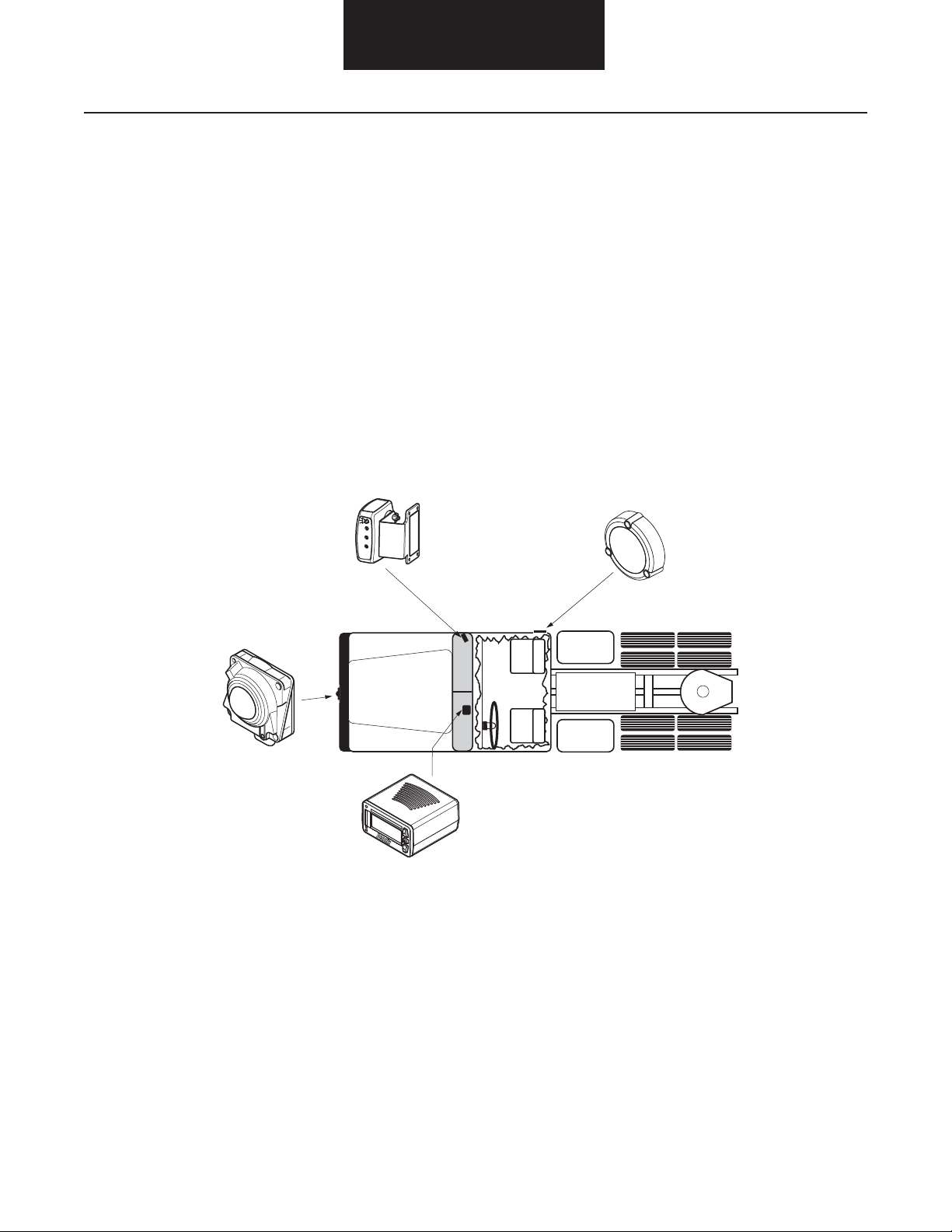
Typical Component Locations
Note: Not all components are required for every application.
Forward Looking
Radar (FLR)
Side Sensor
Display (SSD)
Driver Interface
Unit (DIU)
Side Sensor
(SS)
10
Page 12

Mounting Requirements
Mounting Requirements - Forward Looking Radar (FLR)
The Forward Looking Radar (FLR) determines the distance, lane position (azimuth), relative speed (velocity), and direction of vehicles
in front of the host vehicle. The FLR is a Doppler radar that transmits at a 77 GHz frequency. A built-in yaw rate sensor (gyro) provides
relative azimuth for lane positioning in turns. The SAE J1939 interface allows the FLR to be installed as a Bendix™ SmartCruise™ adaptive
cruise control only stand-alone unit, or as a component of the complete Bendix™ VORAD® VS-400 System.
The FLR can track multiple objects simultaneously in relative motion within the radar’s effective range of view. Relative motion is defi ned
as an object’s movement towards, or away from, the radar transceiver.
Note: The Forward Looking Radar is only activated while the vehicle is in motion.
Mounting Orientation
snoitacoL eloH gnitnuoMweiV tnorF
Mirror Must
11
Page 13
Mounting Requirements
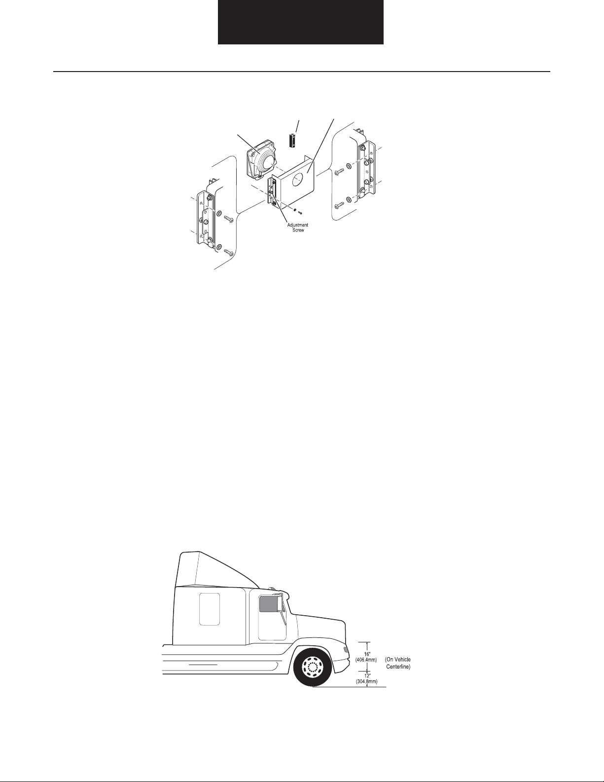
Installation
Bumper
(Optional)
Forward Looking
Radar
Note: The design of the Mounting Bracket may vary. This is a typical representation.
Located on the forward most position of the vehicle, the FLR transmits and receives low power, high frequency electromagnetic energy.
Transmitted energy that is refl ected off objects in front of the vehicle is received and processed by the radar’s internal microprocessor to
determine the object(s) relative distance, position (azimuth), speed (velocity), and direction of travel.
Mounting
Bracket
For proper operation, the 77GHz forward looking radar unit shall be installed on the vehicle with the following constraints:
• The radar unit must be rigidly attached to the forward most position of the vehicle chassis, perpendicular with the vehicle’s
forward thrust axis.
• The lateral position of the radar should be located as close to the vehicle’s center as possible (+/- 50mm).
• The vertical position of the radar must be at a minimum of 12” (304.8mm) and a maximum of 28” (711.2mm) from the ground.
• The radar must be installed in a manner that protects it from minor frontal impacts, as well as protecting the radar’s harness
connector from road debris.
• The mounting hardware must allow for a minimum of ±3° mechanical adjustment of the radar’s horizontal and vertical axis.
• The radar must be orientated so the harness connector is pointing in the downward position.
The mounting location must provide a clear view in front of the radar. Ideally, the radar will be recessed behind the profi le of the vehicle’s
front bumper or grill, but not to interfere with the radar’s sight profi le. See “No Radar Obstruction Zone” on next page.
12
Page 14
Mounting Requirements
Requirements
The Forward Looking Radar can be mounted on the front of the vehicle, or integrated behind a non-metallic body panel as long as the
mounting, alignment, and material requirements are met in the following sections.
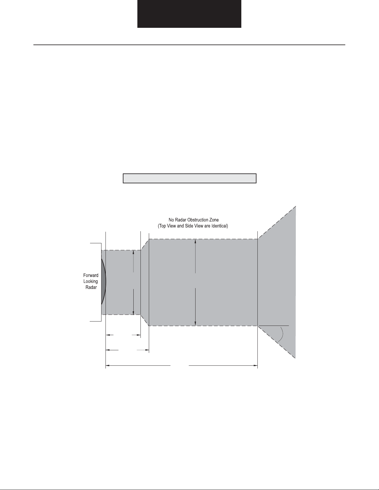
Field of View Defi nition
The Forward Looking Radar (FLR) fi eld of view in elevation and azimuth is illustrated below. The grey area represents a cross-cut view of
the three-dimensional “No Radar Obstruction Zone”.
Using the illustration below, the diameter of the hole in front of the Forward Looking Radar can de determined. For materials within 30mm
of the FLR, the hole diameter must be greater than 70mm. For materials 40mm from the front of the FLR, the hole diameter must be
greater than 90mm.
WARNING
!
▲
Any hole diameter less than the required size, will effect a clear line of sight for the FLR unit.
1.18"
(30mm)
1.57"
(40mm)
2.76"
(70mm)
4.72"
(120mm)
3.54"
(90mm)
0
45
13
Page 15
Mounting Requirements
Cover Material Requirements
Any material that may be located in the Forward Looking Radar’s fi eld of view (including bumpers, spoilers, etc.) can not be made out
of any metallic material or have any carbon content. It is recommended that any material that will be located in the FLR fi eld of view be
approved by Bendix Commercial Vehicle Systems prior to use.
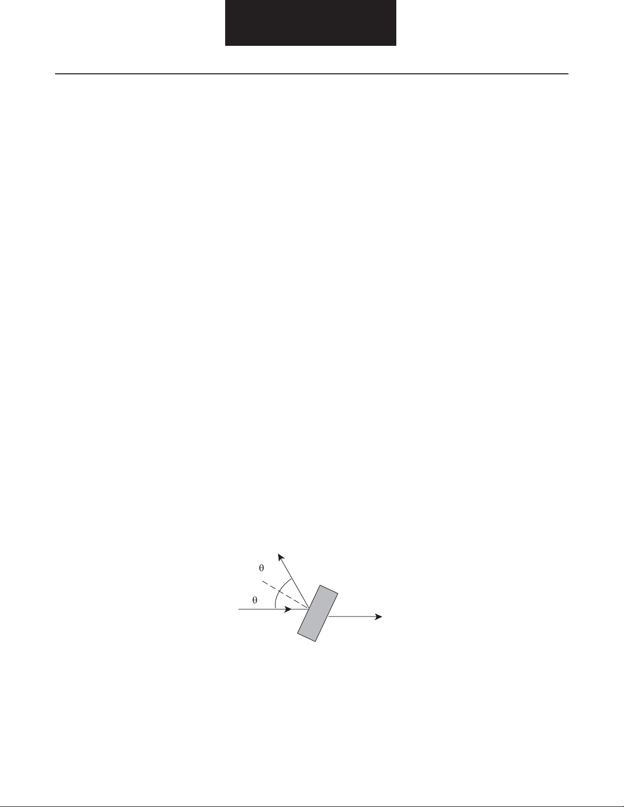
If the radar has a cover perpendicular to the radar beam, even a very slight vibration of the cover can cause the refl ected radar signal to be
seen as a very strong false target at close range. If the radar cover is not perpendicular by more than 5° then the returned refl ection does
not enter the receiver channel and hence is not detected. The recommended angle of the beam to the cover is 50° to 80°. There have
been applications that have the cover perpendicular, but the forward radar and the cover were directly mounted to each other to minimize
the cover’s movement to the radar module. This may be a diffi cult condition to maintain.
The cover must not contain any metal or high carbon concentrations, as this reduces the radar range. The electrical characteristics of
the cover material (on microwave RF) and its thickness can effect the range as well. Polymeric or ceramic material is recommended.
Recommended thickness are based on the cover’s angle. The table on the following page lists material thicknesses for a perpendicular or
80° angle cover. The ideal thickness also depends on the angle of incidence of the cover relative to the radar beam axis. The materials in
this table do not represent the only possible make up for a cover.
The recommendation scoring system has been applied as follows:
• Losses shall be less than 0.7dB.
• Thickness for rigidity reasons shall be greater than 2mm.
Thickness accuracy: +/- 0.15mm
Thickness recommendation is based on cover being a fl at unpainted surface that extends beyond the “No Radar Obstruction Zone” (see
previous page). Since paints can impact the losses, they need to be evaluated separately. As with the cover, the paint must not contain
metal or carbon.
• The thickness depends on the angle of incidence of the bumper shield located in the radar fi eld view relative to the radar beam
axis; it should be updated with the real angle.
• The angle of incidence is recommended to be between 50° to 80°; 90° is prohibited so as to avoid any spurious refl ection of the
radar beam back into the Forward Looking Radar.
Reflected
Beam
Radar
Beam
Radar
Beam
• Painting can induce extra losses that depend heavily on the painting thickness itself and on its painting process. These paints
need to be tested individually to assess their impact on the recommendations made in this document. For more information, see
the “Painting” section of this publication.
14
Page 16

Mounting Requirements
Options in white boxes are considered good options.
Options in grey boxes are considered possible options.
Material Recommended Recommended Material
Number Commercial Reference* Material Thickness (mm) Thickness with Cover @ 80° (mm)
1 Polyloy B69L62 PA6 2.25 2.22
TUC1228/93
2 CYCOLAC XMA 2.36 2.32
TUC1137/94 3.53 3.48
3 B70GFE30 2.1 2.07
TUC308/92
4 Hostacom PPX678/2 2.38 2.34
TUC1617/89
5 NORYL PX1112 2.35 2.31
TUC648/86 3.53 3.48
6 Hostaform C9021 2.33 2.29
TUC2559/83 3.5 3.45
7 Hostalen GDPE7255 2.56 2.52
TUC310/92 3.84 3.78
8 Hostacom PPR1042 2.51 2.47
TUC2641/86 3.77 3.71
9 PP-Kienb 2.39 2.35
3.58 3.53
10 ABS-Kienb 2.32 2.28
11 PPN 1080 2.58 2.54
3.88 3.82
12 XENOY 2.35 2.31
POCAN KU (PBT+PC)
13 ASA 2.26
14 PC - 0.1% soot 2.33 2.29
15 TICONA Celanex 2003 2.15 2.12
GV1/20 (PBT 20% GF)
16 TICONA Celanex 2003 2.05 2.02
GV1/30 (PBT 30% GF)
17 GE Plastics NORYL 2.4 2.36
PPX630
(PPE + PP 30% GF)
18 GE Plastics NORYL 2.1 2.07
GTX830
(PPE + PA 30% GF)
19 Ryton PPS R4-240 Nat 2.1 2.07
PPS 40% GF
*Commercial references are from European suppliers for the automotive market.
15
Page 17

Mounting Requirements
Vibration Specifi cations
Mounting mechanisms shall be designed to be compliant with the radar vibration spectrum illustrated below.
These vibration constraints are based on radio-frequency considerations in order to be compliant with the radar functional specifi cation.
There are no specifi c mechanical requirements along the Y- and Z-axis from a radio-frequency point of view. The mechanical movements
measured at the FLR center along the X-axis shall be less than the peak-to-peak displacement shown below.
Mechanical movement along the X axis shall be less than:
Note: All values are peak-to-peak.
• 5 Hz < 3 mm
• 10 Hz < 1 mm
• 20 Hz < 0.2 mm
• 30 Hz < 0.05 mm
• Above 40 Hz < 0.03 mm
The spectral density of the peak-to-peak displacement shown above should be measured over 50ms. Also, the spectral density of the
peak-to-peak displacement shall be less than the above-mentioned values divided by 3.
16
Page 18

Mounting Requirements
Painting
A wide variety of colors and textures can be applied to the Forward Looking Radar housing using commercially available organic paints
and conventional application processes.
Painting the component may assist with color degradation over time.
The following guidelines apply:
• Paints must not contain metal or carbon particles.
• Carbon content of paint could be a factor as high concentrations could reduce transparency.
• Paint thickness may impact the radar’s ability to pass through the surface.
• It is not recommended to paint the lens area.
• Do not paint the FLR mirror.
• Do not paint the mounting points as it could cause incorrect bracket engagement.
• Protect the connector breather element during any painting operation.
Front View
17
Page 19

Mounting Requirements
Alignment
WARNING
!
▲
The alignment of the Forward Looking Radar is critical to the correct operation of the Bendix™ VORAD® VS-400 system.
Improper alignment can cause the system to improperly detect objects in the vehicle’s path. Every precaution
should be taken to ensure the VS-400 alignment (both horizontal and vertical), is correct.
Alignment of the Forward Looking Radar is a repetitive process of adjusting the vertical and horizontal axis using the bracket screws.
Note: The vehicle must be parked on a level surface. If the vehicle is on an angled surface, then level compensations must be made to
ensure proper alignment.
Below are steps for a typical alignment procedure. Other companies, such as Hunter Engineering Company (11250 Hunter Drive,
Bridgeton, MO 63044, 314-731-3020), can also be contacted to establish alignment using professional alignment equipment.
Vertical Alignment
The steps for vertical alignment are as follows:
1. Hold a digital level against the fl at surface of the mounting bracket.
2. Use a 5/32" Allen wrench to loosen the locking screws.
Note: Failure to loosen both locking screws will result in damage to the alignment bracket.
3. Adjust the alignment screws until the digital level reads down 0° ± .2°.
4. Once aligned, tighten the locking screws.
Note: The illustration below shows a typical mounting and mounting bracket. The design may vary.
Locking
Screw
Alignment
Screws
18
Locking
Screw
Page 20

Mounting Requirements
Horizontal Alignment
The Forward Looking Radar must be facing straight ahead (azimuth) of the vehicle in order to optimally detect objects in the vehicle path.
1. Select two truck reference points that are identical and symmetrical about the truck centerline. Ensure the reference points are
equally aligned. Items such as fenders and headlights should not be damaged or distorted, otherwise, the alignment will be
inaccurate.
2. Center a 4'-6' (1-2m) straight edge across a fl at surface of the Forward Looking Radar bracket.
3. Measure the distance between the reference points and the face of the straight edge.
4. Use a 5/32" Allen wrench to loosen the locking screws.
Note: Failure to loosen both locking screws will result in damage to the alignment bracket.
5. Adjust the alignment screw until the two measurement points are equal within ± .1" (2.54mm).
6. Once the measurements are equal for both of the reference points, tighten the locking screws.
7. Check both the vertical and horizontal alignment:
a. Re-measure the reference points to ensure they are equal.
b. Use the digital level to verify the vertical alignment is still face down 0° from vertical ± .2°.
Note: The illustration below shows a typical mounting and mounting bracket. The design may vary.
Horizontal
Alignment Screw
Locking
Screw
19
Page 21

Mounting Requirements
Mounting Requirements - Side Object Detection (SOD)
Side Sensor
The Side Sensor should be mounted on the side of the vehicle, between 22" (558.8mm) and 36" (914.4mm) from the ground and at least
18" (457.2mm) rear of the side view mirror (see diagram below). Typically, the Side Sensor is located on the passenger side of the vehicle,
however, it can also be installed on the driver side of the vehicle.
Note: To reduce the possibility of the sensor detecting objects mounted to the vehicle like the steps or fuel tanks, make sure the face of the
sensor extends out a minimum of 5/16" (7.9mm) further than any other object within 6" (152.4mm) of the sensor's body.
WARNING
!
▲
Failure to mount Side Sensor properly will result in a solid red light indicating a constant detect mode.
This is critical to the correct operation of the VS-400 system.
20
22"
(558.8mm)
Page 22

Mounting Requirements
Sensor Orientation
The Side Sensor should be orientated so the embossed logo is parallel to the ground. Orientation is crucial for proper operation due to the
radar's polarized beam profi le.
Mounting the Sensor
The sensor should be mounted to the vehicle using 10-24 (6mm) stainless steel hardware. Bolts should be installed from the sensor side,
with fl at washers and nylock nuts on the backside. Torque hardware to a maximum of 22 lbs. in. (2.5 Nm). Do not over torque.
CAUTION
!
▲
Failure to observe torque setting will result in a damaged or cracked sensor and result in a void of warranty.
Side Sensor Display
The Side Sensor Display (SSD) should be mounted on the inside of the cab to the windshield pillar. The display unit should be positioned
in line with the side view mirror on the same side of the vehicle as the sensor without obstructing the driver's view.
WARNING
!
▲
The Side Sensor Display is not weather proof and must be mounted on the inside of the cab.
Failure to observe this warning will result in a void of warranty.
Side Sensor Display
To Side Sensor
Vehicles with dual left and right side sensors will have a display mounted on both the left and right windshield pillars.
21
Page 23

Mounting Requirements
Mounting Requirements - Driver Interface Unit (DIU)
The Driver Interface Unit (DIU) serves as the Bendix™ VORAD® Collision Warning System's central information center. The DIU provides
the driver with visual and audible alerts, as well as system confi guration, status, and diagnostic information. The DIU uses the vehicle's
SAE J1939 data link to communicate with the FLR, and other vehicle system devices.
Mounting Orientation
0.91"
1.65"
0.38"
(9.76mm)
Torque Specifi cation
(73.7mm)
3.67"
(93.18mm)
1.97"
(50mm)
3.67"
(93.18mm)
0.38"
(9.76mm)
Recommended mounting screws #6x19 Plastite thread forming screw, 3/8" (9.52mm) long. Torque mounting screw to 7 lbs. in. ±0.7
(0.79N•m ±0.08) maximum.
22
Page 24

Mounting Requirements
Installation
The DIU should be located where the driver can easily view and adjust the controls. This can be located on top of, or integrated into, the
dashboard fl ush with the front edge of the dashboard. Ease of operation and visibility of the DIU front panel are the primary considerations.
The method chosen for routing the wiring harness to the DIU should also be taken into consideration when determining the optimal
location.
Installation involves mounting the DIU to an in-dash or on-dash bracket. Attach the bottom of the DIU to the bracket with #6-19 Plastite
screws. The four mounting screw locations on the display are .393" (10mm) deep maximum. The screws should leave about .060" (1.5mm)
minimum of clearance between the tip and the bottom of the hole when installed. For example, a .375" (9.5mm) long screw with a .060"
(1.5mm) thick bracket would be acceptable.
Suggested Mounting Brackets
In Dash Installation: On Dash Installation:
Screws
23
Page 25

Electrical Requirements
Electrical Requirements - Forward Looking Radar (FLR)
Power Requirements
• Operating Voltage: +9-16Vdc
• Power Current: < 2 amps (average 1 amp)
• Recommended Fuse: 5 amp delayed fuse
Wiring Schematic
All electrical connections can be made in the engine compartment.
Front Looking Radar
J1
Mating Connector:
Connector Body:
J1
FLR 10-pin Connnector
Terminals:
Cable Seal:
Cavity Plug:
Terminal (20 AWG):
Terminal (18 AWG):
FEP
42122600
Amp / Tyco
0964972-1
0963531-1
0969005-2
0964274-2
FLR
10-pin Connector
J1
Link
3
4
5
9
10
T1
5 amp
T2
24
Page 26

Wiring Harness
Electrical Requirements
Notes:
All wires to be cross link TXL or equivalent unless otherwise specifi ed.
Use approved J1939 cable.
Interconnection Table
From To Code Gauge
J1-1 Plug – –
J1-2 Plug – –
J1-3 Plug – –
J1-4 J3-A Y ellow 20 AWG
J1-5 J3-B Green 20 A WG
J1-6 Plug – –
From To Code Gauge
J1-7 Plug – –
J1-8 Plug – –
J1-9 T1 Ground 18 AWG
J1-10 J2-A IGN1 18 AWG
J2-B T2 Ignition 18 AWG
25
Page 27

Ignition and Ground
Electrical Requirements
Pin # Description
J1-9 Chassis Ground
J1-10 +9-16VDC Switched
Ignition power (switched power)
run to main power lead that
feeds the ignition bus
26
Page 28

Electrical Requirements
J1939
Note: The J1939 data bus uses two (2) 120-ohm resistors to terminate each end of the data bus on the vehicle. These resistors must
remain in place for proper data bus communication. Due to the mounting location of the Forward Looking Radar, the closest of the
vehicle's J1939 terminators may have to be relocated nearer the radar as shown in the diagram below. Check the resistance of the
data bus using an ohmmeter before and after adding any device to the bus. With the ignition key in the OFF position, the resistance
of the data bus should read approximately 60-ohms (120 / 2).
Terminating
resistor
J-1939/11 data link
(OEM supplied)
_
+
GND
Shield
termination
5
4
3
Terminating
resistor
J1
Note: The illustration above shows J1939/11, however J1939/15 (2-wire) can be used.
Pin # Description
J1-3 J1939_SHIELD
J1-4 CAN_HI
J1-5 CAN_LO
27
Page 29

Electrical Requirements
Electrical Requirements - Side Object Detection (SOD)
The Side Object Detection (SOD) system consists of two components: a Side Sensor (SS) and a Side Sensor Display (SSD).
Power Requirements
• Operating Voltage: +9-32Vdc
• Power Current: Not to exceed 0.25 amps
• Recommended Fuse: 1 amp
Wiring Schematics
6
Side Sensor
P2 SOD
1
5
2
3
4
Connector Rear
4
1
3
2
Connector Rear
ODU P1
Notes:
All wires to be cross link GXL or equivalent unless otherwise specifi ed.
Use approved J1939 cable.
Interconnection Table
From To Code Gauge
J2-1 T2 Ignition 18 AWG
J2-2 T3 Chassis Ground 18 AWG
J2-3 J1-3 Communication 18 AWG
J2-4 J1-1 Power 18 AWG
** For this example, the right turn signal is used, however, the left turn signal could also be used for a Side Sensor installed on the driver
side of the vehicle.
From To Code Gauge
J2-5 J1-2 Signal Ground 18 AWG
J2-6 No Connection – 18 AWG
J1-4 T1 Right Turn Signal* 18 AWG
28
Page 30

Ignition and Ground
Electrical Requirements
P2 SOD
fuse
Ignition power (switched power)
run to main power lead that
feeds the ignition bus
fuse
Ignition power
(switched power)
run to main power lead
that feeds the ignition bus
6
1
5
2
3
4
29
Page 31

Electrical Requirements
Electrical Requirements - Driver Interface Unit (DIU)
Power Requirements
• Operating Voltage: +9-32Vdc
• Power Current: Not to exceed 2 amps
• Recommended Fuse: 4 amp
Wiring Schematics
Driver Interface Unit
DIU 8-pin Connnector
J1
Mating Connector:
Connector Body:
Terminal:
Terminal (18/20 AWG):
Molex
30700-1081
Amp / Tyco
1393366-1
DIU
8-pin Connector
1
2
3
J3
T3
J1939 Data
6
7
30
Page 32

Wiring Harness
Electrical Requirements
T3
T4
T5
J3
J1
J1
Mating Connector:
Connector Body:
Terminal:
Terminal (18/20 AWG):
J2
Mating Connector:
Connector Body:
Cover:
Terminal:
4 Amp Fuse:
J3
Mating Connector:
Connector Body:
Wedge:
Socket:
Molex
30700-1081
Amp / Tyco
1393366-1
Packard
12092449
12033731
12020156
12004004
Deutsch
DTM06-2S
WM-2S
0462-201-20141
Quantity
1
4
4
1
1
2
1
1
1
2
Notes:
All wires to be cross link GXL or equivalent unless otherwise specifi ed.
Use approved J1939 cable.
Interconnection Table
From To Code Gauge
J1-7 J3-A Y ellow 20 AWG
J1-6 J3-B Green 20 A WG
J1-5 T1 Ground 18 AWG
J1-4 J2-A IGN1 18 AWG
T1
T2
J2
From To Code Gauge
J2-B T2 Ignition 18 AWG
J1-1 T3 R-SPK 20 AWG
J1-2 T4 L-SPK 20 AWG
J1-3 T5 Blackout 20 AWG
31
Page 33

Ignition and Ground
8-pin Connector
Electrical Requirements
Driver Interface Unit
DIU
Pin # Description
J1-4 +9-32VDC Switched
J1-5 Chassis Ground
FRONT VIEW
DIU (8-pin Connnector)
1
3
2
4
5
78
6
32
Page 34

J1939
Electrical Requirements
Terminating
resistor
J-1939/15 data link
(OEM supplied)
4
857
2
3
1
6
Note: The illustration above shows J1939/11, however J1939/15 (2-wire) can be used.
Pin # Description
J1-6 J1939 J1-7 J1939+
Terminating
resistor
33
Page 35

Optional I/O
Electrical Requirements
Driver Interface Unit
DIU
8-pin Connector
FRONT VIEW
DIU (8-pin Connnector)
WIRE SOFTWARE
PIN # DESCRIPTION FUNCTION INPUT / OUTPUT REQUIRED
1 R-SPK Right Speaker Output - 4 ohm 1 watt Yes
2 L-SPK Left Speaker Output - 4 ohm 1 watt Yes
3 Blackout Blackout_Input Input - Tri-state Yes
34
Page 36

Final Test
Final Test
Bendix™ VORAD® VS-400 SmartCruise® Adaptive Cruise OEM:
Control and Collision Warning Chassis S/N:
Trans Model: Trans S/N:
Functionality T esting Clutch Size/Type:
Shift Control S/N:
Description Yes No Corrected
Validate SmartCruise® Adaptive Cruise Control Operation and CWS Operation (dyno environment preferred).
1. Start truck and verify VS-400 system powers-up (goes through bulb check with no faults
indicated).
2. Bring truck up to road speed (50-60 MPH suggested).
3. Activate cruise control using vehicle controls (set speed switch, lever, button, etc.).
Visually inspect DIU for SmartCruise activation notifi cation.
Let truck speed stabilize.
4. Step on brake. (Truck should deactivate cruise function and coast).
Reactivate cruise function. (Truck should accelerate to set speed).
5. Step on clutch. (Truck should defuel, coast). Reactivate cruise function.
6. Step on accelerator. (Truck should accelerate).
Dyno Environment
7. Resume speed
Lower the door to the dyno, or move a refl ective target in front of Forward Looking Radar.
(15-30 feet away from and directly in front of Forward Looking Radar).
While the target is moving in front of radar, the VS-400 should see the target, (indicated
by the DIU displaying lights, CWS alerts, LCD screen, and audibles), and the vehicle
should defuel and apply the Jake brakes to slow vehicle speed.
8. Assuming the above functions performed properly, the vehicle defueled, the target
stopped moving (indicated by no target detection in the DIU), the vehicle engine did not
drop below 1000 rpm, and the road speed did not drop below minimum requirements, the
vehicle should now accelerate back to the set speed on its own.
9. If all tests performed and operated as outlined, the Adaptive Cruise Control and CWS
functionality test has completed properly, and the Adaptive Cruise Control validation
process is complete.
Note: Because of the high horsepower engines in use today, and the ability of the Jake
brakes to apply twice the braking horsepower to the rear wheels, the truck may
defuel to the point the vehicle drops out of Cruise before the target has stopped
moving. This moving target, (indicated by the DIU displaying lights, LCD screen,
and audibles) would indicate a viable reason to defuel; thereby causing the vehicle
to Jake to the point the engine will disengage the cruise function. This is normal
and not a defi ciency with the system.
Note: To test each specifi c CWS alert requires accurate road speed and target closing
distance calculations. Therefore, additional procedures are necessary to facilitate
this functionality.
35
Page 37

Appendix
Retrofi t Information
Retrofi t Recommended Practices
Body builder electrical systems that are to be interconnected with the VS-400 electrical system should adhere to the latest
recommendations of SAE J1292. In addition to SAE J1292, the following recommendations should be followed:
1. All wiring terminals should be properly insulated to prevent "short circuits". All terminals should be of insulation grip design to
provide a reliable connection and to prevent terminal fatigue.
2. Terminals and splices that are connected outside the body should be moisture resistant design. Molded insulator for ring
terminals should be used. Molded connector/insulators are recommended for use with blade or pin type terminals.
3. Wires must be routed to provide at least 3" (75mm) clearance to moving parts, unless positively fastened or protected by conduit.
4. Wire routing should avoid areas where temperatures exceed 80°C [180°F] and a minimum clearance of 6" (150mm) should be
maintained from exhaust system components. Where compliance with this requirement is not possible, heat insulation and heat
shields are required.
5. Wire routing and component mounting (switches, relays, etc.) should be located to be easily removed for service. Do not
surround the components with body structure that will prevent removal for service.
6. Wiring to all circuit components (switches, relays, etc.) in exposed locations shall provide a drip loop to prevent moisture from
being conducted into the device via the wire connection.
7. Routing wiring into wheel splash areas should be avoided. When such routing cannot be avoided, adequate clipping or protective
shielding is required to protect wiring from stone and ice damage.
8. Routing wires under the frame side-members or at points lower than the bottom frame fl ange should be avoided to prevent
damage to the wires in off-road operations.
9. The wire retainers and grommets installed by the assembly plant are designed to accommodate only the OEM installed wires.
Additional wiring or tubing must be retained by additional clips. When added wires to tubes are routed through sheet metal
panels, new holes must be used (with adequate wire protection and sealing).
10. All wiring connections to components of the factory-installed system must be accomplished by using the correct mating wire
termination. Connections on studs and ground connections must use ring type terminations.
11. When it is necessary to splice wires, the splice must be adequately crimped to provide a good mechanical and electrical
connection. Double wall heat shrink tubing should be used where the outer wall will provide adequate electrical insulation and the
inner wall melts and seals the splice from the envionrment.
12. Never add another circuit or splice into the ignition or battery power supplies. The fuses and curcuit breakers installed
at the assembly plant are designed to protect the wiring and electrical components from overloads. Never remove a factory
installed fuse or circuit breaker and replace with a high value device. If the added electrical device causes "fuse blow", or circuit
breaker cycling, it indicates the total load is too high for the factory-installed circuit protection and requires revisions in the added
circuit; not an increase in fuse or circuit breaker size. In this case, the device cannot be added directly to the circuit, but must be
connected through a separate hang-on switch or relay of the correct capacity, using added wiring of the correct gauge. Failure
to adopt this precaution will lead to switch contacts burning. The following wire table suggests wire gauges for various maximum
current draws and will aid in the selection of the correct wire size. The current capacity of a given wire varies with temperature
and type of insulation, but the following values are generally acceptable. If the total electrical load on the circuit, after the addition
of electrical equipment, is less than the fuse protection in that circuit or less than the capacity of some limiting component
(switch, relay, etc.), the items to be added can be connected directly to that circuit. The connection points and allowable loads
are normally found in the owner's manual. Contact the OEM with any questions.
36
Page 38

Appendix
Maximum Current Capacity
Wire Gauge (Crosslink Polythlene Copper Wire)
20 14 Amps
18 18 Amps
16 24 Amps
14 34 Amps
12 42 Amps
10 58 Amps
8 80 Amps
6 110 Amps
37
Page 39

J1939/11 Data Link Detail
Appendix
Recommended
Cable
Manufacturer
Champlain
Champlain
Raychem
Raychem
Raychem
BICC Brand-Rex
Shield Termination
J1939 (+)
J1939 (-)
J1939 Shield
Ref. Body Signal Terminals (QTY) Shield Terminal (QTY)
A
DT06-3S-P032
B
DT06-3S-P032
C
DT04-3P-P007
D
DT04-3P-P006
E
DT04-3P-E008
F
DT04-3P-LE08
** If an additional wire is added to the drain for insertion into the connector,
no shield terminal is used and the signal terminal quantity is 3.
If the drain wire is to be directly inserted into the connector,
then a shield terminal is used and the signal terminal quantity is 2.
0462-201-1631 (3) **
0462-201-1631 (3) **
N/A
N/A
0460-202-1631 (3) **
0460-202-1631 (3) **
Cable
Part
Number
23-00013-001
23-00028-001
2021D0311
2021D0001
2021D0301
T-14945
0462-221-1631 (1) **
0462-221-1631 (1) **
N/A
N/A
0460-247-1631 (1) **
0460-247-1631 (1) **
Round
Yes
No
No
No
Yes
Yes
J1939 (+)
(PIN "A")
Color
Yellow
Yellow
Yellow
Yellow
Yellow
Yellow
Wedge
W3S-1939-P012
W3S-P012
N/A
N/A
W3P
W3P-1939
A/NA/NA/N600P-S3-60TDG
J1939 (-)
(PIN "B")
Color
Green
Green
Green
Green
Green
Green
Function
Through Connector
Stub Connector
"T" Receptacle
120 Ohm Termination
ECU Receptacle
Flang Receptacle
120 Ohm Termination
J1939
(PIN "C")
Shield
N/A
N/A
N/A
N/A
N/A
N/A
38
ECM #1
VS-400
FLR
VS-400
DIU
F
E
1.00 Meter
Max Length
B
G
B
C
A
AA
F
Shield
C
B
B
AA
CD
1.00 Meter
Max Length
B
A
A
Termination
16 Gage GXL
40.00 Meter
Max Length
Page 40

Appendix
SAE J1939/11 Recommended Cable Termination Procedure
1. Remove cable outer jacket approximately 1" (25mm).
2. Remove foil from exposed wires to within 1/16" (2mm) from cable jacket.
3. Strip insulation from data wires .25" (7mm).
4. Attach extended wire barrel socket contact to the drain wire or attach adhesive fi ller solder sleeve and wire to drain wire per
manufacturer's recommendations. For the solder sleeve option, cut the wire on the solder sleeve to a length of 1" (25mm) and
strip the insulation back .25" (7mm).
5. Crimp the appropriate terminal on each data wire and solder sleeve wire or the extended socket per the manufacturer's
recommendations.
6. Slide the adhesive fi ller shrink tube over the cable end.
7. Install the terminals into the connector body per the manufacturer's instructions.
8. Install the wedge in the front of the connector body per the manufacturer's instructions.
9. Apply the shrink tube to the end of the connector body per the manufacturer's instructions.
Cable
Extended Socket
Drain Wire
Shrink Tube
Solder Sleeve
with Wire
Data Wires
OR
Plug
Wedge
Terminals
Final Assembly
39
Page 41

Appendix
SAE J1939/11 Recommended Cable Splice Procedure
1. Remove cable outer jacket approximately 1-1/2" to 4" (40 to 100mm).
2. Remove foil shield from exposed wires to within 1/16" (2mm) from cable jacket.
3. Strip insulation from data wires .25" (7mm).
4. Attach X-link wire to drain wire with crimp slice per manufacturer's recommendation.
5. Slide adhesive fi lled shrink tube over crimp splice.
6. Slide adhesive fi lled shrink tube over cable end.
Crimp
Shrink Tube
Cross Link
Drain Wire
Shrink Tube
Cable
Data Wires
Drain Wire
Data Wires
Shrink Tube
Final Assembly
Existing Drain Wire Splice/Sealing Method
1. Remove cable outer jacket approximately 1-1/2" to 4" (40 to 100mm).
2. Remove foil shield from exposed wires to within 1/16" (2mm) from cable jacket.
3. Strip insulation from data wires .25" (7mm).
4. Crimp stub branch lines and drain wire to main backbone data lines and drain wire.
5. Cover each splice with insulation shrink tubing.
6. Wrap unshielded area with shielding material.
7. Apply adhesive fi lled shrink tube to splice junction.
8. For shield termination, crimp maximum 16 gauge GXL wire to drain wire.
Cable
40
Page 42

J1939/15 (lite) Data Link Detail
Maximum 131 feet (40 meters) length.
Maximum 10 feet (3 meters) stub length.
Maximum 10 modules on segment.
Twisted pair (18 or 20 AWG) with 1 twist per inch.
120 Ohm terminating resistors must be used.
Connector at ECU is not defi ned.
The third pin for sheild is not used in 'in-line' the T-connectors.
Appendix
Recommended
Cable
Manufacturer
Champlain J1939/15 Yes Yellow Green
Twisted Pair
J1939 (-)
J1939 (+)
Ref. Body Signal Terminals (QTY) Wedge
A
B
C
D
E
F
G
J1939 (+)
J1939 (-)
Cable
Part
Number
ECM #1
ECM
Round
Function
J1939 (+)
(PIN "A")
Color
VS-400
MODULES
J1939 (-)
(PIN "B")
Color
E
1.00 Meter
Max Length
B
G
B
E
B
B
B
3.00 Meter
Max Length
A
AA
A
C
F
C
40.00 Meter
Max Length
AA
CD
A
41
Page 43

Appendix
Wiring Schematics
Bendix™ SmartCruise® Adaptive Cruise Control and/or Collision Warning System
Using the OEM Integrated Dash as Display
42
Page 44

™
Bendix
Using the Driver Interface Unit as Display
SmartCruise® Adaptive Cruise Control and/or Collision Warning System
Appendix
43
Page 45

Appendix
Collision Warning System with Side Object Detection
44
Terminating
Resistor
Page 46

Appendix
Connector Pin Descriptions
Forward Looking Radar
10-pin TRW Connector
PIN # SIGNAL NAME TYPE INTERFACE LEVEL
1 NO_CONNECTION – –
2 NO_CONNECTION – –
3 J1939_SHIELD TRUCK J1939 LINK
4 CAN_HI – TRUCK J1939 LINK
5 CAN_LO – TRUCK J1939 LINK
6 NO_CONNECTION – –
7 NO_CONNECTION – –
8 NO_CONNECTION – –
9 GROUND POWER CHASSIS GROUND
10 IGNITION POWER +12V SWITCHED
Driver Interface Unit
8-Pin Molex Connector
PIN # SIGNAL NAME TYPE INTERFACE LEVEL
1 RIGHT_SPEAKER O SPEAKER DRIVER 4 OHM / 1 WATT
2 LEFT_SPEAKER O SPEAKER DRIVER 4 OHM / 1 WATT
3 BLACKOUT_INPUT / SPARE I TRI-STATE INPUT
4 BATTERY POWER +9-32VDC SWITCHED
5 GROUND POWER CHASSIS GROUND
6 CAN_LO TRUCK J1939 LINK
7 CAN_HI TRUCK J1939 LINK
8 SPARE_ANALOG I TRI-STATE INPUT
45
Page 47

Appendix
Side Sensor Display Unit
4-pin Deutsch Connector
PIN # SIGNAL NAME TYPE INTERFACE LEVEL
1 POWER I +12V FROM SENSOR
2 GROUND POWER CHASSIS GROUND
3 COMMUNICATION I
4 TURN_SIGNAL I +12V
Side Sensor
6-pin Deutsch Connector
PIN # SIGNAL NAME TYPE INTERFACE LEVEL
1 IGNITION POWER +12V SWITCHED
2 GROUND POWER CHASSIS GROUND
3 COMMUNICATION O
4 POWER O +12V
5 SODDU-GROUND POWER GROUND
6 NO CONNECTION – –
46
Page 48

Vendor Contact Information
Appendix
AMP/Tyco
Harrisburg, PA
Tel: 800.522.6752
http://www.tycoelectronics.com/
Champlain Cable Corporation
175 Hercules Drive
Colchester, Vermont 05446
Tel: 800.451.5162
http://www.champcable.com/
Deutsch
LADD Industries
4849 Hempstead Station Dr.
Kettering, OH 45429
Tel: 800.223.1236
http://www.laddinc.com
FEP
FAHRZEUGELEKTRIK PIRNA GmbH & CO. KG
Hugo-Küttner-Straße 8
01796 Pirna
Tel: +49 3501 514 0
http://www.fepz.de/en/e_index.html
Littelfuse World Headquarters
800 E. Northwest Highway
Des Plains, IL 60016
Tel: 847.824.1188
Fax: 847.391.0894
http://www.littelfuse.com
Molex
2222 Wellington Court
Lisle, IL 60532-1682
Tel: 800.78MOLEX
http://www.molex.com
Packard
Delphi Connection Systems
5725 Delphi Drive
Mail Station 483.400.301
Troy, MI 48098
Tel: 800.610.4835
http://www.delphisecure2.com/site/home/homemain.asp
Packard Distributor
Power & Signal Group
World Headquarters
4670 Richmond Road
Suite 120
Cleveland, OH 44128
Tel: 800.722.5273 or 216.378.6600
http://www.powerandsignal.com
47
Page 49

901 Cleveland Street • Elyria, OH 44035 • 1-800-AIR-BRAKE • www.bendix.com
BW2772 ©2010 Bendix Commercial Vehicle Systems LLC, a member of the Knorr-Bremse Group • All Rights Reserved • 09/10
The Roadranger® System features
®
brand foundation brakes.
Bendix
 Loading...