

Page 1
Installation
Instructions
Patents Pending
BENDIX® TRDU™ TRAILER REMOTE
DIAGNOSTIC UNIT
The Bendix® TRDU™ (Trailer Remote Diagnostic Unit) is a diagnostic
tool providing the technician with a visual indication of component
Diagnostic Trouble Code (DTC) information from Bendix® Antilock
Brake Systems (ABS) for trailers. The TRDU™ unit communicates
across PLC4Trucks supporting common diagnostic messages.
Additionally, the Bendix® TRDU™ provides odometer mileage readout,
a method for clearing the ABS component Diagnostic Trouble Codes,
and allows the user to self-congure the ABS ECU conguration on
Bendix® TABS-6, and MC-30™ with PLC ECUs. It will also clear most
A-18™ ABS with PLC ECUs (in this case, certain sensor DTCs require
the vehicle to be driven).
The TRDU™ unit is specically designed for use with Bendix® ABS and
although Bendix has included some competitive support, based on
reading some standard diagnostic messages, Bendix makes no claims
for its operation and/or usability with other brands of ABS systems.
DEVICE FEATURES
The TRDU™ unit attaches to the main trailer electrical connector
(SAE J560) located at the nose of the trailer by using a 7 to 7 pin
adapter (802165).
The TRDU™ tool allows the technician to:
• Troubleshoot ABS system component problems using Diagnostic
Trouble Code reporting via LEDs. Blink codes are also activated
when the TRDU™ unit is rst attached to trailers with a TABS-6
ECU (the full readout is displayed using the trailer-mounted ABS
lamp).
• Reset the Diagnostic Trouble Codes on Bendix® ABS ECUs by
holding a magnet over the “B” of the Bendix logo on the face of
the TRDU™ tool for 6, or less, seconds.
• Enter the Self-Conguration Mode for MC-30 and TABS-6 standard
& premium models by holding a magnet over the reset area for
greater than 6 seconds but less than 11 seconds. Note that, in
the case of TABS-6 advanced ECUs, to enter the self-conguring
mode a connected PC with Bendix® ACom® Diagnostics Software
is required.
• Read the odometer data. This information is continuously ashed
out using the TRDU™ unit’s ODO LED as soon as communications
is established, and repeats every 10 seconds.
OPERATION
When the TRDU™ unit is plugged in and receiving power (through
the adapter), all the LEDs will illuminate for one half-second, and the
green LED VLT will ash 4 times to indicate communications have
been established. The blue ODO LED will immediately begin blinking
out the odometer reading from the trailer ABS ECU, and continue
blinking odometer reading out every 10 seconds.
• If the ABS ECU has no active Diagnostic Trouble Code(s), only
the green LED will remain illuminated.
• If the ABS ECU has at least one active Diagnostic Trouble Code
the TRDU™ tool displays the rst Diagnostic Trouble Code by
illuminating the red LEDs, indicating the malfunctioning ABS
component and its location on the vehicle.
• If there are multiple Diagnostic Trouble Codes on the ABS system,
the TRDU™ unit will display one Diagnostic Trouble Code at a time,
then after the rst Diagnostic Trouble Code has been repaired and
cleared, the next code will be displayed.
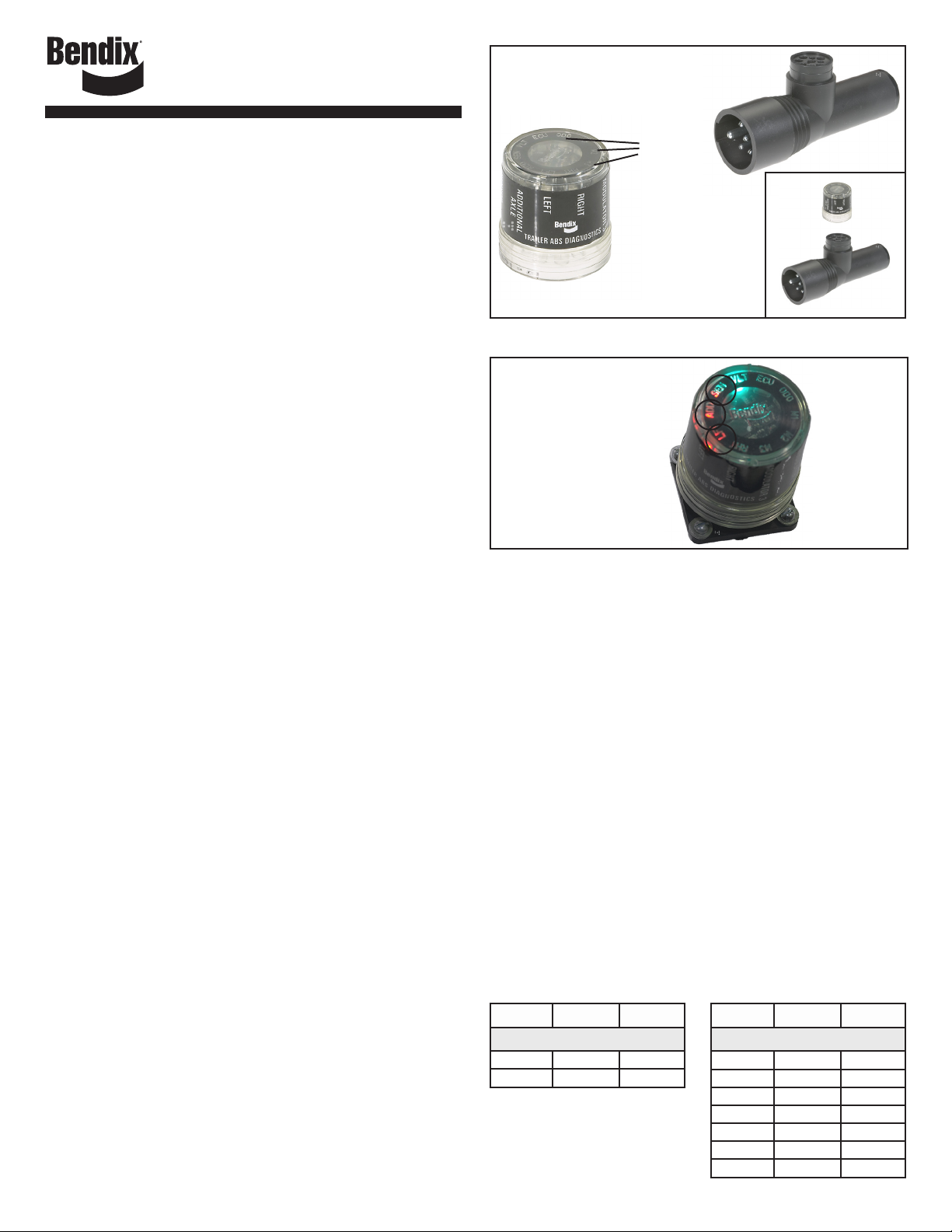
LED lights
illuminate
Diagnostic
Trouble
Codes
(10 locations
in total)
FIGURE 1 - THE BENDIX® TRAILER REMOTE DIAGNOSTIC
UNIT AND ADAPTER
For example, if
the Diagnostic
Trouble Code is Left
Additional Sensor,
the TRDU will display
the Diagnostic Trouble
Code as shown.
FIGURE 2 - EXAMPLE OF A DIAGNOSTIC TROUBLE CODE
Left
Additional
Sensor
DTC
TYPICAL LED ALERTS ARE:
Right sensor (RHT + SEN), Left sensor (LFT + SEN), Right additional
sensor (RHT + ADD + SEN), Left additional sensor (LFT + ADD +
SEN), Modulator 1 (M1), Modulator 2 (M2), Modulator 3 (M3), ECU,
VLT (Flashing indicates either over or under voltage condition), All
LEDs in a circular pattern = no communication.
To pinpoint the root cause and to ensure the system Diagnostic Trouble
Code is properly corrected the rst time, additional troubleshooting
may be necessary.
For more information on troubleshooting and repairing Bendix ABS
Diagnostic Trouble Codes, download the ABS service data sheet from
www.bendix.com, or order paper copies from the Literature Center
at bendix.com.
ABS Controller Service Data Sheet
A-18™ Controller . . . . . . SD13-4757 (order BW2262)
MC-30™ Controller . . . . . SD13-4834 (order BW2189)
TABS-6™ Stnd. & Prem. Controller SD13-4767 (order BW2469)
TABS-6™ Adv. Single Channel . . SD13-47671 (order BW2718)
TABS-6™ Adv. Multi Channel . . SD13-47672 (order BW2726)
For other ABS manufacturer’s ECUs, obtain the appropriate service
information from the ABS manufacturer. In some cases, the following
chart may assist the technician when troubleshooting certain systems:
TRDU Wabco* Haldex**
2S/1M Systems
SEN YE1 S1A
ADD YE2 S1B
* Trademark of WABCO
** Trademark of HALDEX AB
TRDU Wabco* Haldex**
4S Systems
SEN YE1 S3A
ADD YE2 S3B
LFT BU1 S2A
RHT BU2 S2B
M1 Red Red
M2 Yellow Yellow
M3 Blue Blue
1
Page 2

Note: If connected to a Bendix product, the TRDU will show the sensor
location (e.g. SEN & LFT Led’s).
If connected to other OEM systems, only one LED will illuminate for
a sensor fault, and the corresponding OEM designation must be read
from the label on the side of the TRDU. Consult OEM documentation
for wheel end location. Mod faults are interpreted by color, on the label.
RESET FUNCTION
The magnetic reset switch is located at the “B” in the Bendix logo
in the top of the TRDU™ unit. Activation requires a magnet with 30
gauss minimum.
Using a magnet, the reset operations are:
1. If the magnet is held over the reset switch for less than 6 seconds
and then removed, all Diagnostic Trouble Codes are cleared.
2. If the magnet is held over the switch for more than 6 seconds
but less than 11 seconds the self-conguration command is sent
(Bendix MC-30™ and TABS-6 ECUs only). The self-conguration
is indicated when the LEDs illuminate then ash on and off in 2
half-circle patterns.
NOTE: The “clear codes” and “self conguration” functions may not
operate with other ABS manufacturer’s ECUs.
AFTER REPAIRS ARE MADE
It is recommended at the end of any repair to switch off and restore
the power to the ABS ECU, then check the ABS Warning Lamp and
TRDU™ tool to see if any Diagnostic Trouble Codes remain.
ODOMETER FUNCTION
The odometer mileage will be blinked out on the blue LED labeled
ODO immediately upon the ABS ECU establishing communications
and repeated every 10 seconds. The odometer reading is displayed
by the thousands (x 1000). e.g. 152,287 miles would be presented as:
152 (x1000) or 1 blink – pause, 5 blinks – pause, and 2 blinks.
A zero will be displayed by quickly strobing the Blue ODO LED twice.
ABS WARNING LAMP BLINK CODES
NOTE: This feature only available with TABS-6™ ECUs.
When communications with a trailer TABS-6™ ECU is established, the
TRDU™ will cause the TABS-6™ ECU to blink out any active codes
on the trailer warning lamp.
Blink Code Lamp Timing
Action Timing
Duration of indicator blink pulse (lamp on) 0.4 seconds
Duration of indicator blink pulse (lamp off) 0.4 seconds
Strobe characteristics for display of zero
digit (ON-OFF-ON)
Duration between blink code digits 1.0 seconds
Duration between blink code messages 2.5 seconds
Du rat i on of in dic ato r illu min ati o n at
completion of messages
0.2 Hz for 0.4 seconds @
50% duty cycle
5.0 seconds
ECU COMMUNICATION PROBLEMS
If the TRDU™ unit does not establish communication with the
ABS ECU, it will illuminate each LED in a clockwise pattern.
This pattern will continue until the ABS ECU responds and
communication has been established. Note: The TRDU™
cannot communicate with non-PLC ABS units.
Possible sources of communication problems are:
1. The J2497 (PLC4Truck) communication is not present at the SAE
J560 connector, or the ECU does not support PLC diagnostics.
S-1439 © 2010 Bendix Commercial Vehicle Systems LLC 8/2010 Printed in U.S.A. All Rights Reserved.
2. The ECU does not support PID194, a standard message dened
in the J1587 specication.
3. The ECU, J560, or diagnostic connector has no power.
4. The TRDU™ unit can not arbitrate bus access.
5. A malfunctioning TRDU unit.
If no active codes are present, the warning lamp will display 1-1
repeatedly for TABS-6 equipped trailers.
This will provide the user more detailed information regarding the
code and it will be a reminder to remove the TRDU™ after service is
complete.
If communications issues continue, contact Bendix at 1-800-AIR-BRAKE
(1-800-247-2725) Monday through Friday 8 a.m. to 6 p.m. EST. Please
have the Bendix ECU type, product part number & conguration,
vehicle make and model information when you call.
WARNING! PLEASE READ AND FOLLOW THESE
INSTRUCTIONS TO AVOID PERSONAL INJURY
OR DEATH:
When working on or around a vehicle, the following
general precautions should be observed at all times.
1. Park the vehicle on a level surface, apply the parking brakes,
and always block the wheels. Always wear safety glasses.
2. Stop the engine and remove ignition key when working
under or around the vehicle. When working in the engine
compartment, the engine should be shut off and the ignition
key should be removed. Where circumstances require that
the engine be in operation, EXTREME CAUTION should be
used to prevent personal injury resulting from contact with
moving, rotating, leaking, heated or electrically charged
components.
3. Do not attempt to install, remove, disassemble or assemble
a component until you have read and thoroughly understand
the recommended procedures. Use only the proper tools
and observe all precautions pertaining to use of those tools.
4. If the work is being performed on the vehicle’s air brake
system, or any auxiliary pressurized air systems, make
certain to drain the air pressure from all reservoirs before
beginning ANY work on the vehicle. If the vehicle is equipped
with an Bendix® AD-IS® air dryer system or a dryer reservoir
module, be sure to drain the purge reservoir.
5. Following the vehic le manuf acturer’s recommen ded
procedures, deactivate the electrical system in a manner
that safely removes all electrical power from the vehicle.
6. Never exceed manufacturer’s recommended pressures.
7. Never connect or disconnect a hose or line containing
pressure; it may whip. Never remove a component or
plug unless you are certain all system pressure has been
depleted.
8. Use only genuine Be ndix® brand replacemen t parts,
components and kits. Replacement hardware, tubing, hose,
ttings, etc. must be of equivalent size, type and strength
as original equipment and be designed specically for such
applications and systems.
9. Components with stripped threads or damaged parts should
be replaced rather than repaired. Do not attempt repairs
requiring machining or welding unless specically stated
and approved by the vehicle and component manufacturer.
10. Prior to returning the vehicle to service, make certain all
components and systems are restored to their proper
operating condition.
11. For vehicles with Automatic Traction Control (ATC), the ATC
function must be disabled (ATC indication lamp should be
ON) prior to performing any vehicle maintenance where one
or more wheels on a drive axle are lifted off the ground and
moving.
Any references in these instructions to WABCO, HALDEX and any other company or
trademark are solely for identication and/or cross reference purposes. The trademarks
are the property of their respective companies and are not afliated with, or endorsing
Bendix CVS LLC.
2
 Loading...