

Page 1
®
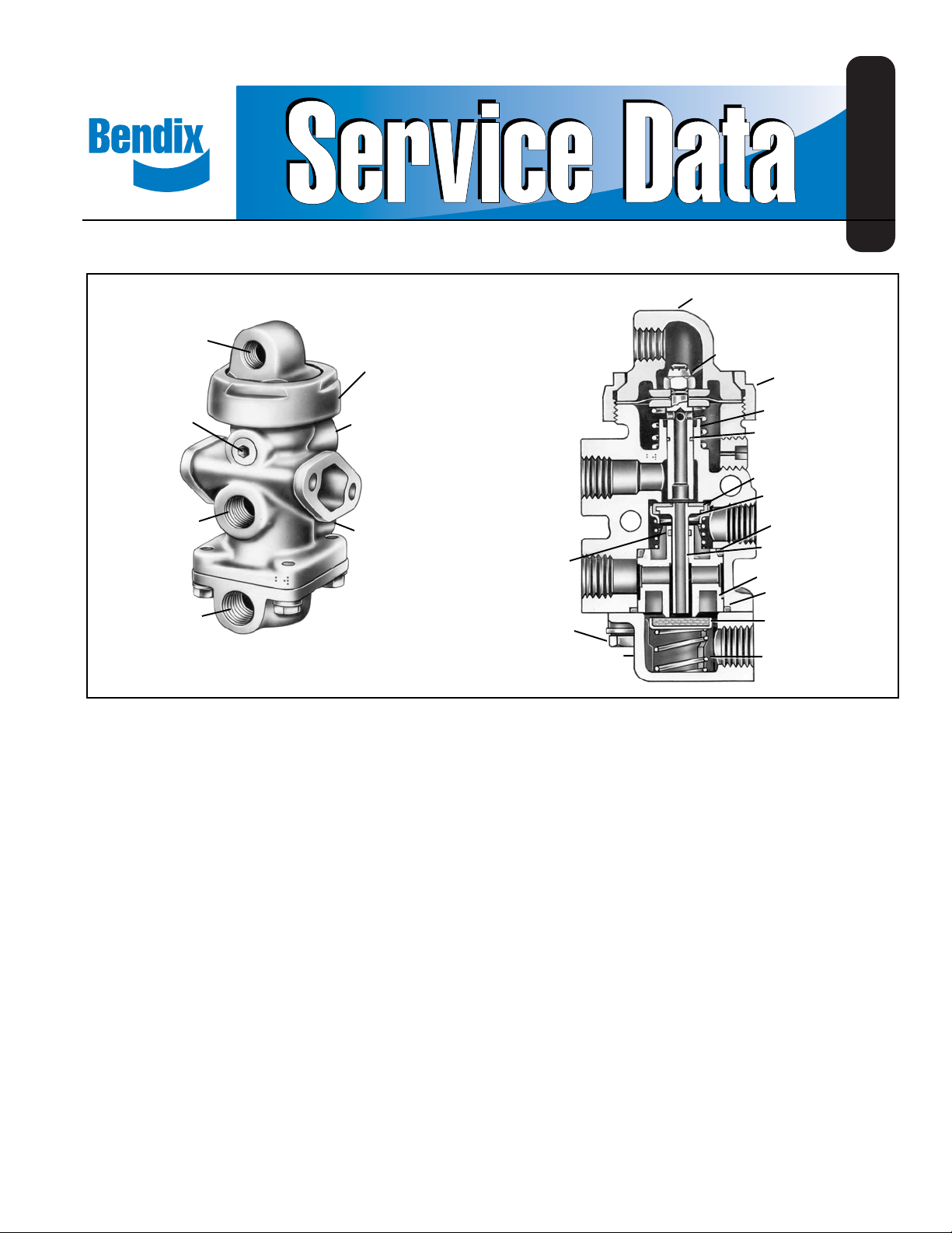
Bendix® TP-2™ Tractor Protection Valve
SD-03-3651
CONTROL CAP (13)
CONTROL PORT
CAP NUT
EXHAUST PORT
TRACTOR
SERVICE
PORT
TRACTOR
EMERGENCY
PORT
FIGURE 1 - TRACTOR PROTECTION SYSTEM
TRAILER
SERVICE
PORT
TRAILER
EMERGENCY
PORT
DESCRIPTION
The Bendix® TP-2™ tractor protection valve functions as a
set of remote controlled cut-out cocks, protecting the tractor
air supply should a loss of air occur in the trailer side
(delivery) of the valve. The TP-2™ valve is a three line system
as compared to the TP-3™ valve which is a two line system.
The valve is normally piped as shown in Figure 2. Lines
delivering service and supply (emergency) pressure to the
trailer are routed through the valve. A third control Iine comes
from the on-off control valve in the cab.
With the control valve in the “normal” (on) position and
reservoir pressure at approximately 50 psi, the valve will
open and service and emergency air is permitted to pass
through the valve. With the control valve in the emergency
position (off) position the vaIve is closed and service and
emergency lines on the trailer (delivery) side of the valve
are open to atmosphere through the vaIve’s exhaust port.
The valve will automatically close and vent delivery lines to
atmosphere should air pressure drop below a safe operating
EXHAUST VALVE PLUNGER AND
DIAPHRAGM ASS’Y (14)
CAP NUT (12)
EXHAUST PLUNGER
SPRING (15)
O-RING (16)
VALVE
RETAINER (7)
SPRING (8)
O-RING (10)
SERVICE AND EXHAUST
(11) O-RING
VALVE SEAT (5)
(1) CAP SCREW
(2) COVER
VALVE (6)
O-RING (9)
EMERGENCY
VALVE (3)
EMERGENCY VALVE
SPRING (9)
minimum pressure (approx. 40 psi), thus retaining and
protecting the tractor air brake system against complete
loss of air.
NOTE: With a TP-2™ valve system it should be noted that
the pneumatic logic for the legally required automatic
function is incorporated in the TP-2™ valve whereas
in the current TP-3™ valve system the logic is in the
supply valve in the cab. Consequently a TP-2™ valve
should never be replaced by a TP-3™ valve unless
the on-off control valve in the cab is replaced with
either a PP-3™ or PP-7™ trailer supply valve.
OPERATION - NORMAL POSITION
With air pressure at approximately 50 psi at the control
port, the diaphragm and plunger assembly is depressed
and the plunger contacts the service and exhaust valve
surface sealing the exhaust passage through the center of
the plunger. Continued travel of the plunger moves the service
valve off its seat, opening the service passage from the
1
Page 2
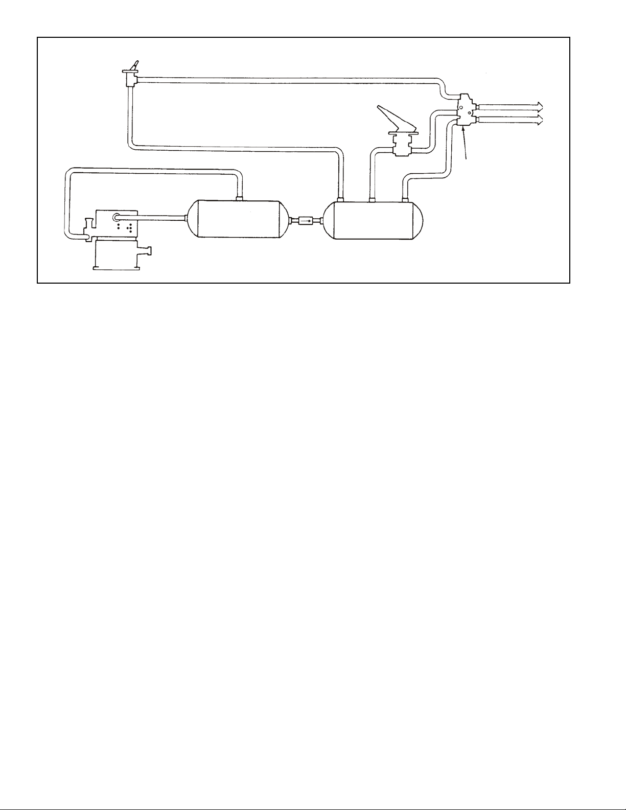
CONTROL
VALVE
COMPRESSOR
BRAKE
VALVE
TRAILER
SERVICE LINE
TRAILER
EMERGENCY
LINE
TRACTOR
PROTECTION
VALVE
NO. 1
RESERVOIR
FIGURE 2 - TRACTOR PROTECTION SYSTEM
tractor service port to the trailer service port. The stem of
the service and exhaust valve contacts the emergency valve,
sealing the exhaust passage. Continued travel of the service
and exhaust valve plunger moves the emergency valve off its
seat and allows air to flow from the tractor emergency port
to the trailer emergency port.
EMERGENCY POSITION
If air pressure in the control port (and on top of the diaphragm
and plunger assembly) drops below approximately 40 psi,
the combined forces of the exhaust plunger spring, the
service and exhaust valve spring and the emergency valve
spring will return the diaphragm and plunger assembly
allowing the service and exhaust valve and the emergency
valve to close. Further flow of air through either the service
or emergency ports is stopped. The loss in air pressure
which would precede such action would be indicated to the
driver, either visually or audibly by the low pressure warning
device, before such action would occur.
PREVENTIVE MAINTENANCE
Important: Review the Bendix Warranty Policy before
performing any intrusive maintenance procedures. A warranty
may be voided if intrusive maintenance is performed during
the warranty period.
No two vehicles operate under identical conditions; as a
result, maintenance intervals may vary. Experience is a
valuable guide in determining the best maintenance interval
for air brake system components. At a minimum, the TP-2
valve should be inspected every 6 months or 1500 operating
hours, whichever comes first, for proper operation. Should
the TP-2™ valve not meet the elements of the operational
NO. 2
RESERVOIR
CHECK
VALVE
tests noted in this document, further investigation and service
of the valve may be required.
OPERA TING AND LEAKAGE CHECK
NOTE: To make the following operating and leakage
checks,an accurate test gauge installed in spare
hose coupling is required. The vehicle dash gauge
should be checked for accuracy against the test
gauge prior to making these tests.
1. Block and/or hold the vehicle by means other than air
brakes during these test.
2. Drain vehicle reservoirs. Then close drain cocks.
3. Disconnect vehicle emergency and service hose
couplings and connect assembled hose coupling and
test gauge in tractor emergency hose coupling.
4. Start engine and build up system pressure.
5. As pressure in system builds up there should be no
pressure reading on test gauge. When system pressure
reaches 30 psi on dash gauge, make and hold a foot or
hand valve application and observe that no air escapes
at the open service hose coupling.
6. When system pressure reaches 40 to 60 psi, valve should
open and pressure reading show on test gauge. Allow
system to build up to 100 psi and shut off engine.
7. With soap solution coat exhaust port of the Tractor
Protection V alve. Leakage of a 1" bubble in 3 seconds
is permissible (175 SCCM).
™
8. Place the tractor protection control valve in the
“Emergency” position and note that emergency line
pressure drops promptly to zero on test gauge.
Disconnect coupling and test gauge.
2
Page 3

9. With soap solution:
A. Coat emergency line coupling. Leakage of a 1"
bubble in 5 seconds is permissible (100 SCCM).
B. Coat service line coupling. Make and hold a full hand
or foot valve application. Leakage of a 1" bubble in 5
seconds is permissible (100 SCCM).
10.Connect the coupling and test gauge to the emergency
line hose coupling. Place the tractor protection control
valve to “Normal” position. (If necessary , re-start engine
and build system pressure.) With ignition switch “on”
slowly drain tractor air brake system observing that low
pressure indicator occurs at prescribed pressure (normally
at approximately 60 psi) observe that the emergency
Iine will be vented by the tractor protection valve between
45 to 33 psi (test gauge will drop to 0 psi.)
If the TP-2™ tractor protection valve does not function as
described or if leakage is excessive, it is recommended
that it be replaced with a new or remanufactured unit, or
repaired with genuine Bendix parts, available at Bendix
outlets.
REMOVING AND INSTALLING
REMOVING
1. Block and/or hold vehicle by a means other than air
breaks. Drain air system reservoirs.
2. Identify lines and hoses so that correct lines are
reconnected to proper ports when reinstalling.
3. Remove lines; remove valve.
INSTALLING
1. Mount valve, checking to make certain control cap is
properly positioned. If it is necessary to re-position cap,
refer to No. 3 of “Assembly Instructions.”
2. Connect lines making certain proper lines are
connected to correct ports.
DISASSEMBLY
Important: Mark position of control port and tractor
emergency port location in relation to body in such a manner
that mark will not be obliterated during cleaning of parts.
Three (3) springs in valve should be carefully marked as to
their proper location in valve as valve is disassembled.
1. Remove four (4) cap screws (1) Figure 1, lock washers,
and cover (2) from valve.
2. Remove emergency valve (3) and emergency valve
spring (4) from cover.
3. Remove valve seat (5) service and exhaust valve (6),
valve retainer (7), spring (8).
4. Remove o-rings (9), (10), and (11).
5. Remove cap nut (12) and control cap. (13).
6. Remove exhaust valve plunger and diaphragm assembly
from body. (14).
7. Remove exhaust plunger spring (15) from body.
8. Inspect bores in valve body to be sure they are not
damaged or out of round. Clean body , control cap and
cover.
CLEANING AND INSPECTION
1. Clean all metal parts in mineral spirits and dry them
completely.
2. Inspect all parts for excessive wear or deterioration.
Inspect valve seats for nicks or burrs. Check the valve
spring for cracks or corrosion.
3. Inspect the bores of the valve housing for deep scuffing
or gouges.
Replace all parts that were discarded and any parts not
found to be serviceable during inspection, using only genuine
Bendix replacement parts.
ASSEMBL Y
Before assembling the TP-2™ valve, lubricate all o-rings,
o-ring grooves, body bores and rubbing surfaces with Bendix
silicone lubricant (Pc. No. 291 126) or equivalent.
NOTE: When using pipe thread sealant during assembly
and installation, take particular care to prevent the
sealant from entering the valve itself. Apply the
sealant beginning with the second thread back from
the end.
1. Place in vise with control cap end up. Install o-ring (16)
in groove in the stem of the exhaust valve plunger and
diaphragm assembly (14).
2. Install exhaust plunger spring (15) in valve body and
install exhaust plunger and diaphragm assembly (14).
IMPORTANT: Both sides of diaphragm and clamping
surfaces of body and control cap must be
free of grease. Plunger should be a neat
sliding fit in bore.
3. Position control cap (13) and cap nut (12). Position control
cap to desired port angle (as marked during
disassembly). Install a short (4-6") 1/4" pipe nipple in
control port of cap. Apply pressure firmly on cap, holding
in position with pipe nipple and firmly tighten cap nut to
approximately 50 ft. lbs.
It is important that the cap not be allowed to turn while
tightening the cap nut. Remove pipe nipple from control
port.
4. Place valve in vise with control cap down.
5. Install o-ring (10) in valve body (smaller of two o-rings).
3
Page 4

6. Preassemble the following parts before installing in valve:
a. Install valve seat o-ring (11) in small bore of valve
seat making certain it is properly seated in groove.
Install spring (8) (the heavier of the two remaining
springs) over protrusion on small bore end of valve
seat.
b. Install valve retainer (7) on service and exhaust valve
(6). Install stem of service and exhaust valve through
center of spring and into small bore of valve seat.
7. Carefully install preassembled parts in body and hold in
place.
8. Position o-ring (9) in groove of body.
9. Position emergency valve spring (4) in cover (2) and place
emergency valve (3) (metal side of valve in contact with
spring) on top of spring.
10. Install cover (2) in desired port position (as marked during
disassembly.) Check to be certain o-ring (9) and
emergency valve (3) are in position.
11. Install cap screws and lockwashers and tighten to
approximately 100 in. lbs.
TESTING REBUILT TP-2™ TRACTOR
PROTECTION VALVE
Performance tests as outlined in “Operating and Leakage
Checks” section.
WARNING! PLEASE READ AND FOLLOW
THESE INSTRUCTIONS TO AVOID
PERSONAL INJURY OR DEATH:
When working on or around a vehicle, the following
general precautions should be observed at all times.
1. Park the vehicle on a level surface, apply the
parking brakes, and always block the wheels.
Always wear safety glasses.
2. Stop the engine and remove ignition key when
working under or around the vehicle. When
working in the engine compartment, the engine
should be shut off and the ignition key should be
removed. Where circumstances require that the
engine be in operation,
be used to prevent personal injury resulting from
contact with moving, rotating, leaking, heated or
electrically charged components.
3. Do not attempt to install, remove, disassemble or
assemble a component until you have read and
thoroughly understand the recommended
procedures. Use only the proper tools and observe
all precautions pertaining to use of those tools.
4. If the work is being performed on the vehicle’s air
brake system, or any auxiliary pressurized air
systems, make certain to drain the air pressure from
all reservoirs before beginning
vehicle. If the vehicle is equipped with an AD-IS
air dryer system or a dryer reservoir module, be
sure to drain the purge reservoir.
5. Following the vehicle manufacturer’s
recommended procedures, deactivate the electrical
system in a manner that safely removes all
electrical power from the vehicle.
6. Never exceed manufacturer’s recommended
pressures.
7. Never connect or disconnect a hose or line
containing pressure; it may whip. Never remove a
component or plug unless you are certain all
system pressure has been depleted.
8. Use only genuine Bendix® replacement parts,
components and kits. Replacement hardware,
tubing, hose, fittings, etc. must be of equivalent
size, type and strength as original equipment and
be designed specifically for such applications and
systems.
9. Components with stripped threads or damaged
parts should be replaced rather than repaired. Do
not attempt repairs requiring machining or welding
unless specifically stated and approved by the
vehicle and component manufacturer.
10. Prior to returning the vehicle to service, make
certain all components and systems are restored to
their proper operating condition.
EXTREME CAUTION should
ANY work on the
™
BW1436 © 2004 Bendix Commercial Vehicle Systems LLC. All rights reserved. 3/2004 Printed in U.S.A.
4
 Loading...