

Page 1
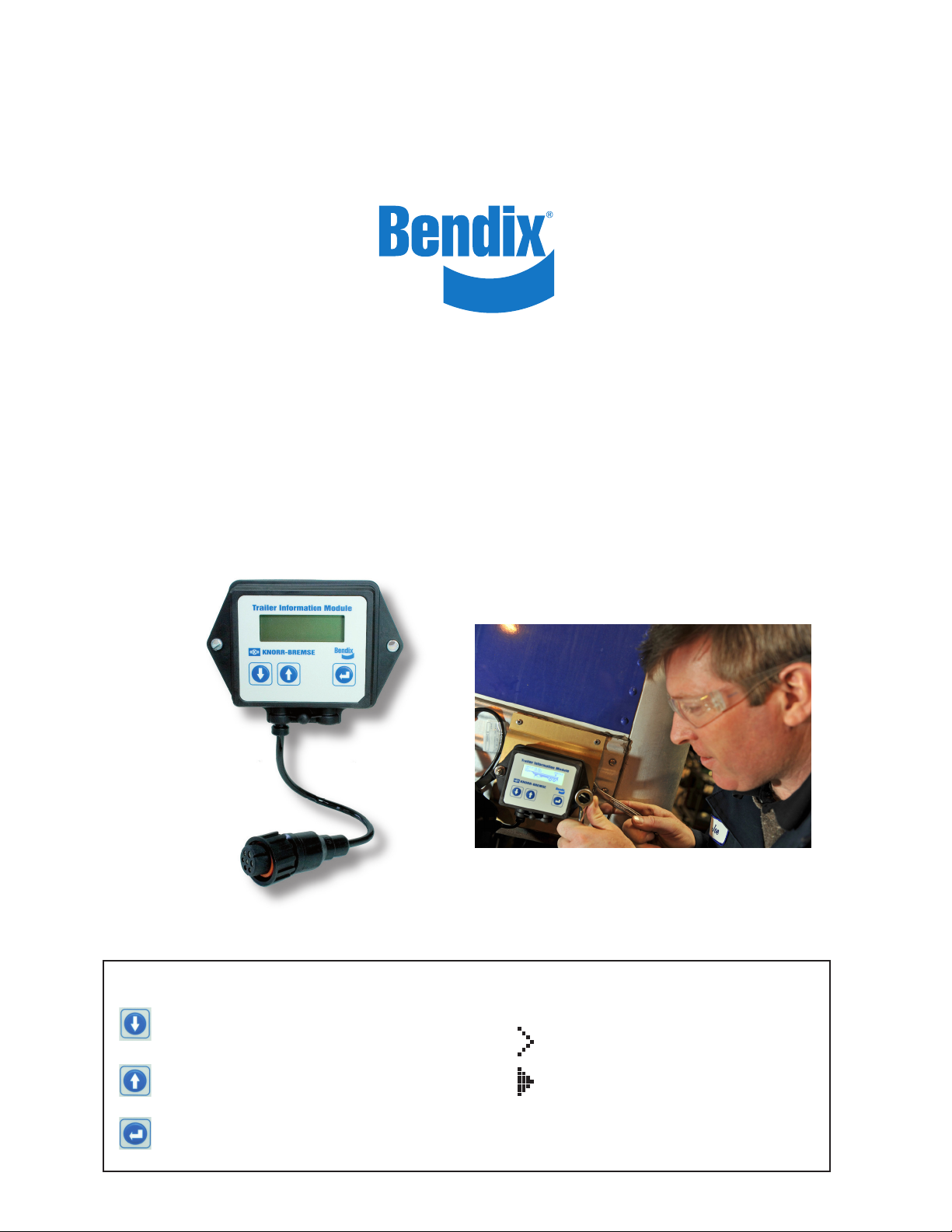
Bendix® Trailer Information Module (TIM™) G2
User Manual
User Manual
Navigation Buttons
Moves menu cursor down. Short hold jumps down one position, long hold
jumps to end of list (Exit).
Moves menu cursor up. Short hold jumps up one position, long hold jumps to
top of list.
Selects menu item at cursor position.
Cursor Function display
Menu point has no sub menu.
Menu point contains a sub menu or an item that may be modifi ed.
Navigation Buttons and Functionality
User Manual
Navigation Buttons
Moves menu cursor down. Short hold jumps down one position, long hold
jumps to end of list (Exit).
Moves menu cursor up. Short hold jumps up one position, long hold jumps to
top of list.
Selects menu item at cursor position.
Navigation Buttons and Functionality
User Guide
Press to move the cursor down one level.
Hold down to jump to the final level. (Exit)
Press to move the cursor up one level.
Hold down to jump up to the top of the list.
Select the chosen menu item.
Using the Navigation Buttons
The cursor is at a point with no sub menu.
The cursor is at a point with a sub menu or
an item that may be modified.
Page 2

DISPLAYS
With the ignition “ON”
The display is automatically activated. All menus are
available.
™
Bendix TIM
™
TABS-6
DISCLAIMER
For information
only! Press any key
to continue.
or
SUPPLY: 11.9V 58368LB
ODO: 127MI
or or
Initial Menu
<Active DTCs >
ODO: 127mi
Load Rear: 58420lb
Inst. Test Missing
Advanced ABS
or
Scroll until
“Main Menu”
TPMS symbol
(where used)
Initial Menu
Inst. Test Missing
TPMS Info
Main Menu
Exit
Main Menu
Stored DTCs
Distance & Serv.
Operating Info
System Info
With the ignition “OFF”
The display is off, push any navigation button for one second to
activate the display. Only limited menus are available.
Initial Menu
<Active DTCs >
ODO: 127mi
or or
DISCLAIMER
For information
only! Press any key
to continue
or
BATTERY MODE
For information
only! Values are
read from memory!
or or
Bendix TIM
™
TABS-6
Advanced ABS
or
™
Main Menu
Exit
Scroll until “Main Menu”
Main Menu
Stored DTCs
Distance & Serv.
Operating Info
ECU Info
+
SAFE MAINTENANCE PRACTICES
WARNING! PLEASE READ AND FOLLOW
THESE INSTRUCTIONS TO AVOID PERSONAL
INJURY OR DEATH:
When working on or around a vehicle, the following general precautions
should be observed at all times:
1. Park the vehicle on a level surface, apply the parking brakes, and
always block the wheels. Always wear safety glasses. Where
specically directed, the parking brakes may have to be released,
and/or spring brakes caged, and this will require that the vehicle be
prevented from moving by other means for the duration of these tests/
procedures.
2. Stop the engine and remove ignition key when working under or
around the vehicle. When working in the engine compartment, the
engine should be shut off and the ignition key should be removed.
Where circumstances require that the engine be in operation,
EXTREME CAUTION should be used to prevent personal injury
resulting from contact with moving, rotating, leaking, heated or
electrically charged components.
3. Do not attempt to install, remove, disassemble or assemble a
component until you have read and thoroughly understand the
recommended procedures. Use only the proper tools and observe
all precautions pertaining to use of those tools.
4. If the work is being performed on the vehicle’s air brake system,
or any auxiliary pressurized air systems, make certain to drain the
air pressure from all reservoirs before beginning ANY work on the
vehicle. If the vehicle is equipped with a Bendix® AD‑IS® air dryer
system or a dryer reservoir module, be sure to drain the purge
reservoir.
5. Following the vehicle manufacturer’s recommended procedures,
deactivate the electrical system in a manner that safely removes all
electrical power from the vehicle.
6. Never exceed manufacturer’s recommended pressures.
7. Never connect or disconnect a hose or line containing pressure; it
may whip. Never remove a component or plug unless you are certain
all system pressure has been depleted.
8. Use only genuine Bendix® brand replacement parts, components
and kits. Replacement hardware, tubing, hose, ttings, etc. must
be of equivalent size, type and strength as original equipment and
be designed specically for such applications and systems.
9. Components with stripped threads or damaged parts should be
replaced rather than repaired. Do not attempt repairs requiring
machining or welding unless specically stated and approved by the
vehicle and component manufacturer.
10. Prior to returning the vehicle to service, make certain all components
and systems are restored to their proper operating condition.
11. For vehicles with Automatic Traction Control (ATC), the ATC function
must be disabled (ATC indicator lamp should be ON) prior to
performing any vehicle maintenance where one or more wheels on
a drive axle are lifted off the ground and moving.
Page 3

MENU OVERVIEW
Initial Menu Main Menu
Repeat until
Trailer Information Module
<Active DTCs >
ODO: Omi
Load Rear: lb
Inst. Test Missing
<Active DTCs >
ODO: 0mi
Load Rear: lb
Inst. Test Missing
TPMS Info
2
3
Main Menu
Exit
“Main Menu”
Trailer Information Module
+
1
Stored DTCs
Distance & Serv.
Operating Info
System Info
Stored DTCs
Distance & Serv.
System Config
Operating Info
System Info
ECU Info
TIM Info
Exit
Stored
DTCs
Active DTCs:
<none>
DTCs:
Inactive
<none>
Clear DTCs
Exit
Date Based
Year:
Month:
Day:
Save & Exit
Exit
Distance & Serv.
ODO: mi
Trip: mi
Reset Trip
Srv Date:
Srv mi:
Set Next Service
Exit
Set Next Service
Date Based
Distance Based
Exit
Distance Based
Srv mi:
Save & Exit
Exit
System Config.
ABS Config.:
ECU Orient.:
RSP:
Exit
Operating Info
Info Total
Info Period
Exit
Info Total
ABS Events
RSP Interventions
Brake History
System Powering
Exit
TPMS Setup
Enter conf. Mode
Learn Sensor
Delete Sensor
Vehicle param.
Axle param.
Altitude comp:
Change password
Leave conf. Mode
Exit
3
5
5
5
5
5
6
5
5
System Info
TPMS Setup
Load Info
Pressure Info
Tilt Angle:
Wheel Speeds
Air Gap Speeds
Installation Test
Exit
Info Period
Period mi:
ABS Events:
RSP Interventions
Brake History
System Powering
Reset Period Data
Exit
Load Info
Front Axle Group
4
Bogie Load:
Rear Axle Group
Exit
3
4
Set LCD Contrast
LCD Contrast:
Save & Exit
Exit
Pressure Info
Dem P4:
Dem CAN:
Susp P42:
Pcyl P21:
Pcyl P22:
Res P1:
Exit
ECU Info
Part num:
SW:
Exit
Installation Test
Start Inst. Test
Install Check
Reserv. Press
S-A Sensor:
S-E Sensor:
S-C Sensor:
S-D Sensor:
S-F Sensor:
S-B Sensor:
Demand Press:
Tilt Angle:
Exit
TIM Info
Lang.:
Set LCD Contrast
Manufacturing Info
Exit
Manufacturing Info
Part num:
K001966XXXXXX
SW:
Serial:
ManufDate:
Exit
Wheel Speeds
S-A Sensor:
S-E Sensor:
S-C Sensor:
4
S-D Sensor:
4
S-F Sensor:
S-B Sensor:
Exit
4
4
Language
English (US)
N.Am. French
N.Am. Spanish
Exit
4
4
4
4
Airgap Speeds
S-A Sensor:
S-E Sensor:
S-C Sensor:
S-D Sensor:
S-F Sensor:
S-B Sensor:
Exit
4
4
4
4
RSP Intervention
Test Puls:
Step 1:
Step 2:
Step 3:
Exit
Appl vs Dem Values
<22psi:
22-36psi:
36-58psi:
>58psi:
Exit
Brake History
Appl vs Dem Values
Over Pressures
Exit
Over Pressures
Dem >130psi:
Res >130psi:
Exit
System Powering
ConstPower:
Stop Lamp:
Exit
Enter conf. Mode
Password:
Match password
Exit
1
Displayed only if active faults are available
2
Displayed only if installation test is missing
3
Displayed onlyifTirePressure Monitoring System (TPMS) is configured
4
Displayed only if included by vehicle ABS configuration
5
Displayed onlyif TPMS configuration mode entered
6
Displayed onlyif TPMS configuration mode not entered
6
Vehicle param.
FAL% CIP:
SAL % CIP:
Over Temp:
Exit
5
Change password
Password:
New passw.:
Save new passw.
Exit
5
Menu choices in green are not available in BATTERY MODE
Page 4

Initial Menu
a) Setting next service distance to
Reset Trip
Srv Date 18-01-10
Srv Mi: 6240mi
Set Next Service
Active DTCs:
S-C O/C.
S-D O/C.
Module Error
Main Menu
Stored DTCs
Distance & Serv.
Operating Info
System Info
+
1x
Date Based
Distance Based
Exit
Srv Mi: 0mi
Save & Exit
Exit
+
5x
+
1x
Srv Mi: 6250mi
Save & Exit
Exit
NOTE: “*” inactive, buttons and
revert to normal function
+
1x
Next service
distance has been
succesfully set in
ECU.
Indicates cursor buttons and
are now used to change ‘mi’ values
“
*
”
Srv Mi:
*
0mi
Save & Exit
Exit
2x
= 6250 mi
+
END
Main Menu
Stored DTCs:
Distance & Serv.
Operating Info
System Info
Overview of DTC
S-C Open circuit or
Shorted to Battery
DTC:
000D00
+
1x
DTC Detail
Scroll
Occurrence count:
4
First detection:
0mi
Scroll
Main Menu
System Info
ECU Info
TIM Info
Exit
+
Scroll to “TIM Info”
Lang.: US English
Scr Saver: Load
Set LCD Contrast
Manufacturing Info
US English
N.Am. French
N.Am. Spanish
Exit
+
1x
Langue: N.Am. French
Eco ecran Charger
Régl Contraste LCD
Info Fabricant
Info Fabricant
Test Affichage
Test Touche
Sortie
Scroll to “Sortie” (Exit)
END
2008-03-15 19:43.44
Last detection:
0mi
2008-03-31 10:11.47
END
6,250 miles (mi)
EXAMPLES
b) Display current Diagnostic
Trouble Code (DTC) status
c) Changing the language
default
d) Installation test
<Active DTCs>
ODO: 127mi
Load Rear: 58420lb
Inst. Test Missing
Scroll to “Inst. Test Missing”
Installation test
is missing! To
start it browse to:
Main Menu->
Start Inst. Test
Install. Check:
Reserv. Press:
S-C Sensor:
SECURE Trailer
against movement!
During this test
all its brakes may
+
3x
Scroll and follow
instructions on the
screen
all its brakes may
be released automatically! Press
ENTER to confirm
matically! Press
ENTER to confirm
you have secured
the Trailer.
Confirm that all
non connected
ports are plugged
then press ENTER.
Confirm that pneumatic connections
are secure, then
press ENTER.
2x
= Confirm
= Confirm
= Confirm
Confirm that
cables are securely
clipped, then
press ENTER.
Confirm that wheel
speed sensors have
been set, then
press ENTER.
Confirm that the
Truck‘s parking
brake is applied
then press ENTER.
Confirm that the
Trailer‘s parking
brake is NOT active
then press ENTER.
BW2867 © 2011 Bendix Commercial Vehicle Systems LLC, a member of the Knorr‑Bremse Group. 10/11. All Rights Reserved.
= Confirm
= Confirm
= Confirm
= Confirm
(if reservoir pressure > 6Bar)
Start Inst. Test
Install. Check:
Reserv. Press:
S-C Sensor:
Install. Check:
Reserv. Press:
S-C Sensor:
S-D Sensor:
Overview of wheel
location, “Confirm”
2x
Accelerate selected
wheel to 3mph
2x
Overview of wheel
location, “Confirm”
Accelerate selected
wheel to 3mph
Reserv. Press:
S-C Sensor:
S-D Sensor:
Demand Press:
S-C Sensor:
S-D Sensor:
Demand Press:
Tilt Angle:
Installation test
has been successfully executed.
Please switch igni-
fully executed.
Please switch ignition OFF-ON to
memorize status.
Start Inst. Test
Install. Check:
Reserv. Press:
S-C Sensor:
Fully apply the brake
pedal, then release it
o
< 5
TEBS mounting angle
within tolorance
2x
END
 Loading...