

Page 1
®
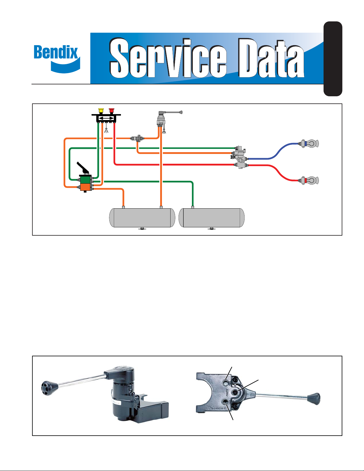
Bendix® TC-2™ Trailer Control Brake Valve
BENDIX®
MV-3®
CONTROL
VALVE
BRAKE
VALVE
DOUBLE
CHECK
VALVE
TC-2™
BRAKE
VALVE
SD-03-813
EMERGENCY HOSE
TRACTOR
PROTECTION
VALVE
SERVICE HOSE
FRONT AXLE
RESERVOIR
FIGURE 1 - BENDIX® TC-2™ TRAILER CONTROL BRAKE VALVE TYPICAL PIPING DIAGRAM
DESCRIPTION
The Bendix® TC-2™ trailer control brake valve is a hand
operated control valve which features graduated air
REAR AXLE
RESERVOIR
The TC-2 brake valve is not intended for use as a parking
control valve and should not be used for that purpose.
OPERATION
pressure control. The most common application is the
control of trailer brakes independent of tractor brakes;
however, the valve may be used wherever a handcontrolled pressure graduation operation is needed.
Two types of valves are available. The handle operated
valve is normally mounted within reach of the driver. A
typical installation is a steering column mount. The remote
APPLYING
When the handle or actuating lever is moved in a clockwise
direction from the released position, force is exerted on the
pressure graduating spring through the action of the cam
and cam follower. The force of the spring on the piston
causes it to move down.
operated type valve is connected to the operating handle
by a linkage rod.
DELIVERY PORT
SUPPLY PORT
FIGURE 2 - EXTERIOR VIEW
EXHAUST PORT
1
Page 2

The exhaust seat, which is in the center of the piston,
contacts the exhaust valve and closes the exhaust passage
in the piston. The continued downward movement of the
piston moves the inlet valve off its seat. Reservoir air
pressure fl ows by the open inlet valve and out the delivery
port.
HOLDING
The air pressure that fl ows by the open inlet valve also
becomes effective on the bottom area of the piston. As
the force of the air pressure beneath the piston balances
the force of the depressed graduating spring above, the
piston lifts slightly and the inlet valve returns to its seat.
The exhaust valve remains seated so that the fl ow of air
through the valve is stopped and air pressure in the service
line is held.
LEAKAGE TEST
Locate the exhaust port or exhaust line and apply a soap
solution. (It is common practice to connect a line from
the valve exhaust port to a location remote from the
immediate driver’s area.) With the valve in the released
position, exhaust leakage should not exceed a 1" bubble
in 5 seconds (100 sccm).
With the valve fully applied, leakage at the exhaust
should not exceed a 1" bubble in 3 seconds (175 sccm).
If the valve does not function as described, or leakage is
excessive, it is recommended that it be replaced with a
new or remanufactured unit, or repaired with genuine parts
available at an authorized Bendix outlet.
REMOVING AND INSTALLING
RELEASING
When the handle (or operating lever) is moved in a
counterclockwise direction, the force above the piston is
decreased. The air pressure beneath will then lift the piston,
moving it away from the exhaust valve. With the exhaust
passage open, air pressure in the service line will exhaust
out the exhaust port of the valve.
PREVENTIVE MAINTENANCE
Important: Review the warranty policy before performing
any intrusive maintenance procedures. An extended
warranty may be voided if intrusive maintenance is
performed during this period.
Because no two vehicles operate under identical
conditions, maintenance and maintenance intervals will
vary. Experience is a valuable guide in determining the
best maintenance interval for any one particular operation.
Visually check for physical damage to the brake valve such
as broken air lines and broken or missing parts.
Every three (3) months, 25,000 miles, or 900 operating
hours, perform Operating and Leakage Tests.
REMOVING
1. Block and hold the vehicle by means other than the air
brakes.
2. Drain the air brake system.
3. If the valve is a remote-operated type, disconnect the
operating mechanism.
4. Disconnect the air lines from the valve.
5. Remove the mounting clamp bolts, clamp, and then the
valve.
INSTALLING
1. Check and clean the air lines to the valve.
2. The operating mechanism for the remote-type valve
should be checked for functionally and for proper
adjustment.
3. Mount the valve with the clamp and mounting bolts.
4. Tighten the mounting bolts evenly to approximately 200
inch pounds torque (3/8-16 bolt torque 180-220 inch
pounds.)
5. If the valve is a remote-operated type, re-connect the
operating mechanism.
DISASSEMBLY
SERVICE CHECKS
OPERATING TEST
Connect an accurate test gauge to a delivery port. When
the Bendix® TC-2™ valve handle is moved to the fully
applied position, the gauge should register full reservoir
pressure. NOTE: Some valves may be preset to deliver
lower than reservoir pressure; however, the standard valves
generally used on tractors are set to deliver full reservoir
pressure. Intermediate positions should deliver proportional
intermediate pressures. Upon release, the gauge should
immediately register zero.
2
HANDLE OPERATED VALVE
1. Drive out the spiral pin and remove the handle, head,
and head seal o-ring.
2. Remove the handle o-ring.
3. For remote-operated type valve: Remove the set screw,
head and head seal o-ring.
4. Remove the adjusting ring lock washer.
5. Remove the cap screws that hold the body and cover
together; separate the cover from the body.
6. Remove the gasket and graduating spring.
7. Remove the cam and cam follower from the cover.
8. Unscrew and remove the adjusting ring.
Page 3

Adjusting Ring
Lock Washer
Head
Cam Follower
O-Ring
Spiral Pin
Knob
Adjusting Ring
Cam
Cover
Gasket
Piston
O-Ring
Body
Piston
Return Spring
Delivery
Port
FIGURE 3 - BENDIX® TC-2™ SECTIONAL VIEW
9. Remove the piston and piston return spring from the
body.
10. Remove the piston o-ring.
11. Remove the inlet and exhaust insert screws and lock
washers, then the insert and o-ring seal.
12. The inlet and exhaust valve insert can be disassembled
if desired or necessary.
13. Insert an object, such as a cap screw , in the supply port
to hold the inlet valve on its seat.
14. Depress the exhaust valve guide and spring; remove
the exhaust valve.
15. Remove the stem with inlet valve from the inlet seat
and remove the inlet valve from the stem.
Supply
Port
Exhaust
Port
Head
O-Ring
Graduating Spring
CLEANING AND INSPECTION OF PARTS
1. Clean all metal parts in mineral spirits.
2. Wipe all rubber parts clean.
3. Inspect the valve seats for nicks or burrs.
4. Check all springs for distortion, cracks, and corrosion.
5. All rubber parts should be inspected for wear or
deterioration.
6. Replace all parts not considered serviceable, during
their inspection, with genuine Bendix replacement
parts. Refer to the Quick Reference Catalog (BW1 1 14)
for service parts and kits. To order or download this
catalog visit the Bendix website at www.bendix.com.
Handle
Exhaust
Valve
Spring
Stem
Inlet Valve
TC-2™ Brake
Valve Insert
ASSEMBLY
Prior to assembly , lubricate the body and cover bores, cam
and cam follower, piston o-ring, and cover top with Dow
Corning® 55-M pneumatic grease (Bendix piece number
291126).
1. Press the inlet valve on the stem. A little water in the
boot valve or some soap on the stem will make it easier
to press on the inlet valve.
2. Place the stem with the inlet valve installed in the inlet
seat. Insert an object, such as a cap screw, to hold the
inlet valve up against its seat.
3. Position the spring and the exhaust valve guide.
4. Depress the guide and spring, then press the exhaust
valve on the stem.
5. Place the seal o-ring over the insert seat and – with
the cap screws and lock washers – install the inlet and
exhaust insert in the body. The recommended torque
on the insert cap screws is 60 to 80 inch pounds.
6. Install the piston return spring.
7. Install the piston o-ring on the piston and install the
piston in the body.
8. Install the adjusting ring in the cover and screw it down
until it is fl ush with the top of the cover.
9. Place the cam follower and cam in the cover.
10. Position the graduating spring and gasket in the body.
3
Page 4

1 1. Connect the body to the cover; tighten the cap screws
evenly and torque to 75-95 inch pounds.
12. Install the adjusting ring lock washer , be sure to align the
lock washer with the cover to prevent cross-threading.
13. Install the head seal o-ring and head.
14. Instal l the set screw in the head of remote-operated type
valves. At this stage, before installing the handle and
spiral pin of a handle-operated type valve, if facilities
are available the rebuilt valve should be tested and
adjusted. If the facilities are not available, the valve
can be tested on the vehicle.
TESTING REBUILT BENDIX® TC-2™ BRAKE
VALVE
Perform “Operating and Leakage Tests” as outlined in
“Service Checks” section.
ADJUSTMENT
Generally, the TC-2
™
trailer control brake valve should
deliver full reservoir pressure; however, there are a few
exceptions in special applications.
1. If the delivered pressure is below specifi ed fi nal delivery
pressure, it can be adjusted by removing the head and
the adjusting ring lock washer and rotating the adjusting
ring clockwise to raise the delivery pressure.
2. If the delivery pressure is above the specifi ed fi nal
delivery pressure, it can be lowered by rotating the
adjusting ring counterclockwise.
A spanner wrench can be used to rotate the adjusting ring,
but if such a wrench is not available, the adjusting ring
can be turned with a small screwdriver inserted in one of
the inner notches of the ring. Turning the adjusting ring
one notch will raise the delivered pressure approximately
5 psi.
4
BW1430 © 2011 Bendix Commercial Vehicle Systems LLC, a member of the Knorr-Bremse Group • 11/2011 • All Rights Reserved
 Loading...