

Page 1
®
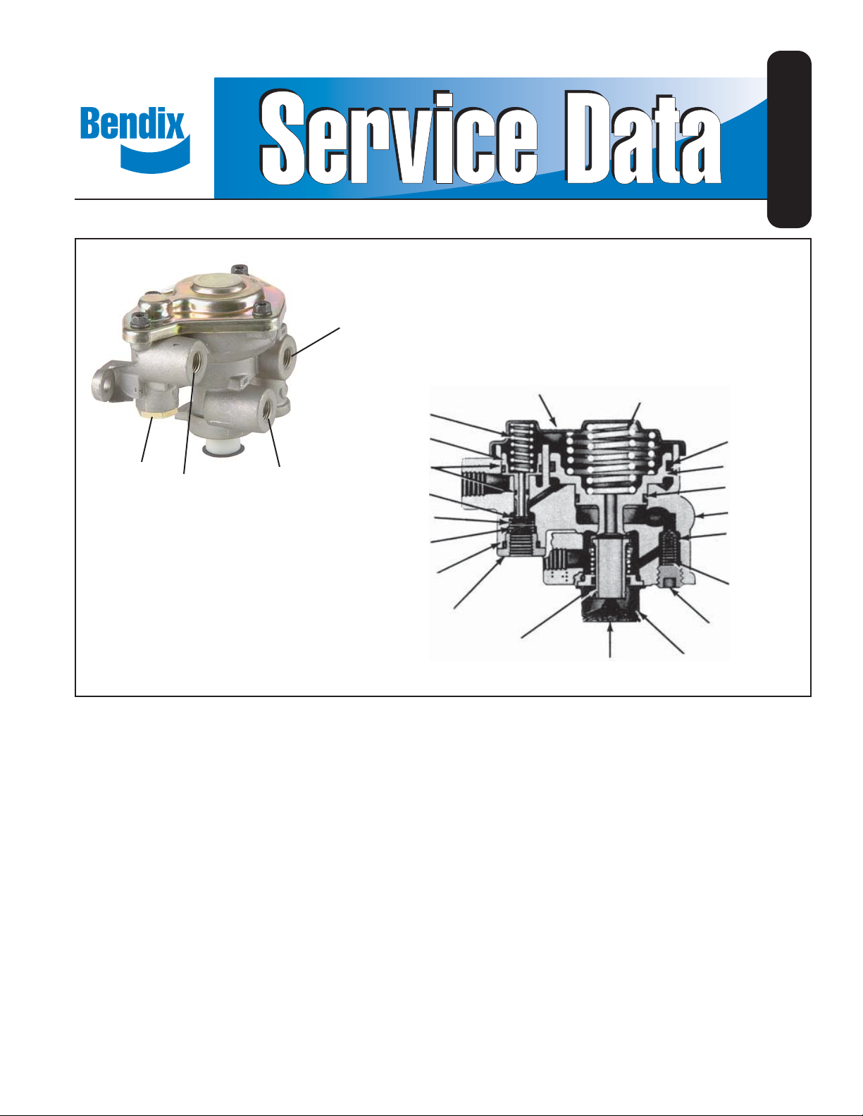
Bendix® SR-1™ Spring Brake Valve
1/4 P.T.
DELIVERY
SD-03-4508
PISTON SPRING
(14)
PISTON (15)
1/4 P.T.
CONTROL
1/4 P.T.
RES. #1
FIGURE 1 - BENDIX
1/4 P.T.
SUPPLY
®
SR-1™ VALVE EXTERIOR AND SECTIONAL VIEW
PISTON O-RINGS
(16)
VALVE (12)
VALVE SPRING (11)
VALVE STOP (10)
O-RING (9)
CAP NUT (8)
DESCRIPTION:
The Bendix® SR-1™ spring brake valve is used in dual
or “split” air brake systems equipped with spring brake
actuators. The function of the SR-1 valve is to supply a
specifi c, limited hold-off pressure to the spring brakes, and
in the event of the loss of No. 1 service air pressure, to
modulate the spring brakes through the use of the service
brake valve.
The valve has four identifi ed 1/4" N.P.T.F. ports and a
diaphragm protected exhaust port. Two 5/16" diameter
holes are provided in the integral mounting bracket of the
valve body. The SR-1 valve must be mounted with the
exhaust port down toward the road surface.
COVER (13)
INLET &
EXHAUST
VALVE (7)
PISTON SPRINGS
DIAPHRAGM
(6)
(14)
O-RING
(LARGE)
(18)
PISTON (17)
O-RING
(SMALL) (19)
BODY
CHECK
VALVE (4)
CHECK
VALVE SPRING (2)
PIPE PLUG
(1)
EXHAUST
COVER (5)
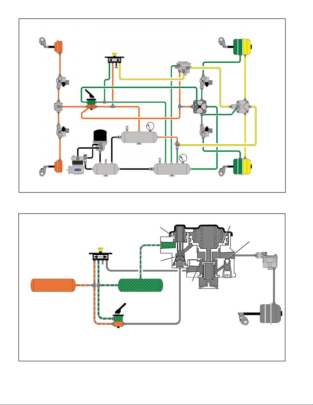
OPERATION - INITIAL AIR SYSTEM CHARGE
Air fl owing from the No. 1 reservoir only enters the reservoir
port of the SR-1 valve. This air remains under piston A as
system pressure builds. With No. 1 reservoir pressure
below approximately 55 P.S.I. the spring above piston A
forces it into contact with inlet and exhaust valve A causing
the exhaust to seal and the inlet to open. Refer to Figure 3.
With air system pressure above approximately 55 P.S.I. in
No. 1 & 2 service reservoirs, piston A has moved against
the force of the spring above it, allowing the inlet of valve A
to close and opening the hollow exhaust passage through
piston A. Refer to Figure 4.
1
Page 2
BRAKE
CHAMBER
BRAKE
VALVE
PARK
CONTROL
VALVE
SLACK
ADJUSTER
SPRING
BRAKE
QUICK
RELEASE
VALVE
MODULATOR
FIGURE 2 - SYSTEM SCHEMATIC
PARK
CONTROL
VALVE
#2 SERVICE
RESERVOIR
DOUBLE
CHECK
VALVE
SUPPLY
DOUBLE
CHECK VALVE
#2 SERVICE
RESERVOIR
#1 SERVICE
RESERVOIR
PISTON A
INLET &
EXHAUST A
#1 SERVICE
RESERVOIR
™
R-8
VALVE
INLET
&
EXHAUST
B
EXHAUST
®
R-14
RELAY
VALVE
PISTON B
CHECK VALVE
®
R-14
RELAY
VALVE
BRAKE
VALVE
FIGURE 3 - RESERVOIRS CHARGING - BELOW 55 P.S.I.
2
SPRING
BRAKE
Page 3
PARK
CONTROL
VALVE
PISTON A
INLET &
EXHAUST A
PISTON B
CHECK VALVE
R-14
RELAY
VALVE
®
#2 SERVICE
RESERVOIR
DOUBLE
CHECK
VALVE
FIGURE 4 - RESERVOIRS CHARGING - ABOVE 55 P.S.I.
PARK
CONTROL
VALVE
#2 SERVICE
RESERVOIR
DOUBLE
CHECK
VALVE
#1 SERVICE
RESERVOIR
EXHAUST A
#1 SERVICE
RESERVOIR
PISTON A
INLET &
INLET
&
EXHAUST
B
INLET
&
EXHAUST
B
EXHAUST
EXHAUST
PISTON B
CHECK VALVE
R-14
RELAY
VALVE
SPRING
BRAKE
®
BRAKE
VALVE
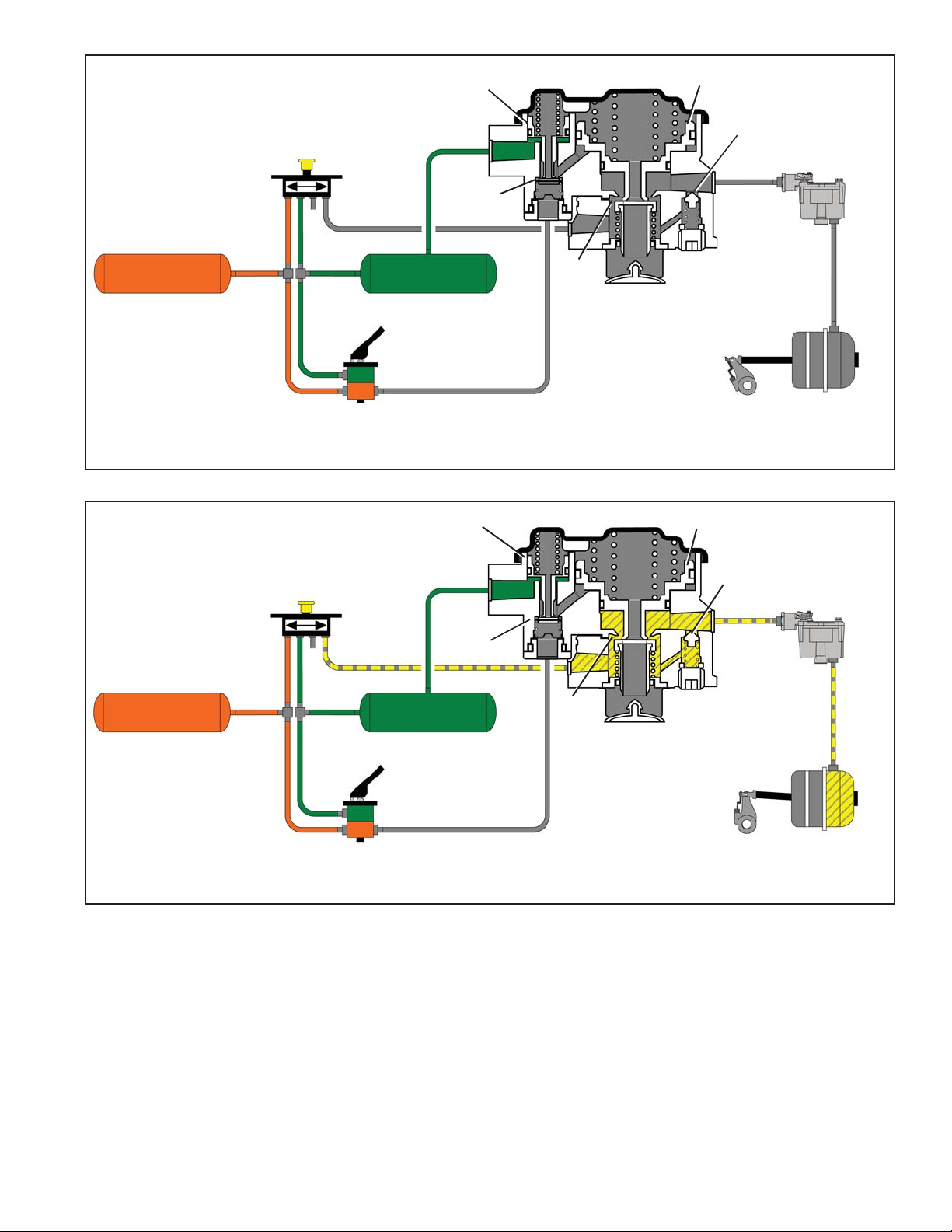
FIGURE 5 - PARKING BRAKE SUPPLY DELIVERY LESS THAN 95 P.S.I.
OPERATION - CHARGING SPRING BRAKE
ACTUATORS LESS THAN 95 PSI
With the air brake system charged and the dash valve
pushed in, air enters the Bendix
Air entering the supply port fl ows past inlet and exhaust
valve B to the underside of piston B and out the delivery
port of the SR-1 valve to the Bendix® R-14® parking relay
valve then to the emergency air connection at the spring
brake actuator. Note that the springs above piston B force
it into contact with inlet and exhaust valve B. In the position
®
SR-1™ valve supply port.
OPERATION - CHARGING SPRING BRAKE
ACTUATORS ABOVE 95 PSI
When air pressure beneath piston B is approximately
95* P.S.I., piston B rises slightly, against the force of the
springs above it, allowing the inlet of valve B to close. The
exhaust through valve B remains closed. The closing of
the inlet portion of valve B retains approximately 95* P.S.I.
in the hold- off cavity of the spring brake actuators while
allowing full air system pressure to build elsewhere. Refer
to Figures 5 and 6.
shown the exhaust is closed and the inlet is open.
SPRING
BRAKE
3
Page 4

PISTON A
PISTON B
PARK
CONTROL
VALVE
#2 SERVICE
RESERVOIR
DOUBLE
CHECK
VALVE
FIGURE 6 - PARKING BRAKE SUPPLY DELIVERY EQUAL TO OR GREATER THAN 95 P.S.I.
PARK
CONTROL
VALVE
#1 SERVICE
RESERVOIR
BRAKE
VALVE
INLET &
EXHAUST A
PISTON A
INLET &
EXHAUST A
INLET
&
EXHAUST
B
EXHAUST
PISTON B
CHECK VALVE
®
R-14
RELAY
VALVE
SPRING
BRAKE
CHECK VALVE
®
R-14
RELAY
VALVE
#2 SERVICE
RESERVOIR
DOUBLE
CHECK
VALVE
FIGURE 7 - NORMAL SERVICE APPLICATION
#1 SERVICE
RESERVOIR
BRAKE
VALVE
*Note: Other spring brake hold-off pressures are
supplied according to the vehicle manufacturer’s
specifi cations. 95 P.S.I. was chosen only for the
purpose of explanation.
OPERATION - NORMAL SERVICE RESERVOIRS
1 & 2 CHARGED
When a service application is made by actuating the dual
brake valve, air from the No. 2 delivery circuit is delivered
from the brake valve to the control port, and is stopped at
the closed inlet of valve A. No movement of the internal
components of the Bendix
Air from the No. 1 delivery circuit of the dual brake valve
actuates the service section of the spring brake actuators.
Refer to Figure 7.
®
SR-1™ valve takes place.
INLET
&
EXHAUST
B
EXHAUST
SPRING
BRAKE
OPERA TION - SERVICE APPLICA TION WITH LOSS
OF NO. 2 RESERVOIR PRESSURE
In the event air pressure is lost in the No. 2 reservoir,
the No. 1 reservoir and the parking control valve will be
protected via the double and single check valves in the
air system. A service application of the foot brake valve
in this situation results in little or no air being delivered
from the No. 2 delivery circuit to the control port of the
SR-1 valve. No movement of the SR-1 valve internal
components takes place. Braking is assured because the
No. 1 service reservoir is protected by a check valve and
the No. 1 delivery circuit of the dual brake valve will apply
the service section of the spring brake actuators.
4
Page 5

PARK
CONTROL
VALVE
PISTON A
INLET &
EXHAUST A
PISTON B
CHECK VALVE
®
R-14
RELAY
VALVE
#2 SERVICE
RESERVOIR
FIGURE 8 - SERVICE APPLICATION - LOSS OF #2 RESERVOIR
#2 SERVICE
RESERVOIR
DOUBLE
CHECK
VALVE
PARK
CONTROL
VALVE
DOUBLE
CHECK
VALVE
#1 SERVICE
RESERVOIR
PISTON A
INLET &
EXHAUST A
#1 SERVICE
RESERVOIR
INLET
&
EXHAUST
B
INLET
&
EXHAUST
B
EXHAUST
EXHAUST
PISTON B
CHECK VALVE
R-14
RELAY
VALVE
SPRING
BRAKE
®
FIGURE 9 - SERVICE APPLICATION - LOSS OF #1 RESERVOIR
OPERA TION - SERVICE APPLICA TION WITH LOSS
OF NO. 1 RESERVOIR PRESSURE
If air pressure in the No. 1 service reservoir falls below
approximately 55 P.S.I., the pressure beneath piston A is
insuffi cient to resist the spring force above and piston A moves
into contact with valve A. Initial contact between piston A
and valve A closes the hollow exhaust passage of piston A.
Continued movement of the piston opens the inlet of valve A.
The No. 2 service reservoir and the park control valve are
protected from pressure loss by the action of the double
check valve.
SPRING
BRAKE
When a service application of the dual brake valve is
made, air delivered from the No. 2 delivery circuit of the
dual brake valve enters the Bendix
®
SR-1™ valve control
port. Air entering the control port moves past the inlet of
valve A and is conducted through a passage in the body to
the underside of piston B. The air pressure moves piston
B up, opening the exhaust of valve B. When the exhaust
of valve B opens, air pressure trapped in the emergency
section of the spring brake actuator is allowed to escape,
resulting in an emergency brake application. The air
pressure released from the spring brake is proportional
to the air pressure delivered to the control port of the
SR-1 valve by the No. 2 delivery of the dual brake valve.
5
Page 6

PISTON A
PISTON B
PARK
CONTROL
VALVE
INLET &
EXHAUST A
#2 SERVICE
RESERVOIR
FIGURE 10 - P ARK APPLICA TION
DOUBLE
CHECK
VALVE
#1 SERVICE
RESERVOIR
OPERATION - PARKING
If both systems #1 and #2 are intact and the park control
valve is placed in the “park” or exhaust position, the Bendix
SR-1™ valve supply of air pressure and the air pressure in
the spring brake actuator cavities is exhausted. The single
check valve in the SR-1 valve assists this exhaust of air
pressure by allowing the air below piston B to fl ow back
out the open exhaust of the park control valve. When air
pressure below piston B has dropped suffi ciently , piston
B moves down, opening the inlet of valve B and providing
an additional exhaust passage for air exhausting through
the SR-1 valve from the spring brakes.
®
PREVENTIVE MAINTENANCE
Important: Review the Bendix Warranty Policy before
performing any intrusive maintenance procedures. A
warranty may be voided if intrusive maintenance is
performed during the warranty period.
No two vehicles operate under identical conditions, as
a result, maintenance intervals may vary. Experience is
a valuable guide in determining the best maintenance
interval for air brake system components. At a minimum,
the SR-1 valve should be inspected every 6 months or
1500 operating hours, whichever comes fi rst, for proper
operation. Should the SR-1 valve not meet the elements
of the operational tests noted in this document, further
investigation and service of the valve may be required.
CHECK VALVE
®
R-14
RELAY
VALVE
INLET
&
EXHAUST
EXHAUST
B
SPRING
BRAKE
1. Place parking control valve in the “park” position.
Observe that the spring brake actuators apply promptly .
In the delivery port of the valve install a test gauge
known to be accurate. Place the parking control valve
in the “release” position. Observe that the spring brake
actuators release fully.
2. With the parking control valve in the “release” position,
note the gauge pressure reading. (Check the vehicle
manual for the correct spring brake actuator hold-off
pressure.) If the pressure reading is incorrect, the valve
must be repaired or replaced.
3. Place the parking control valve in the “park” position,
the gauge reading should drop to zero promptly . A slow
release of pressure may indicate faulty operation of the
single check valve (within the modulating valve.)
4. Place the parking control valve in the “release” position.
Locate the number one service reservoir and drain it
completely.
Apply the foot brake valve several times and note that
the pressure reading on the gauge decreases each
time the foot brake valve is applied. After several
applications, pressure on the gauge will drop to the
point where release of the spring brake actuators will
no longer occur.
SERVICE CHECKS
OPERATING CHECKS
Block all wheels and hold by means other than vehicle
brakes. Charge air brake system to governor cut-out
pressure.
6
Page 7

LEAKAGE CHECK
With the air system fully charged and the parking control
valve in the “release” position, coat the exhaust port and
around the valve corner with a soap solution. Slight leakage
is permitted.
®
If the Bendix
as described previously, or leakage is excessive, it is
recommended that it be repaired or replaced with a genuine
Bendix service replacement valve.
Note: A maintenance kit for the SR-1 spring brake valve is
available from any authorized Bendix outlet. All parts
necessary for minor repair are included.
SR-1™ spring brake valve does not function
REMOVAL
1. Prior to removing the SR-1 valve, apply the parking
brakes and drain all the vehicle reservoirs.
2. Identify all air lines before disconnecting.
3. Remove the two mounting bolts from the SR-1 valve
and remove the valve.
DISASSEMBLY (REFER TO FIGURE 1)
1. Remove the socket head pipe plug (1).
2. Remove the check valve spring (2) and the check valve
(4).
3. Remove the two phillips head screws and remove the
exhaust cover (5).
4. Separate the exhaust diaphragm (6) from the cover.
5. Remove the inlet and exhaust valve assembly (7).
6. Remove the inlet and exhaust valve cap nut (8) and
separate the cap nut o-ring (9).
7. Remove the valve stop (10) valve spring (11) and inlet
and exhaust valve (12).
8. Remove the four phillips head screws and lockwashers
that secure the cover to the body . Caution: the cover is
under a spring load, and should be held while removing
the screws.
9. Remove the cover (13) and the three piston springs
(14). Note: Some SR-1 valve piece numbers have one
large piston spring.
10. Remove the small piston (15) and the small and large
o-rings (16).
11. Remove the large piston (17). Remove piston o-rings
(18) & (19).
CLEANING & INSPECTION
1. Inspect all parts for excessive wear or deterioration.
2. Inspect the valve seats for nicks or burrs.
3. Check the springs for cracks or corrosion.
4. Replace all rubber parts and any part not found to be
serviceable during inspection. Use only genuine Bendix
replacement parts.
ASSEMBLY (REFER TO FIGURE 2)
Prior to assembly of the SR-1 spring brake valve, lubricate
all o-rings, o-ring grooves, and piston bores with Bendix
silicone lubricant BW-650-M piece number 291126.
Note: All torques specifi ed in this manual are assembly
torques and can be expected to fall off, after
assembly is accomplished. Do not retorque after
initial assembly torques fall.
1. Assemble the check valve (4), and valve spring (2) and
install in body.
2. Apply pipe sealant to the socket head pipe plug (1)
and install in the body . T ighten to 130-170 inch pounds
torque.
3. Install inlet and exhaust valve assembly (7) in valve
body.
4. Secure the exhaust cover (5) with two 10-24 phillips
head screws and lockwashers. Tighten to 20-30 inch
pounds torque.
5. Install exhaust diaphragm (6) into the exhaust cover.
6. Place inlet exhaust valve (12) in the body. Install the
valve spring (11) and valve stop (10).
7. Install o-ring (9) on cap nut and install cap nut (8) in
body. Tighten to 100-125 inch pounds torque.
8. Install the small and large o-rings (16) on the small
diameter piston (15) and install piston in the body.
9. Install large o-ring (18) and small o-ring (19) on the
large diameter piston and install piston in the body.
10. Install the piston springs (14) in their respective pistons.
11. Secure the cover to body using four 1/4"-20 phillips
head screws and lockwashers. Tighten to 50-80 inch
pounds torque.
TESTING THE REBUILT BENDIX® SR-1™ SPRING
BRAKE VALVE
Test the rebuilt SR-1 spring brake valve by performing the
operation and leakage test outlined in the “Service Checks”
section of this manual.
7
Page 8

BW1589 © 2012 Bendix Commercial Vehicle Systems Company LLC, a member of the Knorr-Bremse Group • 5/2012 • All Rights Reserved
8
 Loading...