

Page 1
Bendix® SL-3™ & SL-4™ Stop Light Switch
SD-06-1800
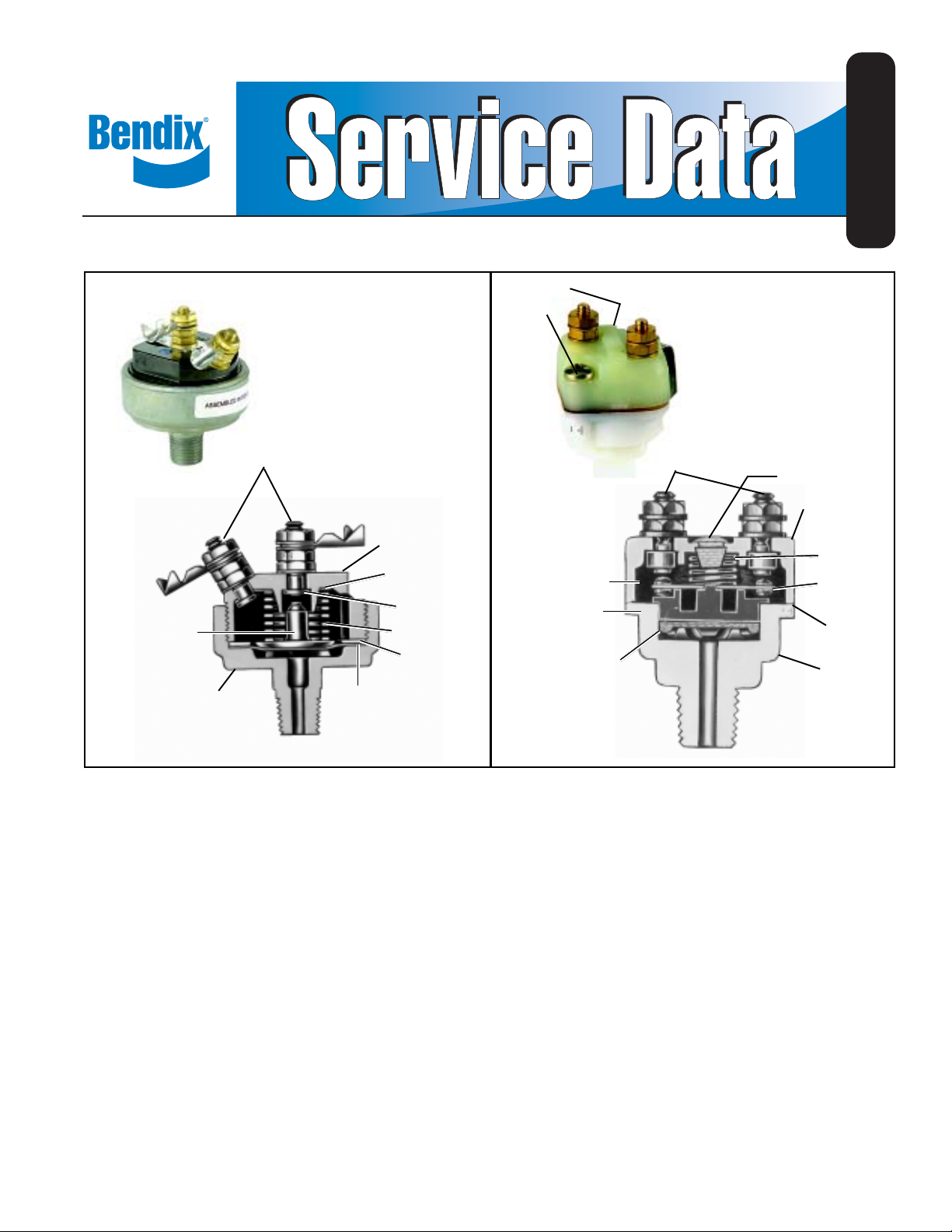
MACHINE
SCREWS
7
TERMINAL 2
COVER 1
TERMINAL
CONNECTOR 7
CONTACTS
PLUNGER 4
BODY
FIGURE 1 - SL-3™ STOP LIGHT SWITCH
DIAPHRAGM 6
SPRING 3
WASHER 5
DESCRIPTION
The stop light switch is an electro-pneumatic switch and
operates in conjunction with the brake valve and stop lights
by completing the electrical circuit when a brake application
is made.
CONTACT
PISTON
13
O-RING
DIAPHRAGM 14
FIGURE 2 - SL-4
TERMINAL 9
™
STOP LIGHT SWITCH
VENT PLUG 10
COVER 8
SPRING 11
CONTACT
STRIP 12
GASKET
15
BODY
PREVENTIVE MAINTENANCE
Important: Review the Bendix Warranty Policy before
performing any intrusive maintenance procedures. A warranty
may be voided if intrusive maintenance is performed during
the warranty period.
OPERATION
When a brake application is made, air pressure from the
brake valve enters the cavity below the diaphragm. At
approximately 5 psi, the air pressure underneath the
diaphragm overcomes the force of the spring and moves
the piston or plunger until the contact points close completing
the stop light electrical circuit and lighting the stop lights.
No two vehicles operate under identical conditions; as a
result, maintenance intervals may vary. Experience is a
valuable guide in determining the best maintenance interval
for air brake system components. At a minimum, the SL-3™/
SL-4™ switch should be inspected every 6 months or 1500
operating hours, whichever comes first, for proper operation
and electrical connections. Should the SL-3™/SL-4™ switch
not meet the elements of the operational tests noted in this
document, further investigation and service of the valve may
be required.
1
Page 2

TESTING FOR SERVICEABILITY
OPERATING TEST
1. Apply the brake valve and note that the stop light lights
before the delivery pressure reaches 7 psi.
2. Release the brake valve and note that the stop light goes
“off”.
LEAKAGE TEST
1. With the brakes fully applied, no leakage is permitted at
the stop light switch. If the stop light switch does not
function as described or if leakage is excessive, it is
recommended that it be replaced with a new unit or
repaired with genuine Bendix parts available at authorized
Bendix parts outlets.
CLEANING AND INSPECTION
Clean all metal parts in cleaning solvent. Wipe rubber parts
dry with cloth.
Inspect contact points for pits or wear. If pitting is not too
severe, the points may be reconditioned by filing with a
distributor point file. If points cannot be reconditioned, they
should be replaced. The contact strip in the SL-4™ switch
may be turned over to use the other side of the contacts.
Check the spring for signs of deterioration; Replace if
discolored. The spring in the SL-3™ switch carries the current
of the electrical circuit involved; consequently , in the case of
excessive current, as might be caused by a short, the spring
will be overheated and ruined.
REMOVING
1. Disconnect electrical connections at the stop light switch.
2. Disconnect air line to the stop light switch.
3. Remove the stop light switch.
INSTALLING
1. Install in a convenient location for servicing.
2. Install with pipe tap pointing to the ground and keep it
high for adequate drainage.
3. Connect the stop light switch in series in the stop light
circuit.
4. Keep the stop light switch terminals away from frame
members to avoid grounding.
5. Connect the pipe tap to the brake chamber supply line
so that the stop light switch will operate whether the
foot or hand valve is applied.
DISASSEMBLY
(SL-3™ SWITCH)
1. Place hex portion of body in a vise.
2. Using a large end wrench on cover flats, turn cover (1)
in a counterclockwise direction and remove from body .
3. Remove terminal nuts, terminals (2) and terminal
connector (7) from cover.
4. Remove spring (3), plunger (4), washer (5) and
diaphragm (6) from body.
(SL-4™ SWITCH)
1. Remove two machine screws (7) and remove cover (8).
2. Remove terminal nuts and terminals (9) from cover.
3. Remove the vent plug (10) from cover.
4. Remove spring (1 1), contact strip (12), piston (13) and
o-ring diaphragm (14) from body .
Inspect cover and body. If cracked or damaged, replace.
Only genuine Bendix service parts should be used for
replacement.
ASSEMBLY
(SL-3™ Switch) (Figure 1)
1. Insert terminal screws (2) in cover (1), making sure the
terminal connector (7) is properly positioned.
2. Secure terminal screws with washers and nuts, or
terminal clips, as the case may be.
3. Place diaphragm (6) in body.
4. Position contact plunger (4) on diaphragm.
5. Position spring (3) on plunger.
6. Place washer (5) on diaphragm and screw cover (1)
into body. Torque to 30 foot pounds. Make certain the
vent hole in the cover is open.
(SL-4™ Switch) (Figure 2)
1. Position terminals (9) in cover (8) and secure with washers
and nuts or terminal clips. Place vent plug (10) in cover .
2. Place o-ring diaphragm (14) and piston (13) in body.
O-ring diaphragm should be installed with its flat side
adjacent to the piston.
3. Place gasket (15) in place on body and contact strip
(12) on piston (13).
4. Position cover assembly on gasket and secure with
machine screws. Torque to 20 inch pounds.
TEST OF REBUILT STOP LIGHT SWITCH
Both operating and leakage tests, as indicated under section
headed “Testing for Serviceability”, must be made after
rebuilding or repairing the stop light switch. The switch must
meet the following specifications;
1. No leakage is permissible at the stop light switch with
the brakes applied.
2. The stop light switch contact should close with not more
than 7 pounds of air pressure.
2
Page 3

PRECAUTIONARY NOTE:
WARNING! PLEASE READ AND FOLLOW
THESE INSTRUCTIONS TO AVOID
PERSONAL INJURY OR DEATH:
When working on or around a vehicle, the following
general precautions should be observed at all times.
1. Park the vehicle on a level surface, apply the
parking brakes, and always block the wheels.
Always wear safety glasses.
2. Stop the engine and remove ignition key when
working under or around the vehicle. When
working in the engine compartment, the engine
should be shut off and the ignition key should be
removed. Where circumstances require that the
engine be in operation, EXTREME CAUTION should
be used to prevent personal injury resulting from
contact with moving, rotating, leaking, heated or
electrically charged components.
3. Do not attempt to install, remove, disassemble or
assemble a component until you have read and
thoroughly understand the recommended
procedures. Use only the proper tools and observe
all precautions pertaining to use of those tools.
4. If the work is being performed on the vehicle’s air
brake system, or any auxiliary pressurized air
systems, make certain to drain the air pressure from
all reservoirs before beginning ANY work on the
vehicle. If the vehicle is equipped with an AD-IS
air dryer system or a dryer reservoir module, be
sure to drain the purge reservoir.
5. Following the vehicle manufacturer’s
recommended procedures, deactivate the electrical
system in a manner that safely removes all
electrical power from the vehicle.
6. Never exceed manufacturer’s recommended
pressures.
7. Never connect or disconnect a hose or line
containing pressure; it may whip. Never remove a
component or plug unless you are certain all
system pressure has been depleted.
8. Use only genuine Bendix® replacement parts,
components and kits. Replacement hardware,
tubing, hose, fittings, etc. must be of equivalent
size, type and strength as original equipment and
be designed specifically for such applications and
systems.
9. Components with stripped threads or damaged
parts should be replaced rather than repaired. Do
not attempt repairs requiring machining or welding
unless specifically stated and approved by the
vehicle and component manufacturer.
10. Prior to returning the vehicle to service, make
certain all components and systems are restored
to their proper operating condition.
11. For vehicles with Antilock T raction Control (ATC),
the ATC function must be disabled (ATC indicator
lamp should be ON) prior to performing any vehicle
maintenance where one or more wheels on a drive
®
axle are lifted off the ground and moving.
3
Page 4

4
BW1593 © 2006 Bendix Commercial Vehicle Systems LLC All rights reserved. 7/2006 Printed in U.S.A.
 Loading...