

Page 1

®
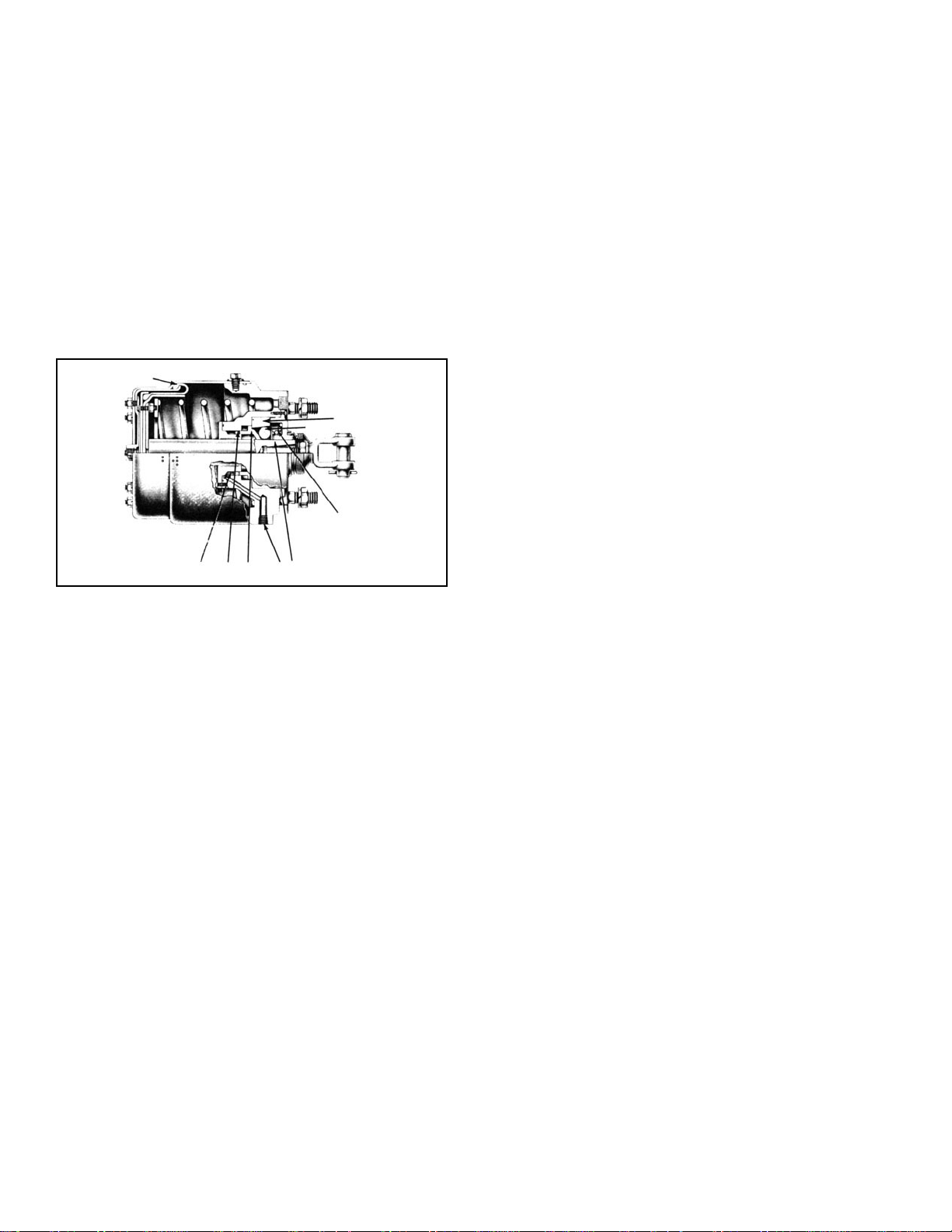
Bendix® DD-3™ & SD-3™ Safety Actuators
SD-02-4600
SERVICE
DIAPHRAGM
AUXILIARY
DIAPHRAGM
RETURN
SPRING
REAR
SEAL
FIGURE 1 - DD-3
SEPARATOR
™
SAFETY ACTUATOR
PUSH PLATE
& SHAFT
ASSY.
EXHAUST
DIAPHRAGM
LOCKING
PISTON
O-RING
GASKET
LOCKING
PISTON
CAP O-RING
ROLLER SPRING
FRONT SEAL
ROLLERS (8)
SPLASH PLATE
EMERGENCY
PORT
LOCKPORT
DRAIN SLOT
SERVICE PORT
FIGURE 2 - SD-3
™
SAFETY ACTUATOR
DRAIN SLOT
SERVICE PORT
LOCKING PORT
1
Page 2
DESCRIPTION
The DD-3™ and SD-3™ are air operated actuators with a
mechanical push shaft lock. The DD-3™ actuator (see Fig.
1) is a double diaphragm device which provides braking for
service, emergency, and parking. It is available in two sizes:
type 24 and type 30.
The SD-3™ actuator is a single diaphragm device used
primarily on off-highway vehicles. It provides service braking
and parking. It is available as a diaphragm type in type 30
(see Fig. 2) and in rotochamber configuration in type 36 and
50 (see Fig. 3).
The locking mechanism function is identical in all SD-3
and DD-3™ actuators.
OPERATION - DD-3™ ACTUATOR (FIG. 1) NORMAL RUNNING
For normal operation full reservoir pressure is applied
continuously at the lock port, keeping the rollers disengaged
and permitting the shaft to extend and retract unrestricted.
Applications may be made by means of applying air
pressure on either the service diaphragm or the auxiliary
diaphragm. The auxiliary diaphragm has about 80% of the
effective area of the service diaphragm.
EMERGENCY
The auxiliary diaphragm of the DD-3™ actuator may be
™
connected to an alternate source of air pressure thus
providing an emergency capability.
J
F
D
G
B
C
EAH
FIGURE 3
In normal operation, the SD-3
™
or DD-3™ safety actuator is
similar to a brake chamber or rotochamber. However, the
addition of a locking roller mechanism locks the push rod
in the extended position unless the rollers are held out of
place by the application of air pressure at the lock port A
(Fig. 3).
In the normal operating position, air pressure is applied to
lock port A and into cavity B. This pressure acting on piston
C moves it forward, contacting rollers D, pushing them up
ramp E. Spring G then holds rollers D between ramp E and
collar ramp F and away from push rod H. The push rod is
then free to move back and forth with the application and
release of service air pressure.
In the park position, air pressure is vented from lock port A
and cavity B, permitting piston C to move back. Spring G
forces rollers D against collar ramp F and push rod H.
During this sequence, a parking brake application has been
made with air pressure. However, if air pressure behind
diaphragm J is lost for any reason, push rod H will attempt
to move back to the released position but the wedge shape
of collar ramp F will force the rollers against the push rod,
thereby preventing any return movement of the push rod.
The brake application is now held mechanically and will be
maintained until air pressure is again applied to the lock
port. The rollers will be released when the push rod is slightly
extended with a service application.
2
PARKING
The DD-3™ actuator parking function is activated by releasing
the air pressure from the lock port and making a brake
application. The application may well be made from the same
alternate source as used for the emergency application. It
should preferably be made on the auxiliary diaphragm for
reasons which will be explained under “releasing.”
If the air application is released or leaks off, the shaft will
retract slightly and then be clamped by the wedging action
of the rollers. The brakes may now be considered to be
applied and to remain applied regardless of any exhaustion
of energy or loss of air pressure.
RELEASE OF PARKING APPLICATION
To release a parking application, air pressure in excess of
40 psi must be applied at the lock port and a brake application
slightly greater than the locked-in application must be made.
Thus if the park application is made with the auxiliary
diaphragm, an application of equal air pressure on the larger
area service diaphragm will provide the heavier application
required to free the lock rollers and release the park
application.
OPERATION - SD-3™ ACTUATOR (FIG. 3) NORMAL RUNNING
For normal operation full reservoir pressure is applied
continuously at the lock port, keeping the rollers disengaged
and permitting the shaft to extend and retract unrestricted.
In this mode, the SD-3™ actuator functions the same as a
standard brake chamber or rotochamber.
PARKING (SD-3™ ACTUATOR)
The SD-3™ actuator may be used for parking by releasing
the air pressure from the lock port and making a limited
application at a pressure somewhat less than the cut-in
pressure of the air governor. For instance, if the governor
cut-in pressure is 85 psi, the suggested parking pressure
would be 75 psi. As the application is released, the lock
mechanism will engage the shaft and retain the park
application.
Page 3

RELEASING (SD-3™ ACTUATOR)
To release the park application, air pressure in excess of 40
psi must be applied at the lock port and a service application
slightly greater than the locked-in application made. For
practical purposes, a full reservoir application should be made
and held for 5 seconds to produce sufficient forward motion
of the shaft to allow disengagement of the lock mechanism.
Various control systems are used to achieve the proper
sequence of control signals. Bendix brochure “Off Highway
Vehicle Braking System” (BW 1283) explains one such
system.
PREVENTIVE MAINTENANCE
GENERAL
Depending on experience and type of operation, the drain
slot in the actuator non-pressure plate should be checked
and cleaned of any restricting road grime, mud, ice, snow,
etc. Check or replace actuator boot if loose on the push
rod or if worn.
Brake should be adjusted at the slack adjuster as is
customary with standard brake chambers. Push rod travel
should be as short as possible without brakes dragging.
Excessive travel not only shortens the normal service life of
the diaphragm but gives slow braking response and wastes
air.
Push rod to slack adjuster alignment should be checked in
both the applied and released positions. The rod should
move out and return promptly without binding.
Check the angle formed by the slack adjuster arm and
push rod. It should be 90° or greater when the actuator is
in the applied or released position when brakes are properly
adjusted.
EVERY MONTH, 300 OPERATING HOURS, OR AFTER
8000 MILES
Check push rod travel, alignment and nuts for tightness.
Check hoses. (See slack adjuster for adjustment.)
Disassemble, inspect diaphragms and rubber parts, rod,
springs, and non-pressure plate. Replace all parts worn or
damaged. Check for proper operation before placing vehicle
in service.
REMOVING AND INSTALLING
Block and hold the vehicle by some means other than air
brakes.
REMOVING DD-3™ ACTUATOR
With the actuators in a released position, disconnect the
air lines to the service and auxiliary ports. Move the park
control valve to the park position which will exhaust the air
from the lock port. Disconnect the lock port line. Remove
yoke pin and back off slack adjuster. Remove mounting
nuts, then actuator.
REMOVING SD-3™ ACTUATOR
If the SD-3™ actuator is mounted on a vehicle with its own
air supply, the parking control should be placed in the release
position with the air system completely charged. Disconnect
the service port line. Move the park control valve to the park
position and disconnect the lock line. Remove the actuator
as above.
If the SD-3™ actuator is mounted on a trailer, with no air
supply present and in the applied position, completely drain
trailer reservoir. Remove delivery and lock port lines from
actuator. Release force from actuator by backing off slack
adjuster or mounting nuts or both. Remove actuator.
INSTALLING
IMPORTANT - DD-3™ and SD-3™ safety actuators must be
installed with the exhaust check valve down and the drain
slot pointing down.
Mount actuator to mounting bracket and tighten securely.
Fasten actuator push rod yoke to slack adjuster with yoke
pin. Lock yoke pin with cotter pin. The angle formed by the
push rod and slack adjuster arm should be greater than
90°.
Check for proper operation.
EVERY 3 MONTHS, 900 OPERATING HOURS, OR 25,000
MILES
When grease fitting is provided, grease with Lubriplate
“Aero” lubricant.
EVERY 12 MONTHS, 3600 OPERATING HOURS, OR
100,000 MILES
Connect air lines to actuator. Take care that the correct line
is installed in the correct port.
Adjust brakes.
DISASSEMBLY
1. Clean actuator exterior of all road grime and mark in
such a way so it can be assembled in the same manner.
2. Remove yoke and yoke lock nuts.
3. Remove splash guard, boot, felt breather, and gasket.
4. Remove auxiliary and service clamping ring nuts and
bolts.
3
Page 4

5. Spread clamping rings slightly, just enough to slip rings
off plates, It may be necessary to use a soft mallet to
break the clamping rings loose. If clamping rings are to
be reused, caution should be taken so they are not
distorted.
6. Remove auxiliary pressure plate, auxiliary diaphragm,
service pressure plate, service diaphragm (with
separator, if present). On SD-3™ actuators, pressure plate
and service diaphragm only.
7. Place non-pressure plate assembly on a smooth surface
with the push plate down.
8. Connect an air supply (shop air) line to the locking port.
Push down on the actuator non-pressure plate;
maintaining air pressure at the locking port. As the shaft
is unlocked (released), ease the non-pressure plate back
and remove the push plate and shaft assembly with push
rod and return spring.
9. While holding cap assembly down against roller spring
tension, completely remove four (4) machine screws,
release cap assembly, and remove.
10. Remove retainer from cap by turning in clockwise
direction until tabs of retainer line up with slots in cap.
Remove retainer spring and seal. Remove inner and
outer cap o-rings.
11. Remove roller spring (G), spring seat washer, and eight
(8) rollers (F) (Fig. 3).
12. Remove collar (E), piston (C), and piston o-ring. NOTE:
If necessary, apply air cautiously at the lock port to assist
in removal of the above parts.
13. Remove rear retaining spring by dislodging from groove
of plate and remove rear seal.
14. Inspect bearing in shaft bore on non-pressure plate,
and remove only if it shows signs of wear and is to be
replaced. The push rod should not be removed from
the shaft unless it is damaged and requires replacement.
To remove rod, place a heavy washer over the rod
against the shaft; position a spacer (short length of pipe)
and a second washer over the rod (and on top of the
spacer). Install yoke lock nut(s) and turn down with a
long-handled wrench, pulling the push rod from the shaft.
15. Remove exhaust check valve from non-pressure plate.
16. The studs in the non-pressure plate may be removed
and replaced if necessary.
CLEANING AND INSPECTION
1. Wash all metal parts in a good cleaning solvent and dry
thoroughly. It is generally recommended that all rubber
parts be replaced; however, any rubber parts that are
to be reused should be wiped dry.
2. Discard felt breather.
3. Inspect all parts for excessive wear or deterioration.
Particular attention should be given to the piston and
collar bores in the non- pressure plate. The air passage
from the lock port to piston bore should be checked for
restriction and cleaned; if necessary, remove the
inspection plug to thoroughly clean this passage.
4. Rollers should be carefully checked, and all rollers
replaced if one or more need replacing.
5. Check springs for cracks, distortion, or corrosion.
6. Replace all parts not considered serviceable during
these inspections.
ASSEMBLY
1. Line up parts as they were marked prior to assembly.
2. If the bearing in the non-pressure plate was removed, it
should be re-installed or replaced if necessary.
3. Lubricate piston and collar bores, shaft, piston o-ring,
piston and roller cavity liberally with “Never Seez”
lubricant (BW 404-M).
4. Position piston o-ring in piston bore, then piston with
smooth end down against o-ring.
5. Place collar in its bore (chamfer side down).
6. Coat rollers thoroughly and liberally with “Never Seez”
lubricant (BW 404-M) and place eight (8) rollers in
grooves formed by top of piston and collar ramp.
7. Pack roller cavity liberally with “Never Seez” lubricant
(BW 404-M).
8. Place roller spring seat washer on top of rollers.
9. Position cone-shaped roller spring on washer with
smaller end to washer.
10. Install o-rings in cap: small o-ring in inner bore, large
o-ring on outside of cap, making certain o-rings are
properly seated in grooves.
11. Place seal in bore of cap. Lip of seal should face front
of cap. Place retainer spring on seal, position retainer
on spring, compress spring, line up tabs on retainer to
slots on cap, and lock retainer on cap by turning 1/4
turn counterclockwise.
12. Position cap on roller spring. DRAIN HOLE IN CAP
SHOULD BE POSITIONED SO IT LINES UP WITH
DRAIN AREA of non-pressure plate. Press cap down
and hold while installing four (4) machine screws evenly
and securely. Install new felt breather.
13. Turn over non-pressure plate assembly and install rear
seal. Lip of seal faces non-pressure cavity. Install spring
retainer, making certain it is retained in groove of nonpressure plate.
14. Install push plate return spring (larger end down).
15. Position push plate and shaft over return spring and
press down so shaft moves through lock. The lock should
hold shaft position against return spring. If not, check
previous assembly procedure.
4
Page 5

16. (SD-3™ Actuator) Install diaphragm, pressure plate, and
clamping ring.
™
17. (DD-3
Actuator) The DD-3™ actuators are supplied with
two different diaphragm constructions. Figure 1 shows
one construction with a metal separator between the
service and auxiliary diaphragms. The separator snaps
over a bead on the service diaphragm. The service
diaphragm piece number for this assembly is 246371
for the type 30 and 246365 for the type 24.
An alternate design eliminates the separator in the type
30 and substitutes service diaphragm 292711 with a
special surface lubricant which eliminates the need for
the separator. This design has not been produced in
the type 24.
Still a third design was used for certain customers for a
short period, in which the service diaphragm and
separator were riveted together as an assembly. If this
construction is encountered, the diaphragm and
separator assembly should be discarded. The new
surface lubricated diaphragm 292711 may then be
installed, without a separator. A kit, piece number
265071, is available which includes one of the new
surface lubricated service diaphragm 292711 and one
auxiliary diaphragm 246675.
18. Install service diaphragm and separator (if used), service
pressure plate, and clamping ring.
19. Install auxiliary diaphragm, auxiliary pressure plate, and
clamping ring.
20. Tighten bolts on both clamping rings evenly and securely.
21. Install exhaust check valve.
22. If push rod was removed, replace with new rod and
new locking ring. Pack shaft cavity with BW 204-M
barium lubricant (piece number 240176 or piece number
246671). Install lock ring in groove on rod and press
rod in shaft cavity, making certain rod is locked in place
in shaft.
23. Install new gasket on non-pressure plate.
24. Install boot over cap assembly. Install splash plate over
boot.
Replenish air supply to auxiliary diaphragm. Operate control
valve to release parking application, then make a full service
application to complete release of actuators. The magnitude
of the service brake application to release the brakes may
vary on different vehicles due to compressor governor
settings. Normally a service application of approximately
70 psi should release the brakes.
™
OPERATING SD-3
ACTUATOR
With actuator in the released position, make several brake
applications and note that actuator applies and releases
properly.
Make a parking application, air pressure released from lock
port. Release air pressure from service diaphragm and
observe that actuators remain applied. Apply full reservoir
pressure on service diaphragm and on lock port. Release
application on service diaphragm and observe that actuator
releases properly.
LEAKAGE - SD-3
™
AND DD-3™ ACTUATOR
With system pressure up and actuators in the released
position, check drain slot and around the push rod boot
with a soapy solution to detect possible leakage past the
locking piston grommet.
Make and hold a service brake application and again check
the actuator drain slot or exhaust check valve for service
diaphragm leakage. Continue to hold the service application
and coat around the service and auxiliary diaphragm
clamping rings with the soapy solution to detect seal leakage.
DD-3™ ACTUATOR ONLY
Operate the park control valve to apply a park or emergency
application on the auxiliary diaphragm. Remove the hose
connection at the service diaphragm port and observe for
leakage which would indicate a failed auxiliary diaphragm.
The auxiliary diaphragm clamp should again be checked
for leakage while the auxiliary diaphragm is pressurized.
Should leakage be detected at the clamping rings in either
of the above tests, the clamping ring nuts should be tightened
evenly but only enough to stop leakage.
OPERATING AND LEAKAGE CHECKS
OPERATING - DD-3™ ACTUATOR
With the actuator in the released position, make several
brake applications and note that actuators apply and release
properly.
Operate parking control valve and observe that actuators
apply. While actuators are in a parking position, drain air
supply to auxiliary diaphragm and note that actuators remain
applied.
If the safety actuator does not function as described or
leakage is excessive, it is recommended that it be returned
to the nearest Bendix authorized distributor for a factory
reconditioned actuator under the repair exchange plan. If
this is not possible, the actuator can be repaired with genuine
Bendix parts.
5
Page 6

WARNING! PLEASE READ AND FOLLOW
THESE INSTRUCTIONS TO AVOID
PERSONAL INJURY OR DEATH:
When working on or around a vehicle, the following
general precautions should be observed at all times.
1. Park the vehicle on a level surface, apply the
parking brakes, and always block the wheels.
Always wear safety glasses.
2. Stop the engine and remove ignition key when
working under or around the vehicle. When
working in the engine compartment, the engine
should be shut off and the ignition key should be
removed. Where circumstances require that the
engine be in operation,
be used to prevent personal injury resulting from
contact with moving, rotating, leaking, heated or
electrically charged components.
3. Do not attempt to install, remove, disassemble or
assemble a component until you have read and
thoroughly understand the recommended
procedures. Use only the proper tools and observe
all precautions pertaining to use of those tools.
4. If the work is being performed on the vehicle’s air
brake system, or any auxiliary pressurized air
systems, make certain to drain the air pressure from
all reservoirs before beginning ANY work on the
EXTREME CAUTION should
vehicle. If the vehicle is equipped with an AD-IS
air dryer system or a dryer reservoir module, be
sure to drain the purge reservoir.
5. Following the vehicle manufacturer’s
recommended procedures, deactivate the electrical
system in a manner that safely removes all
electrical power from the vehicle.
6. Never exceed manufacturer’s recommended
pressures.
7. Never connect or disconnect a hose or line
containing pressure; it may whip. Never remove a
component or plug unless you are certain all
system pressure has been depleted.
8. Use only genuine Bendix
®
replacement parts,
components and kits. Replacement hardware,
tubing, hose, fittings, etc. must be of equivalent
size, type and strength as original equipment and
be designed specifically for such applications and
systems.
9. Components with stripped threads or damaged
parts should be replaced rather than repaired. Do
not attempt repairs requiring machining or welding
unless specifically stated and approved by the
vehicle and component manufacturer.
10. Prior to returning the vehicle to service, make
certain all components and systems are restored
to their proper operating condition.
™
6
BW1563 © 2004 Bendix Commercial Vehicle Systems LLC. All rights reserved. 4/2004 Printed in U.S.A.
 Loading...