

Page 1
Bendix Manual Slack Adjusters
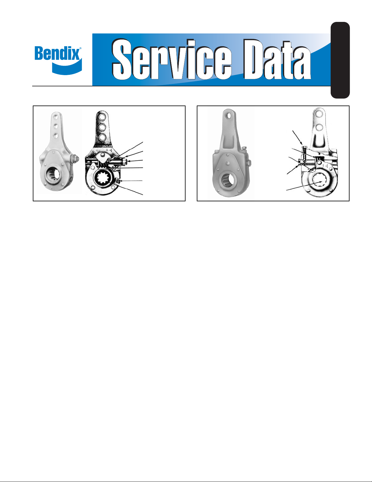
WORM GEAR
LOCK SLEEVE
ADJUSTING SCREW
(WORM SHAFT)
ADJUSTING GEAR
GREASE HOLE
SPLINE
FIGURE 1 - POSITIVE LOCK TYPE SLACK ADJUSTER
SD-05-1200
WORM SHAFT (LOCK
SCREW)
WORM GEAR
ADJUSTING
GEAR
ADJUSTING SCREW
(WORM SHAFT)
SPLINE
FIGURE 2 - BALL INDENT TYPE SLACK ADJUSTER
DESCRIPTION
In an s-cam type foundation brake, the final link between
the pneumatic system and the foundation brake is the slack
adjuster. The arm of the slack adjuster is fastened to the
push rod of the chamber with a yoke, and the slack adjuster
spline is installed on the brake cam shaft.
Primarily , the slack adjuster is a lever , converting the linear
force of the air chamber push rod into a torque which turns
the brake cam shaft and applies the brakes.
Standard slack adjusters contain four basic components;
the body, worm, gear and adjusting screw. The adjusting
screw is provided to adjust the slack caused by the wear of
the brake lining.
All slack adjusters utilize the worm and gear principle and,
fundamentally, differ only in torque limit specifications; A
type 20 slack adjuster has a limit of 20,000 inch pounds
torque, a type 30 slack adjuster has a limit of 30,000 inch
pounds torque, etc.
Slack adjusters are manufactured with various arm lengths
and various configurations; straight, offset, etc. to satisfy
various installation requirements. Splines are available in
several different types and sizes.
OPERA TION
When the brakes are applied, air pressure forces the air
chamber diaphragm and push rod to move; this rotates the
slack adjuster, which in turn rotates the cam shaft. This
causes the “S” cam to spread the brake shoes which contact
the brake drum.
When the brakes are released, air pressure is exhausted
from the air chamber. The chamber return spring and the
brake shoe return springs return the brake cam, cam shaft,
slack adjuster and chamber push rod to the released position.
ADJUSTING MECHANISM
The adjusting mechanism of a slack adjuster consists of an
adjusting screw (worm shaft), worm and slack adjuster worm
gear. T urning the adjusting screw nut on the end of the worm
shaft rotates the worm shaft and worm. The worm meshes
with and rotates the slack adjuster worm gear which is
connected to the brake cam by a splined cam shaft. The
turning of the slack adjuster worm gear rotates the cam
shaft and brake cam, spreading the brake shoes,
compensating for brake lining wear.
There are two types of adjusting mechanisms used on Bendix
slack adjusters currently manufactured. The light to medium
torque rated slack adjusters (Fig. 1) use a positive lock
mechanism consisting of a spring loaded lock sleeve, which
when positioned properly , engages the adjusting screw nut,
preventing the adjusting screw (worm shaft) from rotating.
The heavier torque rated slack adjusters (Fig. 2) utilize the
lock ball or plunger and worm shaft indent principle
adjustment lock. The lock ball or plunger must engage the
indent on the worm shaft after the adjustment is completed.
An audible metallic click can be heard when engagement is
made.
1
Page 2

Using the Positive Lock Slack Adjuster Mechanism: (Fig. 1)
Wipe the adjusting screw nut and locking sleeve area clean.
Position wrench or socket over the adjusting screw and
disengage the locking sleeve by depressing the lock sleeve.
Make the necessary adjustment by turning the adjusting
screw with the locking sleeve depressed.
When adjustment is completed, the adjusting screw nut
should be positioned so the locking sleeve engages the
adjusting screw nut, thus locking the adjusting screw in
place. DO NOT ATTEMPT TO TURN THE ADJUSTING
SCREW WITHOUT FULLY DEPRESSING THE LOCK
SLEEVE.
Using the Ball Indent Slack Adjuster Mechanism: (Fig. 2)
Before proceeding with adjustment, measure distance from
top of lock screw head to slack adjuster body.
T o adjust, back off lock screw (counter clockwise) and make
necessary adjustment by turning the adjusting screw. After
adjustment is complete, retighten lock screw, making certain
that lock ball is engaged on the plunger shaft. (Proper
engagement can be confirmed by checking the measurement
from the top of the lock screw head to the slack adjuster
body. It should be the same before and af ter the adjustment.)
PROCEDURE
Vehicle brakes should normally be adjusted using the vehicle
or brake manufacturer’s recommendations. If they are not
available, the following can be used:
1. Bring the vehicle to rest on a level surface and chock the
wheels.
2. Mechanically release (“cage”) the spring brakes.
BRAKE ADJUSTMENT CHECK
A. PREFERRED METHOD
Determine the brake chamber size. Make a 100 psi
application to the service brakes and measure the push rod
stroke. Using the chart (Fig. 3) compare the actual chamber
stroke to the recommended maximum stroke to determine
if brake adjustment is required.
CLAMP RING TYPE CHAMBER DATA
(Dimensions in inches)
Effective * With Brakes
Type (Sq. In.) Diameter Stroke Adjusted Readjusted
12 12 5-11/16 1-3/4 short as 1-3/8
16 16 6-3/8 2-1/4 possible 1-3/4
20 20 6-25/32 2-1/4 without 1-3/4
24 24 7-7/32 2-1/4 brakes 1-3/4
30 30 8-3/32 2-1/2 dragging 2
36 36 9 3 2-1/4
*Dimensions listed do not include capscrew head projections
for rotochambers and bolt clamp projections for clamp type brake
chambers.
Area Outside Max. Brakes Should Be
6 6 4-1/2 1-5/8 Should 1-1/4
9 9 5-1/4 1-3/4 be as 1-3/8
Max. Max. Stroke
Stroke at Which
Slack Adj. Arm Length Push Rod Movement (stroke)
“A” Dim. (in.) “B” Dim. (in.)
5 1-1/2
5-1/2 1-1/4
61
6-1/2 3/4
B
A
FIGURE 4
B. ALTERNA TE METHOD
Determine the slack adjuster arm length (Dim. A). Measure
push rod movement (stroke) by manually extending push
rod until brake shoes contact drum. Refer to chart (Fig. 4). If
Dim. “B” is greater than allowable stroke indicated brakes
need to be adjusted.
BRAKE ADJUSTMENT
A. PREFERRED METHOD
Raise the vehicle wheel that is to be adjusted off the ground
so that it turns freely. Turn the slack adjuster adjusting
mechanism until the brakes begin to drag. Adjustment is
then backed off until the wheel turns freely . This adjustment
method will result in the shortest possible actuator stroke
without the brakes dragging.
B. ALTERNA TE METHOD
Regardless of the brake chamber size or the slack arm length
adjust the slack adjuster so that there is 3/8" travel of the
push rod when manually extended to contact the brake shoes
to the brake drum. After adjustment, check for brake drag
by gently striking the brake drum with a hammer. When the
brake shoes are away from the drum, a ringing sound will be
heard. A dull sound indicates brake drag and requires
readjustment until the drag is eliminated.
NOTE: If the brakes cannot be adjusted per the above
instructions inspect the foundation brake and drum
for worn or damaged components.
PREVENTIVE MAINTENANCE
Every month, 8000 miles or 300 operating hours; check push
rod travel. Stroke should be short as possible without brakes
dragging or chamber rod binding. Adjust if necessary.
Every six months, 500,000 miles or 1800 operating hours;
lubricate slack adjuster with chassis lube N.L.G.I. grade 1
or 2. Apply a sufficient amount of grease to completely fill
body cavity.
FIGURE 3
2
Page 3

SLACK ADJUSTERS MOUNTED IN TENSION OR COMPRESSION
BRAKE
CHAMBER
SLACK
ADJUSTER
ADJUSTING
SCREW
TENSION
PROVIDED THE MAXIMUM TORQUE RATING IS NOT EXCEEDED, BENDIX SLACKS CAN BE MOUNTED IN EITHER DIRECTION AND
STILL MEET THE ENGINEERING TEST SPECIFICATION (50K CYCLES AT MAXIMUM RATED LOAD). COMPRESSION MOUNTING IS
RECOMMENDED AND WILL YIELD A LONGER SERVICE LIFE.
NOTE: Some Bendix slack adjusters were manufactured
without a lubrication provision in the body; however,
the slack adjuster may be lubricated through the
cover as follows:
1. Remove rubber plugs from both covers and discard.
2. Determine which side of slack adjuster is accessible for
lubrication and install washer (Pc. No. 230156) and
grease fitting (BW Pc. No. 244017) Alemite #1625 using
Alemite tool #5254 to press grease fitting firmly in place
in cover.
3. Install steel plug (Pc. No. 244400) in other cover, making
certain it is firmly in place.
4. Lubricate slack adjuster. Apply a sufficient amount of
grease to completely fill body cavity .
SERVICE TESTS
1. Apply brakes and check that slack adjusters rotate freely
and without binding.
2. Release brakes and check that slack adjusters return
to the released position without binding.
3. With brakes released, check that the angle formed by
the slack adjuster arm and actuator push rod is greater
than 90 degrees. All slack adjusters should be set at
this same angle.
4. With brakes applied, check that the angle formed by
the slack adjuster arm and actuator push rod is still
slightly greater than 90 degrees. All slack adjusters
should be set at this same angle.
REMOVA L AND INSTALLA TION
CAUTION: Before attempting to remove slack adjusters,
proper precautions should be taken so that an automatic
application of the actuators does not occur while removing
or installing slack adjusters, thus causing possible injury.
Decreasing air pressure can cause a sudden full brake
application without warning. Depending on type of system
on vehicle, it maybe necessary to drain all air reservoirs or
mechanically back off spring brake chambers.
BRAKE
CHAMBER
SLACK
ADJUSTER
ADJUSTING
SCREW
COMPRESSION
A. REMOVAL
1. Remove the chamber push rod yoke pin.
2. Remove the retaining mechanism from end of brake
cam shaft.
3. Rotate the slack adjuster by turning the adjusting nut.
4. Slide the slack adjuster off of the spline end of the brake
cam shaft.
B. INSTALLATION
1. Install slack adjuster on brake cam shaft so the
adjustment screw and grease fitting (if so equipped) are
accessible for servicing.
2. Install retaining mechanism on end of brake cam shaft
to hold slack adjuster in place.
3. Turn adjusting nut to line up yoke pin hole with arm
hole. Install yoke pin and cotter pin.
4. Refer to steps 3 and 4 under “Service Tests” and make
sure the proper adjustments are made after installing a
slack adjuster.
SLACK ADJUSTER REPLACEMENT
When replacing one type of slack adjuster with another type,
it is necessary to match or exceed the torque rating and
match the arm length, yoke pin diameter, offset spline
diameter and width. It is also necessary to make certain
that there is adequate clearance at release and full stroke.
DISASSEMBLY AND ASSEMBLY
NOTE: Disassembly and assembly instructions apply only
to assemblies with riveted covers. Assemblies with
welded covers are considered non-serviceable and
are replaced as an assembly .
TYPE 20 TO 30 WITH POSITIVE LOCK MECHANISM AND
RIVETED COVER DISASSEMBL Y
1. Remove rivets holding covers.
2. Remove welch plug.
3
Page 4

3. Before removing worm shaft, measure height from top of
adjusting screw to the slack adjuster body. This
measurement is important, as it serves as a reference
when the worm shaft is reassembled.
4. Press out worm shaft from worm by pressing in on the
end of the worm shaft opposite the adjusting screw nut.
5. Remove worm shaft, worm shaft lock and worm lock
spring.
6. Remove worm and slack adjuster worm gear from slack
adjuster body.
TYPE 35 WITH POSITIVE LOCK MECHANISM
DISASSEMBL Y
1. Remove retaining ring holding the cover, cover nut and
gear in place.
2. Remove set screw in worm nut.
3. Depress worm lock and remove lock nut pin.
4. Remove worm lock and worm lock spring.
5. Unscrew worm nut.
6. Remove worm shaft, worm and gear from slack adjuster
body.
7. Before removing worm shaft, measure height from top
of adjusting screw to the slack adjusted body. This
measurement is important, as it serves as a reference
when the worm shaft is reassembled.
8. Press out the worm shaft from worm by pressing on the
end of the worm shaft opposite the adjusting screw nut.
TYPE 35 AND TYPE 55 (WITHOUT RIVETED COVER) AND
BALL INDENT LOCK MECHANISM DISASSEMBL Y
1. Remove cam lock pin, cam lock, thrust washer , plunger
spring and plunger.
2. Bend up tab of lock washer and remove worm nut.
3. Remove retaining ring and cover .
4. Before removing worm shaft, measure height from the
top of adjusting screw to the slack adjuster body. This
measurement is important, as it serves as a reference
when the worm shaft is reassembled.
5. Remove worm and shaft and slack adjuster gear .
6. Remove plunger and plunger spring from body .
7. If worm gear is to be pressed from shaft, note dimension
from end of shaft to gear before proceeding.
TYPE 35, 40, 55 (WITH RIVETED COVER AND BALL
INDENT LOCK MECHANISM) DISASSEMBL Y
1. Remove rivets holding the covers.
2. Remove welch plug.
3. Before removing ball indent lock mechanism, measure
and note distance from top of lock screw head to slack
adjuster body .
4
4. Remove ball indent lock mechanism screw.
5. Remove spring and ball.
6. Before removing worm shaft, measure height from top of
adjusting screw to the slack adjuster body. This
measurement is important, as it serves as a reference
when the worm shaft is reassembled.
7. Press out worm shaft from worm by pressing on end of
worm shaft opposite the adjusting nut.
8. Remove worm and slack adjuster worm gear .
CLEANING AND INSPECTION
Wash all parts in mineral spirit s and dry. Inspect parts and
replace any part showing signs of wear or deterioration.
TYPE 20 TO 30 WITH POSITIVE LOCK MECHANISM
AND RIVETED COVER ASSEMBLY
1. Place worm and worm gear in slack adjuster body .
2. Position and press the worm shaft, worm shaft lock and
spring into the worm and slack adjuster body. The recess
in the worm shaft lock must be lined up with the pin in
the slack adjuster body before pressing into position.
Make certain that when pressing the worm shaft into
the body that the height measurement between the top
of the adjusting screw and slack adjuster body is the
same before and after removal.
3. Install covers and rivet securely.
4. Install new welch plug in body.
5. Lubricate as outlined in “Preventive Maintenance”
section.
TYPE 35 WITH POSITIVE LOCK MECHANISM
ASSEMBL Y
1. Press worm shaft into worm. Care should be exercised
to be sure the worm shaft is pressed into the proper
dimension.
2. Install the worm shaft, worm and gear in the slack
adjuster body .
3. Make certain that when pressing the worm shaft into
the body that the height measurement between the top
of the adjusting screw and slack adjuster body is the
same before and after removal.
4. Install worm lock guide pin in worm nut.
5. Screw the worm nut into slack adjuster body.
6. Install worm lock and worm lock spring over worm shaft
and adjusting screw nut.
7. Depress worm lock and install lock nut pin in adjusting
screw nut.
8. Install set screw in worm nut.
9. Assemble cover and cover nut to the body by installing
the retaining ring.
10. Lubricate slack adjuster as outlined in “Preventive
Maintenance” section.
Page 5

TYPE 35 AND TYPE 55 (WITHOUT RIVETED COVER) AND
BALL INDENT LOCK MECHANISM ASSEMBL Y
1. Install plunger spring and plunger in body.
2. Install slack adjuster gear in body.
3. If worm was removed from shaft, new worm should be
pressed on shaft noting dimension as instructed in No.
4 of disassembly procedure.
4. Install worm and shaft. Worm and shaft must be run in
so that the worm fully engages slack adjuster worm gear.
Make certain that when pressing the worm shaft into
the body that the height measurement between the top
of the adjusting screw and slack adjuster body is same
before and after removal.
5. Install cover and retaining ring in groove of body .
6. Install new lockwasher on worm nut in body and tighten.
Bend up at least 2 tabs of lockwasher, one of which
should fit in groove of body.
7. Install plunger spring, thrust washer and plunger in lock
hole.
8. Install cam lock in body. Install pin.
9. Lubricate slack adjuster, as outlined in “Preventive
Maintenance” section.
TYPE 35, 40, 55 (WITH RIVETED COVER AND BALL
INDENT LOCK MECHANISM) ASSEMBL Y
1. Place worm and worm gear in slack adjuster body .
2. Press the worm shaft into the worm. The indents in the
worm shaft must be lined up with the ball lock hole.
Make certain that when pressing the worm shaft into
the body that the height measurement between the top
of the adjusting screw and slack adjuster body is the
same before and after removal.
3. Install covers and rivet securely.
4. Install ball, spring and ball indent lock mechanism. Turn
adjusting screw, allowing ball to fully engage indent in
shaft. Check for full engagement by tightening lock
mechanism screw to same dimension as noted in step
#3 of “Disassembly” instructions.
5. Before installing welch plug, grease bottom of shaft.
Install new welch plug.
6. Lubricate slack adjuster as outlined in “Preventive
Maintenance” section.
TEST OF REBUILT SLACK ADJUSTERS
After lubricating rebuilt slack adjuster (see “Preventive
Maintenance” section), all moving parts of the slack
adjusters should rotate freely and not bind. With slack
adjuster installed in vehicle, refer to “Service Test” section.
Check that rebuilt slack adjuster functions properly .
GENERAL SAFETY GUIDELINES
WARNING! PLEASE READ AND FOLLOW
THESE INSTRUCTIONS TO AVOID
PERSONAL INJURY OR DEATH:
When working on or around a vehicle, the following
general precautions should be observed at all times.
1. Park the vehicle on a level surface, apply the
parking brakes, and always block the wheels.
Always wear safety glasses.
2. Stop the engine and remove ignition key when
working under or around the vehicle. When
working in the engine compartment, the engine
should be shut off and the ignition key should be
removed. Where circumstances require that the
engine be in operation, EXTREME CAUTION should
be used to prevent personal injury resulting from
contact with moving, rotating, leaking, heated or
electrically charged components.
3. Do not attempt to install, remove, disassemble or
assemble a component until you have read and
thoroughly understand the recommended
procedures. Use only the proper tools and observe
all precautions pertaining to use of those tools.
4. If the work is being performed on the vehicle’s air
brake system, or any auxiliary pressurized air
systems, make certain to drain the air pressure from
all reservoirs before beginning ANY work on the
vehicle. If the vehicle is equipped with an AD-IS
air dryer system or a dryer reservoir module, be
sure to drain the purge reservoir.
5. Following the vehicle manufacturer’s
recommended procedures, deactivate the electrical
system in a manner that safely removes all electrical
power from the vehicle.
6. Never exceed manufacturer’s recommended
pressures.
7. Never connect or disconnect a hose or line
containing pressure; it may whip. Never remove a
component or plug unless you are certain all system
pressure has been depleted.
8. Use only genuine Bendix® replacement parts,
components and kits. Replacement hardware,
tubing, hose, fittings, etc. must be of equivalent size,
type and strength as original equipment and be
designed specifically for such applications and
systems.
®
5
Page 6

9. Components with stripped threads or damaged
parts should be replaced rather than repaired. Do
not attempt repairs requiring machining or welding
unless specifically stated and approved by the
vehicle and component manufacturer.
10. Prior to returning the vehicle to service, make
certain all components and systems are restored
to their proper operating condition.
11. For vehicles with Antilock Traction Control (ATC),
the ATC function must be disabled (ATC indicator
lamp should be ON) prior to performing any vehicle
maintenance where one or more wheels on a drive
axle are lifted off the ground and moving.
6
BW1453 © 2007 Bendix Commercial Vehicle Systems LLC All rights reserved. 3/2007 Printed in U.S.A.
 Loading...