

Page 1
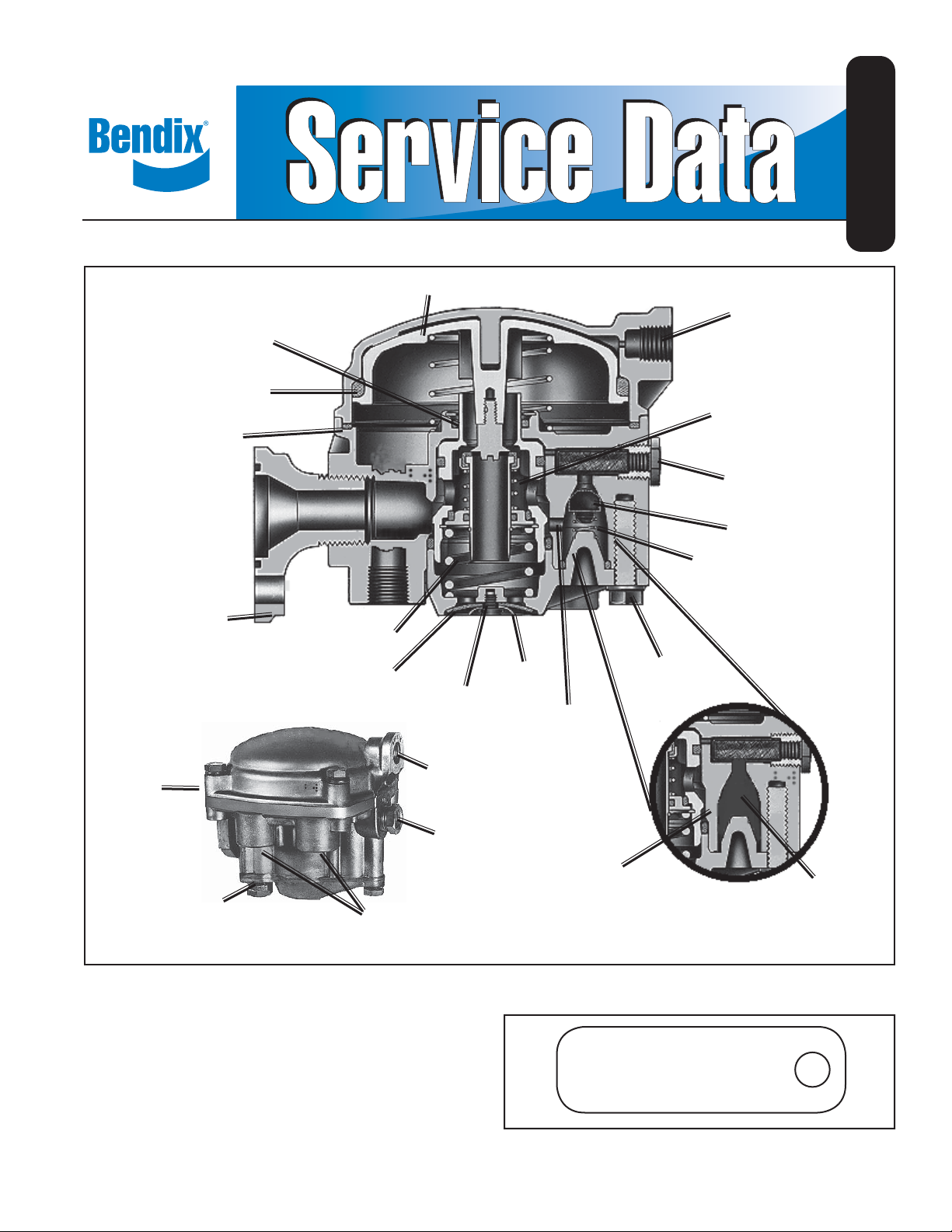
Bendix® RE-6™ and RE-6NC™ Relay Valves
RELAY PISTON
EMERGENCY
PISTON
SD-03-1151
SERVICE
PORT
O-RING
SEALING
RING
™
RE-6
Valve
MOUNTING
FLANGE
RE-6™ & RE-6NC™
Valves
RESERVOIR
PORT (2)
™
RE-6NC
ID TAG ATTACHED
SEE (FIGURE 2)
VALVE
SPRING
DIAPHRAGM
DELIVERY PORTS
(4)
SCREW
SERVICE
PORT
EMERGENCY
PORT
WASHER
CHECK VALVE
DELIVERY
PASSAGE
CHECK VALVE
DELIVERY
PASSAGE NOT
PRESENT
CAP
SCREW
INLET AND
EXHAUST
VALVE
EMERGENCY
SUPPLY PORT
CHECK VALVE
SPRING
RE-6NC
Valve
™
CHECK
VALVE
NOT
PRESENT
FIGURE 1 RE-6™ & RE-6NC™ RELAY VALVES
RE-6™ VALVE DESCRIPTION
The RE-6™ valve is used in dolly and trailer brake systems.
It is a dual function valve, combining the functions of a relay
valve and an emergency valve.
The relay function is identical to that of a relay valve, a
remotely controlled brake valve. Control pressure from the
towing vehicle is routed through the trailer service line and
RE-6NC SPECIAL
XXXXXX
SVC. REPL. XXXXXX
FIGURE 2 RE-6NC™ RELAY VALVE SPECIAL
IDENTIFICATION TAG
1
Page 2
CONTROL LINE
Service Brake Chamber
Slack Adjuster
Trailer Gladhand
FRONT
SUPPLY LINE
R-12P
Valve
™
Single Check
Valve
Reservoir
Bulkhead
™
SV-4
Valve
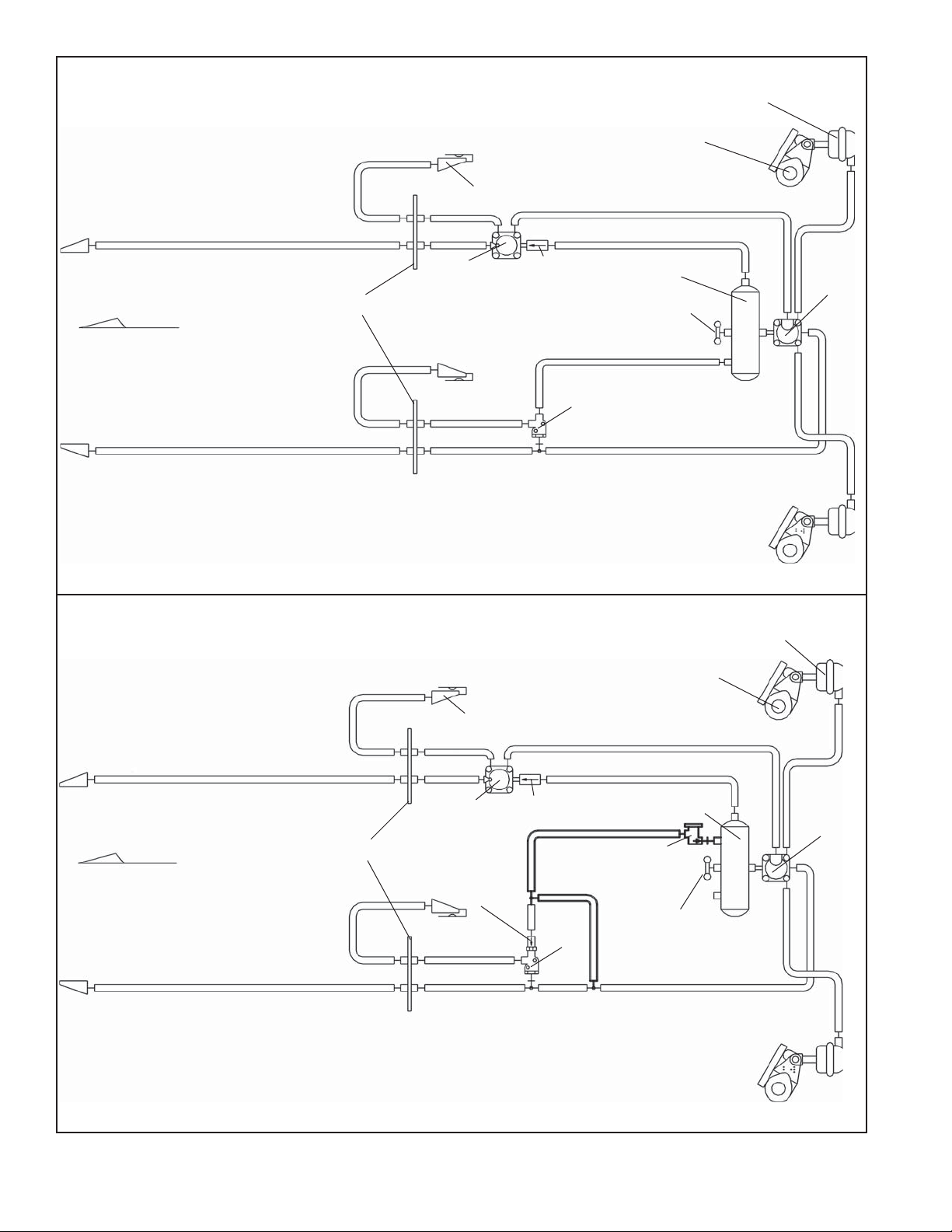
RE-6™ RELAY VALVE DOLLY SYSTEM CONFIGURATION
Trailer Gladhand
Drain
Valve
Service Brake Chamber
Slack Adjuster
RE-6
Valve
™
CONTROL LINE
™
R-12P
Valve
FRONT
Bulkhead
Single Check
Valve
SUPPLY LINE
RE-6NC™ RELAY VALVE DOLLY SYSTEM CONFIGURATION
FIGURE 3 - RE-6™ & RE-6NC™ RELAY VALVES SYSTEM CONFIGURATION
2
Single Check
Valve
™
SV-4
Valve
Reservoir
™
PR-3
Valve
Drain
Valve
™
RE-6NC
Valve
Page 3
on to the relay portion of the valve. The emergency function
of the valve automatically applies full trailer reservoir air
pressure to the trailer chambers when the trailer supply
pressure falls below a predetermined minimum value.
™
The RE-6
/RE-6NC™ relay emergency valve may be
fl ange or reservoir mounted. Ports are clearly identifi ed for
delivery, service, emergency (supply) and reservoir lines.
RE-6NC™ VALVE DESCRIPTION
The RE-6NC™ valve is a special non-charging relay
emergency valve. It is used on dollies to comply with
FMVSS 121. The RE-6NC™ valve eliminates the need for
a protected reservoir to provide the release air for the trailer
spring brakes when the following requirements are met:
- The trailer supply line must be 70 psi minimum with any
leakage-type service system failure.
- The parking brake must not drag at trailer supply line
pressures above 70 psi.
The relay function of the RE-6NC™ valve is identical to that
of the RE-6™ valve, serving the dolly or trailer system as
a remote controlled brake valve. The emergency function
of the valve automatically applies full trailer reservoir air
pressure to the trailer or dolly chambers when the trailer
supply pressure falls below a predetermined minimum
value. The major difference between the RE-6™ and the
RE-6NC™ valve is that the RE-6NC™ valve allows supply
pressure (initial charge) to release the spring brakes before
the dolly or trailer reservoir(s) is fi lled.
RE-6™ & RE-6NC™ VALVE SYSTEM
CONFIGURATION
In the RE-6™ valve dolly system, the supply air fl ows to the RE-
6™ valve, passes through the valve, holding the chambers in
the apply position while simultaneously fi lling the reservoir.
In the RE-6NC
supplied through the RE-6NC
valve system. The supply air fl ows to the RE-6NC™ valve,
acts upon the emergency piston, pushing the emergency
piston toward the inlet / exhaust valve seat. System
pressure in the chambers and reservoir are still at 0 psi in the
RE-6NC
™
In the RE-6NC
PR-3™ valve, which will allow the air to fl ow on to the
reservoir at a pressure setting of about 70 psi. The major
difference between the RE-6™ valve and the RE-6NC™
valve is that the RE-6NC™ valve does not require the
system to charge the reservoir to a predetermined psi
before drive away is allowed. Refer to Figure 3.
™
valve dolly system, reservoir air is not
™
valve, as it is in the RE-6™
valve system, allowing for faster trailer pull-away .
™
valve system, air is also fl owing to the
EMERGENCY
SUPPLY
RESERVOIR
45 PSI
CHAMBERS
45 PSI
45 PSI
RE-6™ Relay Valves
45 PSI
0 PSI
0 PSI
RE-6NC
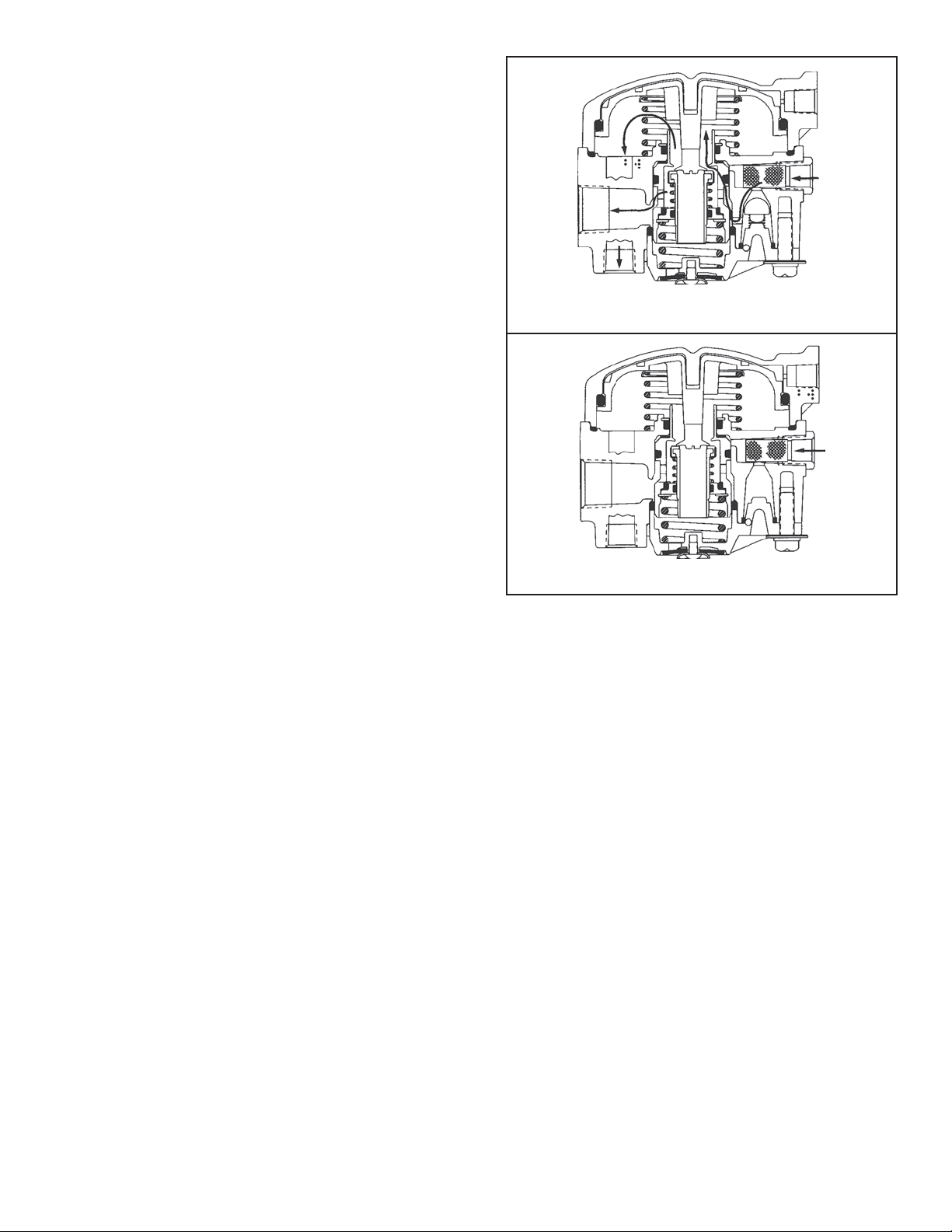
FIGURE 4 RE-6
BELOW 45 PSI
CHARGING THE RE-6™ & RE-6NC™ VALVES
BELOW 45 PSI
When the air brake system is charging below 45 psi,
emergency supply air enters the RE-6™ and RE-6NC™
valves emergency port. In the RE-6™ valve the air acts on
the check valve and the emergency piston. In the RE-6NC™
valve the air acts on the emergency piston, because there
is no check valve present. This allows for faster drive away
(reference FMVSS 121 regulation). In the RE-6™ valve, the
supply air is forced past the check valve, fl owing through
the emergency piston shoulder and past the inlet / exhaust
valve. The air fl ows to the upper portion of the valve,
underneath the relay piston and out to the service brake
chambers while simultaneously fi lling the reservoir with the
same air that is passing through the emergency piston. In the
RE-6NC™ valve, air is only acting upon the emergency
piston. The check valve is not present. In replacement
of the check valve, the RE-6NC™ valve uses a reservoir
control valve (the Bendix® PR-3™ valve), to allow the
reservoir to be fi lled. The PR-3™ valve is totally separate
from the RE-6NC™ valve, but is necessary for proper
operation of the RE-6NC™ valve. Air acts on the PR-3™
valve piston, but will not fl ow on to the reservoir until about
70 psi. Refer to Figure 4.
™
& RE-6NC™ RELAY VALVES CHARGING
™
Relay Valves
3
Page 4
RESERVOIR
45<>60 PSI
EMERGENCY
SUPPLY
45<>60 PSI
RESERVOIR
60 PSI
EMERGENCY
SUPPLY
60 PSI
45<>60 PSI
CHAMBERS
HOLDING
RE-6™ Relay Valve
45<>60 PSI
0 PSI
0 PSI
RE-6NC™ Relay Valve
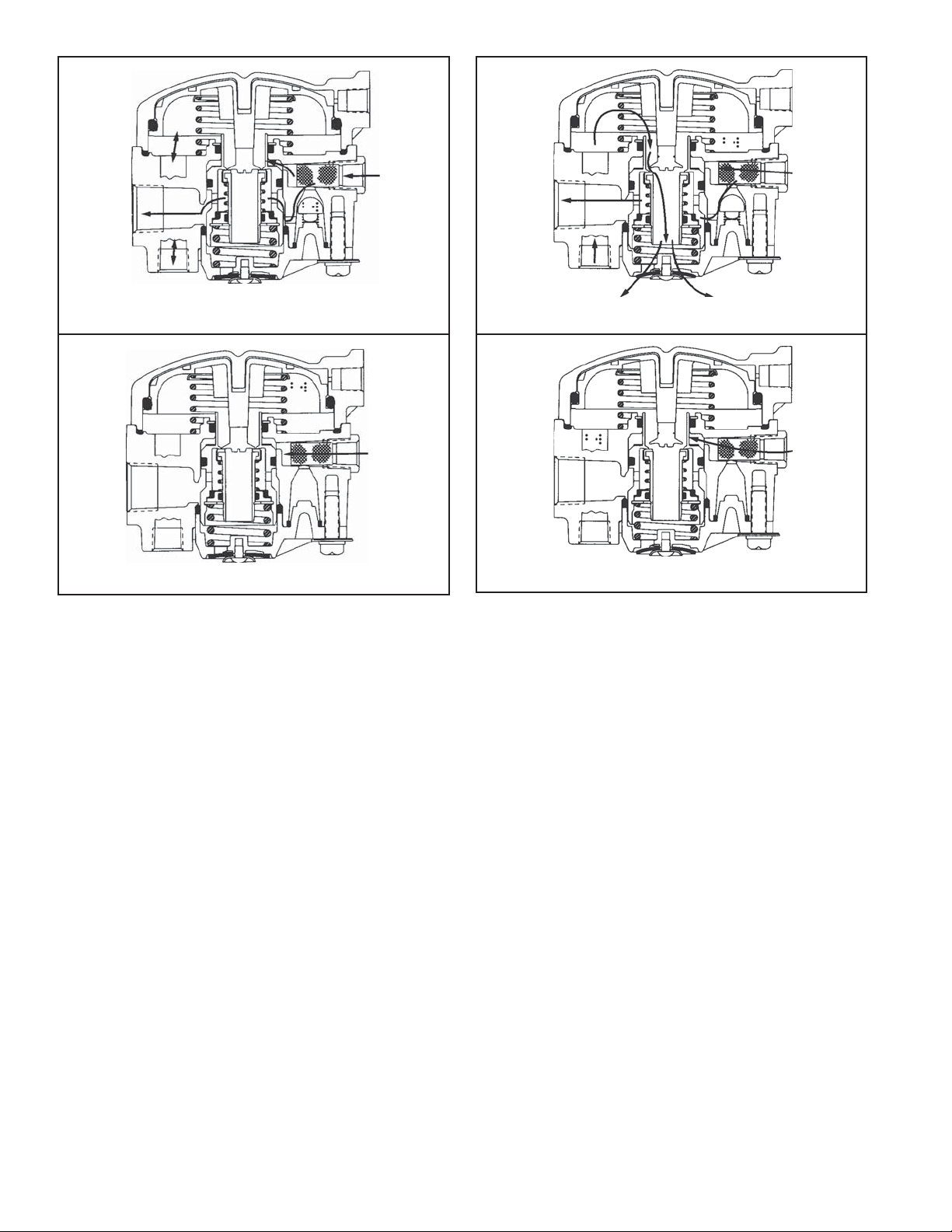
FIGURE 5 RE-6™ & RE-6NC™ RELAY VALVES CHARGING
HOLD POSITION
RE-6™ & RE-6NC™ VALVES CHARGING HOLD
POSITION
In the RE-6™ valve, as pressure increases in the reservoir,
the emergency piston is being pushed toward the seat on
the inlet and exhaust valve. When the emergency piston
reaches the seat of the inlet / exhaust valve, air is trapped
between the new seal and the chambers, holding the
chambers in the apply position. The check valve in the
RE-6™ valve will continue to remain open, charging
the reservoir. In the RE-6NC™ valve, air is acts on the
emergency piston, but there is still 0 psi in the reservoir
and the chambers. Air is also acting on the piston in the
PR-4™ valve, but still has not reached the opening pressure
of 70 psi. Refer to Figure 5.
CHARGING THE RE-6™ & RE-6NC™ VALVES
ABOVE 60 PSI
In the RE-6™ valve, as pressure increase beyond 60 psi, the
emergency piston and the inlet / exhaust valve, move from
the seat of the primary piston, opening the exhaust valve to
atmosphere allowing the service chambers to be exhausted.
The air will fl ow from the service chambers, back through
the RE-6™ valve and out the exhaust of the RE-6™ valve,
CHAMBERS
0 PSI
RE-6™ Relay Valve
60 PSI
0 PSI
0 PSI
RE-6NC™ Relay Valve
FIGURE 6 RE-6™ & RE-6NC™ RELAY VALVES CHARGING
ABOVE 60 PSI
allowing drive away . In the RE-6NC™ valve, air is still acting
upon the emergency piston, but there is no pressure in the
reservoir and the chambers. The emergency piston and
inlet / exhaust valve have moved to the exhaust position,
opening the exhaust portion of the valve to atmosphere.
The PR-3™ valve remains closed until reaching 70 psi,
allowing air to fl ow to the reservoir. Refer to Figure 6.
CHARGING THE RE-6NC™ VALVE ABOVE 70 PSI
Once system pressure reaches 70 psi, the PR-3™
reservoir control valve will open charging the reservoir(s).
Simultaneously the emergency piston and inlet / exhaust
valve of the RE-6NC™ valve is kept away from the seat
of the primary piston (keeping the exhaust valve open to
atmosphere). This is the major difference between the
RE-6™ valve and the RE-6NC™ valve. The RE-6NC™ valve
allows for quicker drive away , since the reservoir does not
need to be fi lled before the brakes are released. Refer to
Figure 7.
4
Page 5

RE-6™ & RE-6NC™ VALVES SERVICE
APPLICATION
During normal, service braking operation, the valve serves
as a relay valve, synchronizes tractor service (application)
SERVICE
HOLD
5 PSI
EMERGENCY
RESERVOIR
70 PSI
SUPPLY
70 PSI
RE-6NC™ Relay Valve
FIGURE 7 RE-6NC
PSI
air pressure with trailer service (application) air pressure
as the service foot brake valve on the tractor is operated.
If the tractor is equipped with a trailer hand (TC) valve, the
trailer brakes can be applied independently of the tractor
™
RELAY VALVE CHARGING ABOVE 70
SERVICE
BRAKE
APPLICATION
10 PSI
CHAMBER
HOLD 5 PSI
FIGURE 9 RE-6
HOLD
™
& RE-6NC™ RELAY VALVES SERVICE
NO AIR FLOW
enough to allow the inlet / exhaust valve to re-seat on the
emergency piston and close the inlet / exhaust valve. Air
is trapped between the seal of the emergency piston and
inlet / exhaust valve and the service chambers, making the
service brake application. The entrapment of air constitutes
the holding position of the valve. At this time, no air is
fl owing through the valve. Refer to Figure 9.
CHAMBER
APPLICATION
10 PSI
FIGURE 8 RE-6™ & RE-6NC™ RELAY VALVES SERVICE
APPLICATION
brakes. Air is applied to the control port of the RE-6™ and
RE-6NC™ valves, acting on the primary piston and moving
the inlet / exhaust valve away from the seat on the
emergency piston. Service application allows air to fl ow
from the reservoir, past the shoulder (on the emergency
piston) to the underside of the relay piston and on to the
service chambers to apply the brakes. Refer to Figure 8.
RE-6™ & RE-6NC™ VALVES SERVICE HOLD
Air is still being applied to the control port of the RE-6™
and RE-6NC™ valves, but the relay piston has moved
0 PSI
FIGURE 10 RE-6™ & RE-6NC™ RELAY VALVES SERVICE
EXHAUST
RE-6™ & RE-6NC™ VALVES SERVICE EXHAUST
When air is removed from the control port of the RE-6™ and
RE-6NC™ valves, the relay piston moves upward. As the
air is let off the control port, the relay piston moves from
its seat on the inlet / exhaust valve, opening the exhaust
path to atmosphere. Air fl ows from the service chambers,
past the relay piston, through the emergency piston and
inlet / exhaust valve to atmosphere past the diaphragm.
Refer to Figure 10.
5
Page 6

RE-6™ & RE-6NC™ VALVES EMERGENCY
APPLICATION
(Trailer air system charged to normal operating pressure).
Venting the emergency supply line to atmosphere will
cause the emergency portion of the relay emergency
valve to apply full trailer reservoir pressure to the trailer
service chambers. If the emergency supply line pressure
is reduced to approximately 20 psi, a graduated trailer
air chamber application will occur. The rate of this brake
application will depend upon the rate of pressure loss in
the emergency supply line.
TO RELEASE AN EMERGENCY APPLICATION
™
RE-6
Charge the trailer air system or:
A. For trailers equipped with standard brake chambers,
B. For trailers equipped with spring brake chambers,
& RE-6NC™ VALVES
block wheels and drain trailer reservoir.
block wheels and mechanically release spring brake
chambers via the mechanical release mechanism (for
specifi c instructions, refer to manufacturers service
literature.)
In an emergency , air would be removed from the emergency
™
supply line port of the RE-6
and RE-6NC™ valves, allowing
the emergency piston to return to its released position.
EMERGENCY
FALLING
FROM FULL
SYSTEM
PRESSURE
FULL SYSTEM
PRESSURE
FIGURE 11 RE-6
APPLICATION
™
& RE-6NC™ RELAY VALVE EMERGENCY
SUPPLY LINE
When the emergency piston moves back to its released
position, the seal is open between the emergency piston
and the inlet / exhaust valve. The open valve allows air to
fl ow from the reservoir, past the shoulder in the emergency
piston, past the inlet / exhaust valve, past the underside
of the relay piston moving on to the service chambers
creating an emergency application. Full reservoir pressure
will be applied to the service chambers and will not be
removed until the pressure in the emergency port of the
RE-6™ or RE-6NC™ valve reaches at least 60 psi. When
the emergency port pressure reaches any pressure above
60 psi, the emergency piston and inlet / exhaust valve will
move from the seat of the relay piston allowing the service
chambers to exhaust the air. Refer to Figure 11.
If the dolly is not equipped with parking actuators (such as
spring brakes), the wheels should be blocked to prevent
trailer movement.
WARNING! PLEASE READ AND FOLLOW
THESE INSTRUCTIONS TO A VOID PERSONAL
INJURY OR DEATH:
When working on or around a vehicle, the following
general precautions should be observed at all times.
1. Park the vehicle on a level surface, apply the
parking brakes, and always block the wheels.
Always wear safety glasses.
2. Stop the engine and remove ignition key when
working under or around the vehicle. When
working in the engine compartment, the engine
should be shut off and the ignition key should be
removed. Where circumstances require that the
engine be in operation, EXTREME CAUTION should
be used to prevent personal injury resulting from
contact with moving, rotating, leaking, heated or
electrically charged components.
3. Do not attempt to install, remove, disassemble
or assemble a component until you have read
and thoroughly understand the recommended
procedures. Use only the proper tools and observe
all precautions pertaining to use of those tools.
4. If the work is being performed on the vehicle’s
air brake system, or any auxiliary pressurized air
systems, make certain to drain the air pressure
from all reservoirs before beginning ANY work
on the vehicle. If the vehicle is equipped with an
®
AD-IS
be sure to drain the purge reservoir.
5. Following the vehicle manufacturer’s recommended
procedures, deactivate the electrical system in a
manner that safely removes all electrical power
from the vehicle.
6. Never exceed manufacturer’s recommended
pressures.
7. Never connect or disconnect a hose or line
containing pressure; it may whip. Never remove
a component or plug unless you are certain all
system pressure has been depleted.
air dryer system or a dryer reservoir module,
6
Page 7

8. Use only genuine Bendix® replacement parts,
components and kits. Replacement hardware,
tubing, hose, fi ttings, etc. must be of equivalent
size, type and strength as original equipment and
be designed specifi cally for such applications and
systems.
9. Components with stripped threads or damaged
parts should be replaced rather than repaired. Do
not attempt repairs requiring machining or welding
unless specifi cally stated and approved by the
vehicle and component manufacturer.
10. Prior to returning the vehicle to service, make
certain all components and systems are restored
to their proper operating condition.
11. For vehicles with Antilock Traction Control (ATC),
the ATC function must be disabled (ATC indicator
lamp should be ON) prior to performing any vehicle
maintenance where one or more wheels on a drive
axle are lifted off the ground and moving.
PREVENTIVE MAINTENANCE
Important: Review the Bendix Warranty Policy before
performing any intrusive maintenance procedures. A
warranty may be voided if intrusive maintenance is
performed during the warranty period.
No two vehicles operate under identical conditions, as a
result, maintenance intervals may vary. Experience is a
valuable guide in determining the best maintenance interval
for air brake system components. At a minimum, the valve
should be inspected every 6 months or 1500 operating
hours, whichever comes fi rst, for proper operation. Should
the valve not meet the elements of the operational tests
noted in this document, further investigation and service
of the valve may be required.
SERVICE CHECKS
1. Remove any accumulated contaminants. Visually
inspect the valve's exterior for excessive corrosion
or physical damage. Repair/replace the valve as
necessary.
2. Inspect all air lines connected to the valve for signs
of wear or physical damage. Repair/replace as
necessary.
3. Test air line fi ttings for excessive leakage and tighten
or replace as necessary.
OPERATIONAL AND LEAKAGE TESTS
1. Block the vehicle's wheels and fully charge the air
system.
2. Apply and release the service brakes several times
and check for prompt response of the brakes at all
appropriate wheels.
3. With the air system fully charged, apply a soap solution
to the RE-6™ or RE-6NC™ valve’s exhaust port.
Leakage of a 1" bubble in 5 seconds is permissible.
4. Make and hold a full brake application and again
apply a leak check solution to the RE-6
valve’s exhaust. Leakage of a 1" bubble in 3 seconds
is permissible.
5. With the brakes still applied, apply a leak check solution
around the valve where the cover meets the body . No
leakage at this point is permitted.
If the valve does not function as described; or if leakage is
excessive, repair the valve or replace it at any authorized
parts outlet.
™
or RE-6NC™
REMOVAL
1. Identify, mark or label all air lines and their connections
to the RE-6™ or RE-6NC™ valve. Scribe a line across
the body of the valve, including the valve cover.
When the assembly process is reached, the line will
serve as a reference to the position of the valve cover
on the valve body. Disconnect the air lines.
2. Remove the RE-6™ or RE-6NC™ valve from the
vehicle.
INSTALLATION
1. Use the mounting bracket provided with the valve, or,
if securing the valve to a reservoir, use a Schedule 80
(heavy wall) short couple, pipe nipple.
2. Reconnect all air lines to the valve using the identifi cation
made during removal.
3. Test all air fi ttings for excessive leakage and tighten
as needed. Also, perform OPERATIONAL AND
LEAKAGE TESTS before placing the vehicle back into
service.
DISASSEMBLY
The following procedure is for reference only. Always
have the appropriate maintenance kit on hand, and use its
instructions in lieu of those presented here. Refer to Figure
12 throughout. CAUTION: The RE-6™ & RE-6NC™ valve
may be lightly clamped in a bench vise during disassembly .
However, over-clamping will cause damage to the valve
and result in leakage and/or malfunction. If a vise is used,
position the valve so the jaws bear on the supply ports on
opposing sides of the valve's body.
1. Remove the four screws that secure the cover to the
body, set aside, and then slowly remove the cover.
2. Remove and discard the sealing ring(6) from sealing
ring grove located at the top of the valve body.
3. If a spring(5) is present (positioned between the bottom
side of the relay piston and the upper portion of the
valve body) set aside for the assembly process.
4. Remove the relay piston(3) from the valve body. It may
be necessary to tap the valve body lightly in order to
dislodge the relay piston from the valve cover.
5. Remove and discard the large o-ring(2) on the relay
piston.
6. Remove and discard the exhaust valve seat(4) from
the relay piston.
7
Page 8

7. Remove and discard o-ring(7) from under the crimpedon retaining ring located in the upper portion of the valve
body.
8. Turn the valve over, holding the exhaust cover , remove
the 3 cap screws(27) from the exhaust cover(22).
Remove the spring(20) and set the cap screws and
spring aside for the assembly process.
9. Remove and discard the small o-ring(19) from the
exhaust cover (located on the check valve post).
™
10. The RE-6NC
valve will not have a check valve(17)
and spring(18).
11. Remove and discard the check valve (17) and spring(18)
in the RE-6™ valve.
12. Remove and discard the diaphragm(23) from the
exhaust cover. Set screw(25) and washer(24) aside
for the assembly process.
13. Remove the emergency piston(9) and inlet / exhaust
valve(10) assembly by pushing the assembly through
the valve body , from the relay piston side of the valve.
The whole assembly will come out of the valve body
as one unit.
14. Remove and discard o-ring(8) located in the grove of
the emergency piston.
15. Remove and discard o-ring(21), which creates the
seal between the emergency piston and the exhaust
cover.
16. Remove valve retainer(16) with appropriate pliers and
set aside for the assembly process.
17. Remove and discard all internal parts. Valve guide(15),
o-rings(13&14), spring(12), valve retainer(11), inlet /
exhaust valve(10).
CLEANING & INSPECTION
1. Using mineral spirits or an equivalent solvent, clean and
thoroughly dry all metal parts. Do not damage bores
with metal tools.
2. Wash all non-metallic components in a soap and water
solution. Dry thoroughly.
3. Inspect interior and exterior of all metal parts for severe
corrosion, pitting, and cracks. Superfi cial corrosion
and/or pitting on the exterior of the body and cover is
acceptable. Replace the entire valve if the body or
cover interior show signs of corrosion or pitting.
4. Inspect each non-metallic component for cracks, wear,
or distortion. Replace the valve if these conditions are
found.
5. Make certain the air channel running from the cover
through the top surface of the body to the supply port
is clear and free of obstruction.
6. Inspect the pipe threads in the body. Make certain they
are clean and free of thread sealant.
7. Inspect all air line fi ttings for corrosion. Replace as
necessary. Remove all old thread sealant before
reuse.
8
ASSEMBLY
Before assembly , lubricate all o-rings, seals, and pistons as
well as body and cover bores, using the lubricant provided
in the maintenance kit. Use all of the lubricant, and spread
it evenly on the rubbing surfaces.
1. Install o-ring(8) into the grove on the emergency
piston(9).
2. Install the inlet / exhaust valve assembly into the
emergency piston. Packaged as 1 unit.
3. With Tru-Arc pliers, install valve retainer(16), making
certain it is in the grove in the emergency piston.
4. Install the emergency piston(9) (including the inlet /
exhaust valve assembly just installed) into the valve
body.
5. Install the spring(20) in body.
6. Install o-ring(19) on to the check valve post, located on
the exhaust cover.
7. Install the diaphragm(23) on to the exhaust cover,
securing it with the screw(25) and washer(24) set aside
in the disassembly process.
™
8. For the RE-6
spring(18) on to the check valve(17) and drop into the
check valve cavity . The spring will fi t in groove on the
exhaust cover (making sure spring is positioned in the
center of the cavity). If changing the RE-6NC™ valve,
discard the check valve(17) and spring(18).
9. Install o-ring(21) into channel between the valve body
and emergency piston.
10. Turn the valve over and install o-ring(7) in the channel
under the crimped-on retaining ring located in the upper
portion of the valve body. (This must be done before
the exhaust cover is installed because the emergency
piston will cover this o-ring).
11. Turn the valve back over and install the exhaust
cover(22). Install cap screws and lock washers, torque
to approximately 100 inch pounds.
12. Turn the valve over and install the sealing ring(6) in
the grove located at the top of the valve body.
13. Apply the adhesive sealant to the seat(4) threads and
install in to the relay piston.
14. Install the o-ring(2) around the relay piston(3).
15. Insert the relay piston(3) into the valve cover(1) and
push the piston to the top of the cover.
16. If so equipped, install the piston return spring(5).
17. Install the cover to body, making certain the scribe
marks line up marked in the "REMOVAL" section.
18. T orque the cap screws to approximately 100 inch
pounds.
19. Perform OPERA TIONAL AND LEAKAGE TESTS before
returning the vehicle to service.
valve, install the small check valve
Page 9

O-RING (2)
O-RING (7)
BODY
COVER (1)
O-RING (8)
EMERGENCY
PISTON (9)
INLET & EXHAUST
VALVE (10)
RELAY PISTON (3)
SPRING (5)
SEALING RING (6)
A
SEAT (4)
VALVE RETAINER (11)
SPRING (12)
O-RING (13)
O-RING (14)
VALVE GUIDE (15)
VALVE RETAINER (16)
CHECK VALVE (17)
SPRING (18)
O-RING (19)
CHECK VALVE
POST
EXHAUST
COVER (22)
DIAPHRAGM (23)
WASHER (24)
INLET
EXHAUST
VALVE
ASSEMBLY
SEE NOTE 1
SPRING (20)
O-RING (21)
LOCKWASHER
(26)
CAP SCREW
SCREW (25)
FIGURE 12 EXPLODED VIEW
Note 1: The OE production valve does not have this valve retainer. The maintenance kit includes the retaining ring to hold together
the inlet/exhaust valve. The inlet/exhaust valve comes as one piece in the maintenance kit.
(27)
9
Page 10

OPERATION
Air fl ow in the normal direction moves the check valve
from its seat, and the fl ow is unobstructed. Flow in the
reverse direction is prevented by the seating of the ball or
wafer-type disc, which is caused by a drop in up-stream
air pressure and assisted by the spring.
PREVENTATIVE MAINTENANCE
Every six months, 1,800 operating hours or every 50,000
miles inspect all parts.
Replace any check valves leaking or showing signs of wear
or deterioration. Check for proper operation.
OPERATION & LEAKAGE CHECKS
NOTE: Depending upon installation, it may be easier or
necessary to completely remove check valves so that the
following checks may be made.
With air pressure present at outlet side of check valve and
the inlet side open to atmosphere, coat the open end of
the check valve with soap suds; a 1" bubble in 5 seconds
is permissible.
If the check valve does not function as described, or
leakage is excessive, it is recommended that it be replaced
with a new genuine Bendix part available at any Bendix
parts outlet.
REMOVAL
Block and hold vehicle by means other than air brakes.
Completely drain all reservoirs.
Disconnect air lines at single check valve and remove.
DISASSEMBLY/ASSEMBLY
Note: There are no Disassembly/Assembly procedures for
SC-3™ valves. They are non-serviceable items. If a valve
does not meet the Operational and Leakage tests, it should
be replaced at any authorized Bendix parts outlet.
TESTING AND TROUBLESHOOTING
Perform “Operating and Leakage Checks”.
10
Page 11

11
Page 12

12
BW1570 © 2007 Bendix Commercial Vehicle Systems LLC. All rights reserved. 7/2007 Printed in U.S.A.
 Loading...