

Page 1
®
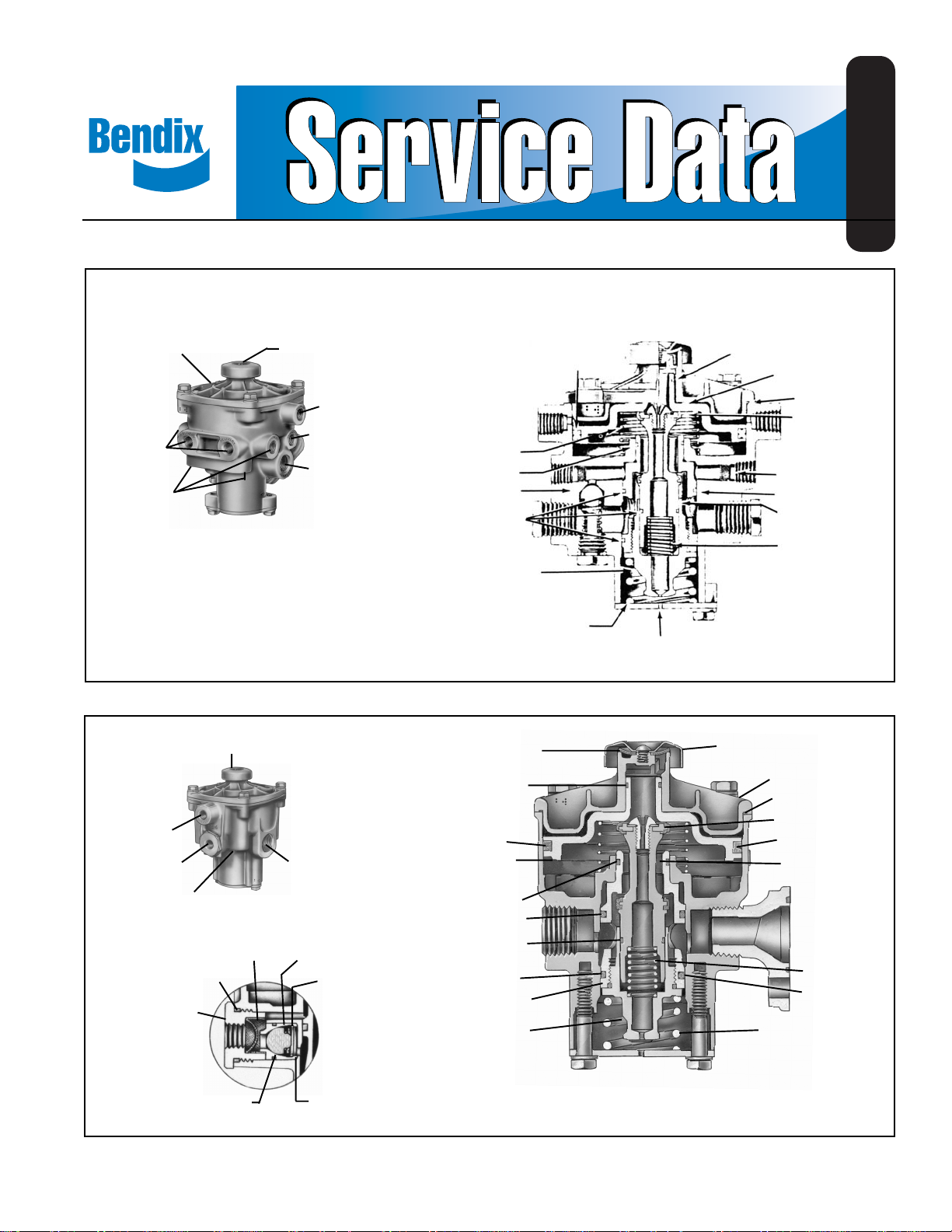
Bendix® RE-4™ Relay Emergency Valve
SD-03-1150
COVER
DELIVERY
PORTS (3)
DELIVERY
PORTS (3)
FIGURE 1 - RE-4
SERVICE
PORT
EMERGENCY
PORT
DELIVERY
PORTS (4)
CAP NUT
(20)
EXHAUST COVER
SERVICE
PORTS
EMERGENCY
PORTS (2)
RESERVOIR
PORTS
™
RELAY EMERGENCY VALVE (OLD STYLE)
EXHAUST
FILTER
PISTON TURN
RESERVOIR
PORTS (2)
O-RING
(22)
FILTER
(21)
CHECK
VALVE (24)
CHECK VALVE
SPRING (25)
SPRING
O-RING
CHECK VALVE
O-RINGS
EMERGENCY
PISTON CAP
NUT
EXHAUST
DIAPHRAGM (17)
O-RING (19)
SPRING (15)
O-RING (4)
O-RING (3)
O-RING (12)
O-RING (2)
EMERGENCY
PISTON (5)
EMERGENCY
PISTON CAP
NUT (6)
QUAD
RING
SPRING
O-RING
RELAY PISTON
GROMMET
EXHAUST
VALVE
EMERGENCY LINE
FILTERS (2)
EMERGENCY
PISTON
INLET VALVE
SPRING
COVER PLATE VENT
EXHAUST COVER (16)
TOP COVER (11)
O-RING (13)
EXHAUST VALVE (9)
RELAY PISTON (14)
INLET VALVE
BODY (10)
VALVE
SPRING (7)
O-RING (8)
EMERGENCY
SPRING (1)
CHECK VALVE
FIGURE 2 - RE-4
O-RING
SEAT (23)
™
RELAY EMERGENCY VALVE
(26)
1
Page 2

DESCRIPTION
The relay emergency valve is normally used in trailer braking
systems. It is a dual function valve, combining the functions
of a relay valve and an emergency valve.
RESERVOIR
SERVICE LINE
EMERGENCY LINE
FIGURE 3 - TYPICAL RELAY-EMERGENCY VALVE
TRAILER PIPING
The relay function is identical to that of a relay valve, serving
the trailer air brake system as a remote controlled brake
valve. Control (service) pressure from the towing vehicle is
routed through the trailer service line and on to the relay
portion of the valve.
The emergency function of the valve automatically applies
full trailer reservoir air pressure to the trailer chambers
when the trailer supply pressure falls below a predetermined
minimum.
For ease of service the valve features an “insert” cartridge
consisting of the inlet/exhaust valve and emergency piston.
Removal of the insert can usually be accomplished without
line removal.
The valve may be flange or reservoir mounted, and identified,
convenient porting locations of delivery, service, emergency
(supply) and reservoir ports are provided. (Note: Reference
Figures 1 and 2, two configurations of the RE-4™ valve are
shown). The older configuration (Figure 1) contained a total
of 13 ports. Check valve access was via a pipe plug on the
bottom of the valve. The newer and current configuration
contains 8 ports and check valve access is via a side cap
nut Interior components of both valves are identical.
RELAY
EMERGENCY
VALVE
SLACK
ADJUSTER
DRAIN
COCK
BRAKE CHAMBER
charged. This application is continued until the trailer supply
(emergency) line is charged to 60-65 psi, at which time the
application is automatically released. The trailer reservoir
continues to be charged to full operating pressure.
SERVICE APPLICATION
During normal service braking operation, the valve serves as
a relay valve, synchronizing tractor service (application) air
pressure with trailer service (application) air pressure as the
service foot brake valve on the tractor is operated. If the
tractor is equipped with a trailer hand control (TC) valve, the
trailer brakes can also be applied independently of the tractor
brakes.
EMERGENCY APPLICATION
(TRAILER AIR SYSTEM CHARGED TO NORMAL
OPERATING PRESSURE)
Venting the trailer supply line to atmosphere will cause the
emergency portion of the relay emergency valve to apply full
trailer reservoir pressure to the trailer air chambers.
If the trailer supply line pressure is reduced to approximately
20 psi due to leakage or conditions other than above, a
graduated trailer air chamber application will occur. The rate
of this brake application will depend upon the rate of pressure
loss in the supply line.
If the trailer is not equipped with parking actuators (such as
spring brakes), the trailer wheels should be blocked to
prevent trailer movement in the event reservoir pressure
would be depleted.
TO RELEASE AN EMERGENCY APPLICATION
Recharge trailer air system or:
A. For trailers equipped with standard brake chambers,
block wheels and drain trailer reservoir.
B. For trailers equipped with spring brake chambers, block
wheels and mechanically release spring brake chambers
via the mechanical release mechanism. (For specific
instructions, refer to manufacturer’s service literature.)
PREVENTIVE MAINTENANCE
Important: Review the Bendix Warranty Policy before
performing any intrusive maintenance procedures. A warranty
may be voided if intrusive maintenance is performed during
the warranty period.
OPERATION
INITIAL CHARGING
When a tractor is connected to a trailer and the service and
emergency lines are opened (via the tractor protection
system), the valve permits charging the trailer reservoir to
approximately the same air pressure as that of the tractor
reservoir. Under initial charge conditions, the valve applies
trailer service air chambers as the trailer emergency line is
2
No two vehicles operate under identical conditions, as a
result, maintenance intervals may vary. Experience is a
valuable guide in determining the best maintenance interval
for air brake system components. At a minimum, the valve
should be inspected every 6 months or 1500 operating hours,
whichever comes first, for proper operation. Should the valve
not meet the elements of the operational tests noted in this
document, further investigation and service of the valve may
be required.
Page 3

OPERATING AND LEAKAGE TEST
REMOVING AND INSTALLING
Check tractor dash air gauge against a test gauge known to
be accurate prior to performing these tests. Connect tractor
air lines to the trailer on which this valve is to be tested.
Block wheels or otherwise hold both vehicles by a means
other than air brakes during these tests.
1. Start these tests with no air pressure in the tractor or
trailer air brake system. Open cut-out cocks, if installed,
and place tractor protection control valve in normal
position. As system pressure ascends and the trailer
emergency line is charged, note that the trailer brakes
are applied. Trailer brake application should completely
release as trailer emergency line pressure reaches
approximately 60-65 psi.
2. Fully charge tractor and trailer air brake systems. Make
several service brake application and check for prompt
braking response at all trailer wheels. With brakes
released and system reservoir pressure stabilized at
90-100 psi, with engine stopped, a two minute check
should result in no more than a six pound pressure drop
for the combination vehicle system. If this check indicates
possible excessive leakage of valve, soap suds should
be applied to cover plate, cover plate vent, and exhaust
port of valve to detect possible inlet valve, inlet valve guide
o-ring and emergency piston o-ring leakage. A combined
leakage as indicated by a 1” soap bubble in not less
than 5 seconds is permissible. No leakage is permissible
at pipe plugs or fittings.
3. Make and hold a full service brake application with system
reservoir pressure stabilized at 100-120 psi with engine
stopped. A two minute check should result in no more
than an eight (8) psi pressure drop for the combination
vehicle system. If this check indicates possible excessive
leakage of valve, soap suds should be applied to cover
plate, cover plate vent, and exhaust port to detect exhaust
valve, valve guide o-ring, emergency piston o-ring and
relay piston o-ring leakage. A combined leakage as
indicated by a 1” soap bubble in not less than 2 seconds
is permissible. Release the service brake application.
4. With tractor and trailer air brake system fully charged,
place the tractor protection control valve to “Emergency”
position or close the supply line cut-out cock on the
tractor and uncouple the trailer emergency line coupling.
Note that trailer brakes apply promptly. Check leakage
at valve, and at the emergency line coupling. Reconnect
and recharge tractor and trailer air brake system, noting
that trailer brakes release at a maximum of 65 psi trailer
emergency line pressure as the trailer air brake system
is recharged to full normal operating pressure.
5. With tractor and trailer air brake system fully charged,
stop engine. Reduce pressure by making a series of
applications and note that trailer brakes apply
automatically at approximately 40 psi tractor reservoir
pressure or at the automatic emergency setting of the
tractor protection equipment, if installed.
If the valve does not function as described, or leakage is
excessive, it is recommended that it be replaced with a new
or remanufactured unit or repaired with genuine Bendix parts
available at Bendix outlets.
REMOVING
1. Block trailer wheels.
2. Drain trailer systems air reservoirs.
3. Identify and disconnect air lines from valve. (Note: the
emergency piston and valve assembly, generally referred
to as the “insert” can be removed without line removal.
To remove the insert, remove cover plate and pull insert
out.)
4. Remove mounting bolts, then valve.
INSTALLING
If valve will be flange mounted directly to steel, it is
recommended that a flange gasket be utilized to prevent
electrolytic action between the unlike metals.
If the valve is adapter or nipple mounted directly to a reservoir,
it is recommended that “Never Seez” lubricant be applied to
the threads before installation. This will prevent galling of
the threads and make removal easier.
1. Clean and inspect all connecting lines and hoses for
cracks, deterioration or damage. Replace as necessary.
2. Mount valve securely.
3. Connect all lines and hoses to valve.
DISASSEMBLY
1. Remove capscrews, lockwasher, then cover plate and
emergency spring (1) from bottom of valve.
2. Remove insert (5) through bottom of valve (keep insert
centered during removal to avoid damage to exhaust
valve.
(Note: If new insert is to be installed omit steps 3-8).
3. Remove three o-rings (2) (3) & (4) from insert.
4. Using wrench flats provided, remove emergency piston
cap nut (6) from emergency piston (5). Use care to avoid
damaging finished diameters.
5. Remove valve spring (7) and emergency piston cap nut
o-ring (8).
6. Remove Phillips head screw, lockwasher and exhaust
valve (9) from inlet valve body (10).
7. Remove inlet body from emergency piston.
8. Remove inlet valve o-ring (12) from inlet valve body. Mark
cover and body to assure proper positioning when
assembling.
9. Remove capscrews, lockwashers then top cover (11) from
body. Remove o-ring (13) from cover.
10. Remove relay piston (14) and piston return spring (15)
from body.
11. Remove screw from exhaust cover (16) and remove
exhaust diaphragm (17).
12. Remove seal ring (18) and o-ring (19) from relay piston.
3
Page 4

13. Remove emergency-supply cap nut (20).
14. Remove filter (21) and o-ring (22) from cap nut.
15. Remove check valve seat (23), check valve (24), and
check valve spring (25). Remove o-ring (26).
CLEANING AND INSPECTION OF PARTS
Wash all metal parts in mineral spirits.
Wipe rubber parts dry.
Inspect all parts for wear, damage or deterioration.
Clean or replace all filters. Replace all rubber parts and any
other parts not considered serviceable by these inspections
with Genuine Bendix parts.
ASSEMBLY
NOTE: All torques specified are assembly torques and can
be expected to fall off after assembly. Do not
retorque after initial assembly torques fall. For
assembly, hand wrenches are recommended.
Prior to assembly, lubricate all o-rings and mating
surfaces with Dow-Corning 55-M pneumatic grease
(Bendix Pc. No. 291126).
1. Install o-ring (13) on top cover (11).
2. Install seal ring (18) and o-ring (19) on piston (14).
3. Install piston return spring (15) in body. Install relay piston
in cover; it should be a neat, sliding fit.
4. Install top cover/piston assembly. Torque cap screws to
100 inch pounds.
5. Install exhaust diaphragm (17), cover (16) and retaining
screw.
Note: If new insert is to be installed omit steps 6-12.
6. Install three o-rings (2) (3) & (4) on the emergency piston
insert and o-ring (12) on the inlet valve body (10).
7. Install valve spring (2) in inlet valve body (10) and slide
inlet valve body into the emergency piston cap nut (6).
Use care to avoid damaging the inlet valve o-ring.
8. Install emergency piston cap nut o-ring (8).
9. Install emergency piston cap nut in emergency piston
and tighten. Torque to 200-250 in. lbs.
10. Install exhaust valve (9) on inlet valve body using
lockwasher and Phillips head screw. (Bead on rubber
and recess in valve surface should face head of screw).
Torque to 80-120 in. lbs.
11. Install insert assembly in valve body.
12. Install emergency piston spring (1).
13. Install cover plate, lockwashers and cap nuts. Torque
cap nuts to approximately 100 in. lbs.
14. Install check valve (24) and check valve spring (25) in
check valve seat (23).
15. Install check valve o-ring (26) in body and install check
valve seat with check valve in body.
16. Install filter (21) and o-ring (22) on cap nut (20) and install
cap nut in body. Torque to 75-175 in. lbs.
17. Install plugs in unused ports.
18. Check valve as outlined in “Operating and Leakage
Check” sections before placing vehicle in service.
WARNING! PLEASE READ AND FOLLOW
THESE INSTRUCTIONS TO AVOID
PERSONAL INJURY OR DEATH:
When working on or around a vehicle, the following
general precautions should be observed at all times.
1. Park the vehicle on a level surface, apply the
parking brakes, and always block the wheels.
Always wear safety glasses.
2. Stop the engine and remove ignition key when
working under or around the vehicle. When
working in the engine compartment, the engine
should be shut off and the ignition key should be
removed. Where circumstances require that the
engine be in operation, EXTREME CAUTION should
be used to prevent personal injury resulting from
contact with moving, rotating, leaking, heated or
electrically charged components.
3. Do not attempt to install, remove, disassemble or
assemble a component until you have read and
thoroughly understand the recommended
procedures. Use only the proper tools and observe
all precautions pertaining to use of those tools.
4. If the work is being performed on the vehicle’s air
brake system, or any auxiliary pressurized air
systems, make certain to drain the air pressure from
all reservoirs before beginning ANY work on the
vehicle. If the vehicle is equipped with an AD-IS
air dryer system or a dryer reservoir module, be
sure to drain the purge reservoir.
5. Following the vehicle manufacturer’s
recommended procedures, deactivate the electrical
system in a manner that safely removes all
electrical power from the vehicle.
6. Never exceed manufacturer’s recommended
pressures.
7. Never connect or disconnect a hose or line
containing pressure; it may whip. Never remove a
component or plug unless you are certain all
system pressure has been depleted.
8. Use only genuine Bendix® replacement parts,
components and kits. Replacement hardware,
tubing, hose, fittings, etc. must be of equivalent
size, type and strength as original equipment and
be designed specifically for such applications and
systems.
9. Components with stripped threads or damaged
parts should be replaced rather than repaired. Do
not attempt repairs requiring machining or welding
unless specifically stated and approved by the
vehicle and component manufacturer.
10. Prior to returning the vehicle to service, make
certain all components and systems are restored
to their proper operating condition.
™
4
BW1433 © 2004 Bendix Commercial Vehicle Systems LLC. All rights reserved. 3/2004 Printed in U.S.A.
 Loading...