

Page 1
®
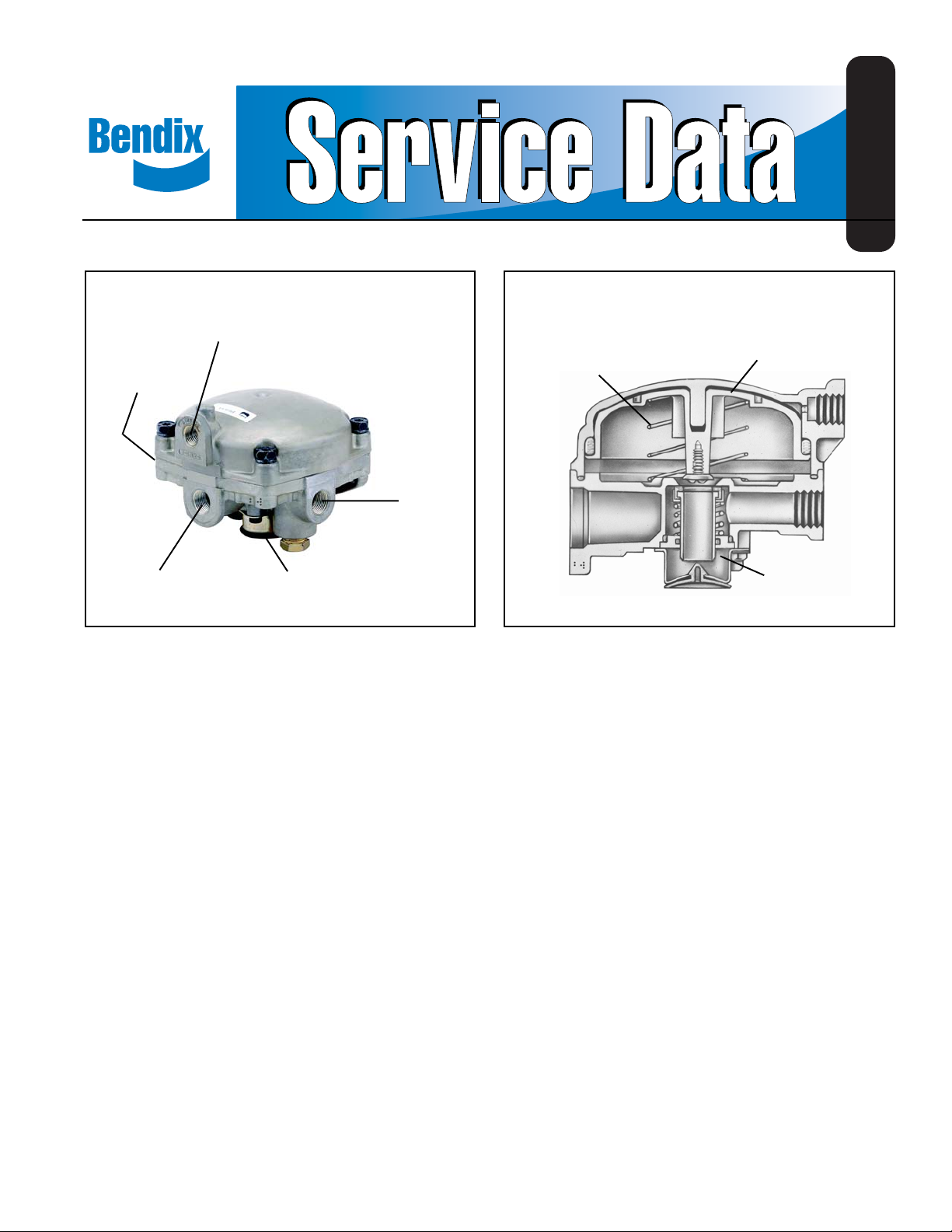
Bendix® R-6™ Relay Valve
SERVICE
PORT
SUPPLY PORT
(RESERVOIR
MOUNT TYPE)
DELIVERY
PORTS (4)
RETURN
SPRING
SD-03-1060
RELAY PISTON
SUPPLY
PORT
FIGURE 1
EXHAUST
DESCRIPTION
The relay valve in an air brake system functions as a relay
station to speed up the application and release of the brakes.
The valve is normally mounted at the rear of the vehicle in
proximity to the chamber it serves. The valve operates as a
remote controlled brake valve that delivers or releases air to
the chamber in response to the control air delivered to it
from the foot brake valve or other source. The R-6™ relay
valve is a piston operated valve. For ease of servicing, an
“insert” or “cartridge” type inlet/exhaust valve is employed.
This feature permits service of the inlet/exhaust valve without
line removal. The R-6™ relay valve may be mounted directly
to or remotely from the reservoir which provides its supply
pressure. Standard porting consist s of one (1) service port
and four (4) delivery ports. There are two (2) supply ports in
the reservoir mounted valve and one (1) supply port in the
remote mount valve.
™
R-6
RELAY
VALVE INSERT
FIGURE 2
OPERATION
APPLYING
Air pressure delivered to the service port enters the small
cavity above the piston and moves the piston down. The
exhaust seat moves down with the piston and seats on the
inner or exhaust portion of the inlet/exhaust valve, sealing
off the exhaust passage. At the same time, the outer or inlet
portion of the inlet/exhaust valve moves off its seat, permitting
supply air to flow from the reservoir, p ast the open inlet valve
and into the chambers.
BALANCED
The air pressure being delivered by the open inlet valve also
is effective on the bottom area of the relay piston. When air
pressure beneath the piston equals the service air pressure
above, the piston lifts slightly and the inlet spring returns
the inlet valve to its seat. The exhaust remains closed as
the service line pressure balances the delivery pressure.
(NOTE: Some valves are equipped with a piston return spring
which will assist the lifting of the piston). As delivered air
pressure is changed the valve reacts instantly to the change
holding the brake application at that level.
1
Page 2
RELEASING
When air pressure is released from the service port and air
pressure in the cavity above the relay piston is exhausted,
air pressure beneath piston lifts the relay piston and the
exhaust seat moves away from the exhaust valve, opening
the exhaust passage. With the exhaust passage open, the
air pressure in the chambers is then permitted to exhaust
through the exhaust port, releasing the brakes.
PREVENTIVE MAINTENANCE
Important: Review the Bendix Warranty Policy before
performing any intrusive maintenance procedures. A warranty
may be voided if intrusive maintenance is performed during
the warranty period.
No two vehicles operate under identical conditions, as a
result, maintenance intervals may vary. Experience is a
valuable guide in determining the best maintenance interval
for air brake system components. At a minimum, the valve
should be inspected every 6 months or 1500 operating hours,
whichever comes first, for proper operation. Should the valve
not meet the elements of the operational tests noted in this
document, further investigation and service of the valve may
be required.
4. Make and hold a brake valve application; coat the exhaust
port with soap solution and check for leakage; 1" bubble
in 3 seconds leakage permitted.
If leakage is detected, replacing the inlet/exhaust valve may
correct the problem. If leakage still occurs, leakage may be
caused by relay piston o-ring or exhaust valve seat.
5. Make and hold a brake valve application; coat outside of
valve body in area where cover joins the body for cover
o-ring leakage No leakage permitted. If the valve does
not function as described above, or if leakage is
excessive, it is recommended that the valve be replaced
with a new or remanufactured unit, or repaired with
genuine Bendix parts available at Bendix outlets.
REMOVING AND INSTALLING
REMOVING
Block and hold vehicle by means other than air brakes.
Drain air brake system reservoirs.
If entire valve is to be removed, identify air lines to facilitate
installation.
Disconnect air lines from valve*.
OPERATING AND LEAKAGE TEST
1. Fully charge air brake system and adjust brakes.
2. Make several brake applications and check for prompt
application and release at all appropriate wheels.
3. With brake valve in released position, coat the exhaust
port with soap solution and check for inlet valve and valve
guide o-ring leakage; 1" bubble in 5 seconds leakage
permitted.
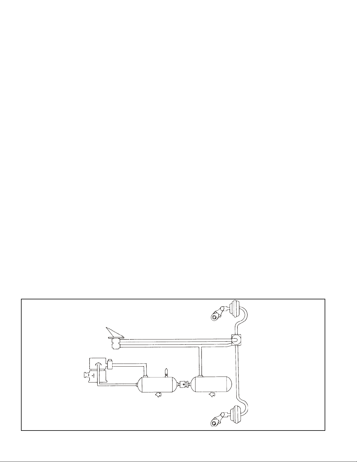
BRAKE
VALVE
COMPRESSOR GOVERNOR
SUPPLY
RESERVOIR
Remove mounting bolts, then valve.
*It is generally not necessary to remove entire valve to service
the inlet/exhaust valve. The inlet/exhaust valve insert can be
removed by removing the two exhaust cover cap screws
and cover. Insert then may be pulled out.
CAUTION: DRAIN RESERVOIRS BEFORE REMOVING
INSERT. Use care so as not to damage inlet/exhaust valve
or guide o-ring.
RELAY
VALVE
SERVICE
RESERVOIR
TYPICAL RELA Y V AL VE PIPING SINGLE CIRCUIT SYSTEM
2
BRAKE
CHAMBERS
Page 3

INSTALLING
Clean air lines connecting to valve.
Inspect all lines and/or hoses for damage and replace as
necessary.
Install valve and tighten mounting bolts.
Connect air lines to valve (Plug any unused ports).
T est valve as outlined in “Operating and Leakage Tests.”
DISASSEMBL Y
NOTE: Prior to disassembly , mark location of cover to body
to facilitate assembly.
1. Remove cover cap screws (1). Remove cover (2) with
relay piston (4) and spring (6) (if so equipped).
2. Remove relay piston (4) from cover.
3. Remove piston o-ring (3) from piston (4) and cover seal
o-ring from body .
4. Remove exhaust cover cap screws, (19) exhaust cover,
and remove inlet/exhaust valve insert (8) from body(7).
5. Remove exhaust seat (5) from relay piston (4) and
exhaust check valve(18). (Remove only if new parts are
to be installed).
INLET/EXHAUST V AL VE INSERT DISASSEMBL Y
NOTE: If complete inlet/exhaust valve is replaced, disregard
steps 6 to 9.
6. Depress and hold valve guide down against valve spring
tension and remove retainer (16).
7. Remove valve insert seal o-ring (13), valve guide (14),
spring (12), and valve retainer (1 1).
8. Remove the inlet/exhaust valve (9) from its body (10).
9. Remove inner o-ring (15) from valve guide (14).
CLEANING AND INSPECTION
Wash all metal parts in mineral spirits; wipe all rubber parts
dry . Inspect all parts for signs of wear and/or deterioration.
Inspect springs for cracks, distortion or corrosion.
Inspect inlet seat and exhaust seat for nicks and burrs and
replace as necessary. It is recommended that all rubber
parts be replaced, and that any part showing signs of wear
or deterioration be replaced.
ASSEMBL Y
NOTE: All torques specified in this manual are assembly
torques and can be expected to fall off after
assembly. Do not retorque after initial assembly
torques fall. (For assembly, hand wrenches are
recommended)
1. Prior to assembly, lightly lubricate the relay piston guide
post, o-rings, cover bore and inlet body with Dow Corning
Silicone 55-M Pneumatic grease (Bendix Pc. No.
291 126).
INLET/EXHAUST V AL VE ASSEMBL Y
NOTE: If new inlet/exhaust valve assembly insert is used,
disregard Step s 2 to 6.
2. Install inlet/exhaust valve (9) over valve body (10), smooth
surface up.
3. Position valve retainer (11) over inlet valve body (10) and
valve.
4. Install inlet valve spring (12) over inlet body (10) and install
o-ring (15) in the inner groove in the valve guide (14).
5. Depress and hold guide down against inlet spring and
install retainer ring (16) (A 9/16" twelve point socket can
be used to push the retainer ring down until it snaps in
the groove in the inlet valve body).
6. Install valve insert seat o-ring (13).
COMPLETE V ALVE ASSEMBL Y
7. Install insert (8) in valve body (7), install exhaust cover
(17) and secure with 10-24 screws (19) torque to
approximately 20-30 inch pounds.
8. Install exhaust check diaphragm (18) into exhaust cover
(17).
9. Install cover seal o-ring.
10.Install relay piston o-ring (3) on relay piston (4), then
position relay piston in cover.
11. If valve utilizes relay piston spring (6) position spring
over guide in body .
12.Position cover/relay piston assembly in correct relative
position with body; if equipped with piston return spring,
make sure exhaust seat is centered inside spring.
13. Install cover cap screws. T orque to approximately 80-120
inch pounds.
14.T est valve as outlined in “Operating and leakage Tests”
section.
WARNING! PLEASE READ AND FOLLOW
THESE INSTRUCTIONS TO AVOID
PERSONAL INJURY OR DEATH:
When working on or around a vehicle, the following
general precautions should be observed at all times.
1. Park the vehicle on a level surface, apply the
parking brakes, and always block the wheels.
Always wear safety glasses.
3
Page 4

2. Stop the engine and remove ignition key when
working under or around the vehicle. When
working in the engine compartment, the engine
should be shut off and the ignition key should be
removed. Where circumstances require that the
engine be in operation,
EXTREME CAUTION should
be used to prevent personal injury resulting from
contact with moving, rotating, leaking, heated or
electrically charged components.
3. Do not attempt to install, remove, disassemble or
assemble a component until you have read and
thoroughly understand the recommended
procedures. Use only the proper tools and observe
all precautions pertaining to use of those tools.
4. If the work is being performed on the vehicle’s air
brake system, or any auxiliary pressurized air
systems, make certain to drain the air pressure from
all reservoirs before beginning ANY work on the
vehicle. If the vehicle is equipped with an AD-IS
air dryer system or a dryer reservoir module, be
sure to drain the purge reservoir.
5. Following the vehicle manufacturer’s
recommended procedures, deactivate the electrical
system in a manner that safely removes all
electrical power from the vehicle.
6. Never exceed manufacturer’s recommended
pressures.
7. Never connect or disconnect a hose or line
containing pressure; it may whip. Never remove a
component or plug unless you are certain all
system pressure has been depleted.
8. Use only genuine Bendix® replacement parts,
components and kits. Replacement hardware,
tubing, hose, fittings, etc. must be of equivalent
size, type and strength as original equipment and
be designed specifically for such applications and
systems.
9. Components with stripped threads or damaged
parts should be replaced rather than repaired. Do
not attempt repairs requiring machining or welding
unless specifically stated and approved by the
vehicle and component manufacturer.
10. Prior to returning the vehicle to service, make certain all components and systems are restored to
their proper operating condition.
™
4
Page 5

COVER
RELAY PISTON
EXHAUST SEAT
RETURN SPRING
PISTON O-RING
CAP SCREW (4)
BODY
CAP SCREW
SPRING
GUIDE SEAL O-RING
VALVE GUIDE
O-RING
RETAINER RING
EXHAUST COVER
EXHAUST CHECK
INLET & EXHAUST VALVE
INLET & EXHAUST
VALVE BODY
VALVE RETAINER
R-6 INSERT
5
Page 6

6
BW1432 © 2004 Bendix Commercial Vehicle Systems LLC. All rights reserved. 3/2004 Printed in U.S.A.
 Loading...