

Page 1
Bendix® QRV™ and QR-1® Quick Release Valves
SD-03-901
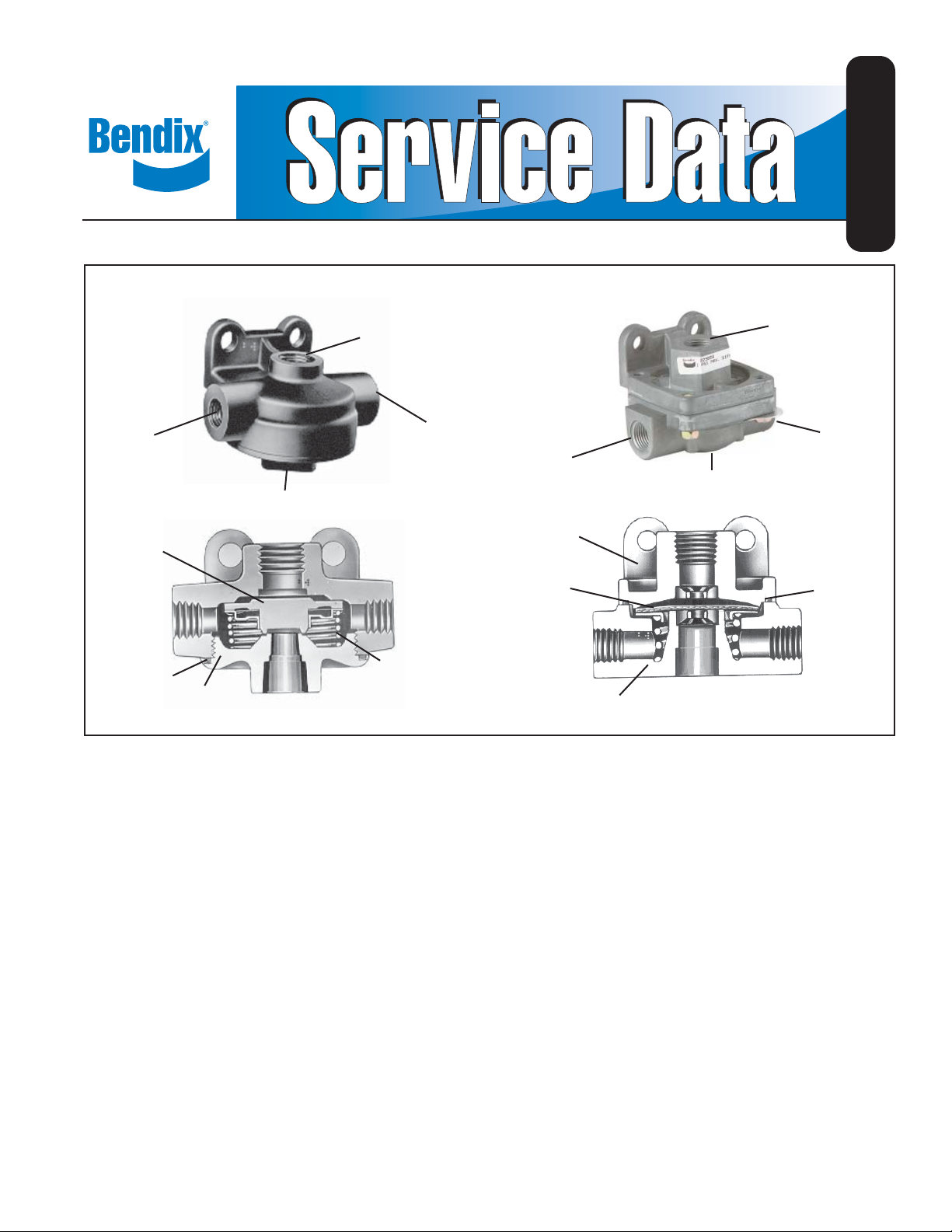
Delivery Port
Diaphragm
O-Ring
FIGURE 1
QRV
™
Quick Release Valve
Supply Port
Exhaust Port
Cover
Release Valve
Delivery Port
Spring
QRV™ Quick
QR-1® Quick Release Valve
Delivery
Port
Exhaust Port
Cover
Diaphragm
Body
Supply Port
Delivery Port
O-Ring
QR-1® Quick
Release Valve
DESCRIPTION
The function of the quick release valve is to speed up the
exhaust of air from the air chambers. It is mounted close
to the chambers it serves. In its standard confi guration the
valve is designed to deliver within 1 psi of control pressure
to the controlled device; however, for special applications
the valve is available with greater differential or zero
hysteresis. QR-1® valves also come with optional noise
reducing foam crosses or silencers.
Reference Figure 1, two styles of quick release valves
are available and are functionally the same; the QRV
valve, which is of older design and utilizes a spring and
spring seat, and the QR-1® valve, which in its standard
confi guration does not employ a spring or spring seat.
(Note: QR-1® valves with a pressure differential employ a
spring and spring seat.)
Porting consists of one supply port, two delivery ports and
one exhaust port.
™
OPERATION
When a brake application is made, air pressure enters
the supply port; the diaphragm moves down, sealing the
exhaust. At the same time, air pressure forces the edges of
the diaphragm down and air fl ows out the delivery ports.
When air pressure being delivered (beneath the diaphragm)
equals the pressure being delivered by the brake valve
(above the diaphragm), the outer edge of the diaphragm will
seal against the body seat. The exhaust port is still sealed
by the center portion of the diaphragm when the supply air is
released; the air pressure above the diaphragm is released
back through the brake valve exhaust; air pressure beneath
the diaphragm forces the diaphragm to rise, opening the
exhaust, allowing delivery air to exhaust.
1
Page 2

PREVENTIVE MAINTENANCE
Important: Review the Bendix Warranty Policy before
performing any intrusive maintenance procedures. The
warranty may be voided if intrusive maintenance is
performed during the warranty period.
No two vehicles operate under identical conditions, as
a result, maintenance intervals may vary. Experience is
a valuable guide in determining the best maintenance
interval for air brake system components. At a minimum,
the QR-1
3600 operating hours, whichever comes fi rst, for proper
operation. Should the QR-1® valve not meet the elements
of the operational tests noted in this document, further
investigation and service of the valve may be required.
®
valve should be inspected every 12 months or
OPERATING AND LEAKAGE TESTS
While holding a foot brake valve application:
1. Coat the exhaust port with a soap solution; leakage of
a 1" bubble in 3 seconds is permitted.
2. Coat the body and cover with a soap solution. No
leakage is permitted between body and cover.
If the valve does not function as described, or if leakage
is excessive, it is recommended that it be replaced with
a new or remanufactured unit, or repaired with genuine
Bendix® parts.
GENERAL SAFETY GUIDELINES
WARNING! PLEASE READ AND FOLLOW
THESE INSTRUCTIONS TO A VOID PERSONAL
INJURY OR DEATH:
When working on or around a vehicle, the following
general precautions should be observed at all times.
1. Park the vehicle on a level surface, apply the parking
brakes, and always block the wheels. Always wear
safety glasses.
2. Stop the engine and remove ignition key when
working under or around the vehicle. When
working in the engine compartment, the engine
should be shut off and the ignition key should be
removed. Where circumstances require that the
engine be in operation, EXTREME CAUTION should
be used to prevent personal injury resulting from
contact with moving, rotating, leaking, heated or
electrically charged components.
3. Do not attempt to install, remove, disassemble
or assemble a component until you have read
and thoroughly understand the recommended
procedures. Use only the proper tools and observe
all precautions pertaining to use of those tools.
4. If the work is being performed on the vehicle’s
air brake system, or any auxiliary pressurized air
systems, make certain to drain the air pressure from
all reservoirs before beginning ANY work on the
vehicle. If the vehicle is equipped with an AD-IS®
air dr yer system or a dr yer reser voir module, be
sure to drain the purge reservoir.
5. Following the vehicle manufacturer’s recommended
procedures, deactivate the electrical system in a
manner that safely removes all electrical power
from the vehicle.
6. Never exceed manufacturer’s recommended
pressures.
7. Never connect or disconnect a hose or line
containing pressure; it may whip. Never remove
a component or plug unless you are certain all
system pressure has been depleted.
8. Use only genuine Bendix
components and kits. Replacement hardware,
tubing, hose, fi ttings, etc. must be of equivalent
size, type and strength as original equipment and
be designed specifi cally for such applications and
systems.
9. Components with stripped threads or damaged
parts should be replaced rather than repaired. Do
not attempt repairs requiring machining or welding
unless specifi cally stated and approved by the
vehicle and component manufacturer.
10. Prior to returning the vehicle to service, make
certain all components and systems are restored
to their proper operating condition.
11. For vehicles with Automatic T raction Control (A TC),
the ATC function must be disabled (ATC indicator
lamp should be ON) prior to performing any vehicle
maintenance where one or more wheels on a drive
axle are lifted off the ground and moving.
®
replacement parts,
REMOVING AND INSTALLING
REMOVING
1. Block vehicle wheels and/or hold vehicle by means
other than air brakes.
2. Drain all air brake system reservoirs.
3. Disconnect air lines from valve.
4. Remove mounting bolts, then the valve.
INSTALLING
Mount the valve with exhaust port pointing down; securely
tighten mounting bolts.
Connect the air lines to valve (brake valve application line
to top port; brake chamber line to side ports.)
2
Page 3

DISASSEMBLY
QRV™ VALVE
1. Using a wrench on square portion of exhaust port,
remove the cover.
2. Remove the spring, spring seat and diaphragm.
Remove the cover o-ring.
ASSEMBLY
QRV™ VALVE
1. Position the spring seat over the diaphragm and then
install it into body.
2. Install the spring and cover o-ring.
3. Install the cover; tighten securely. (Torque to 150-400
inch pounds.)
QR-1® VALVE
1. Remove the four screws.
2. Remove the spring and spring seat (if so equipped).
3. Remove the diaphragm.
4. Remove the cover o-ring.
CLEANING AND INSPECTION
Clean all metal parts in mineral spirits. Wipe all rubber
parts clean.
It is recommended that all rubber parts and any other part
showing signs of wear or deterioration be replaced with
genuine Bendix® parts.
®
VALVE
QR-1
1. If the valve is equipped within spring and spring seat:
a. Position the spring in body.
b. Position the diaphragm over spring seat.
c. Install the o-ring in the cover groove; install the
cover and tighten the screws evenly and securely.
(Torque to 30-60 inch pounds.)
2. If the valve is not equipped with spring and spring
seat:
a. Install the diaphragm.
b. Install the o-ring in the cover groove; install the
cover and tighten the screws evenly and securely.
(Torque to 30-60 inch pounds.)
3. Perform tests as outlined in “Operating and Leakage
Tests” section.
3
Page 4

4
BW1442 © 2010 Bendix Commercial Vehicle Systems LLC. All rights reserved. 5/2010 Printed in U.S.A.
 Loading...