

Page 1
Manual
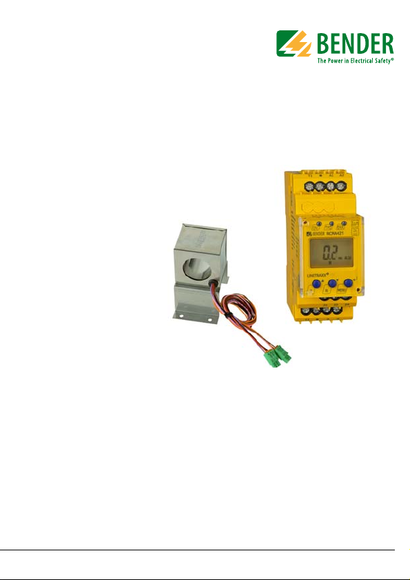
RCMA421H
WN-35BS
Residual current monitor
for monitoring AC, DC and pulsed DC currents
in earthed and resistance earthed systems
Software version D309 V1.0x
RCMA421H_D00069_00_M_XXEN/05.2014
Page 2

Bender GmbH & Co. KG
P.O. Box 1161 • 35301 Gruenberg • Germany
Londorfer Str. 65 • 35305 Gruenberg • Germany
Tel.: +49 6401 807-0
Fax: +49 6401 807-259
E-Mail: info@bender.de
Web: http://www.bender.de
© Bender GmbH & Co. KG
All rights reserved.
Reprinting only with permission
of the publisher.
Subject to change!
Page 3

Table of Contents
1. Making effective use of this document ....................................................... 5
1.1 How to use this manual ................................................................................. 5
1.2 Intended use ...................................................................................................... 5
2. Safety instructions ........................................................................................... 7
2.1 General safety instructions ........................................................................... 7
2.2 Work activities on electrical installations ................................................ 7
2.3 Device-specific safety information ............................................................ 8
3. Function ............................................................................................................. 9
3.1 Device features ................................................................................................. 9
3.2 Description of function .................................................................................. 9
3.2.1 Transformer monitoring ............................................................................. 10
3.2.2 Quick query of the rated residual operating current ....................... 10
3.2.3 Self test, automatic ....................................................................................... 11
3.2.4 Self test, manual ............................................................................................ 11
3.2.5 Malfunction ..................................................................................................... 11
3.2.6 Password protection (on, OFF) ................................................................. 11
3.2.7 Factory setting FAC ...................................................................................... 12
3.2.8 Erasable history memory HiS .................................................................... 12
4. Installation and connection ......................................................................... 13
4.1 Dimension diagrams .................................................................................... 13
4.2 Factory setting ............................................................................................... 16
4.3 Commissioning .............................................................................................. 16
5. Operation and configuration ....................................................................... 17
5.1 Getting to know the user interface ......................................................... 17
5.2 Understanding information on the standard display ...................... 18
5.3 Getting to know buttons and button functions ................................ 19
RCMA421H_D00069_00_M_XXEN/05.2014
3
Page 4

Table of Contents
5.4 Starting a manual self test .......................................................................... 20
5.5 Erasing the fault memory ........................................................................... 20
5.6 Calling up and exiting the menu ............................................................. 20
5.7 Making settings in the menu .................................................................... 21
5.7.1 Selecting menus ............................................................................................ 21
5.7.2 Querying the software version with the InF menu ........................... 22
5.7.3 Making settings in the SEt menu ............................................................. 23
5.7.4 Querying and erasing the fault memory in the HIS menu ............. 25
6. Technical data ................................................................................................ 27
6.1 Data RCMA421H-D-2 in table form ......................................................... 27
6.2 Error codes ....................................................................................................... 30
6.3 Recommended contactors ........................................................................ 31
6.4 Response times of the RCMA421H system plus
contactor in accordance with UL943 ..................................................... 32
6.5 Ordering information ................................................................................... 33
6.6 Standards, approvals and certifications ................................................ 33
6.7 Label for modified versions ....................................................................... 34
INDEX .................................................................................................................... 35
4
RCMA421H_D00069_00_M_XXEN/05.2014
Page 5
1. Making effective use of this document
1.1 How to use this manual
This manual has been designed for electrically skilled persons
working in electrical engineering and electronics!
To make it easier for you to understand and revisit certain sections of text and
instructions in the manual, we have used symbols to identify important instructions and information. Examples of how such symbols are used appear
below:
The warning symbol indicates a potential dangerous
situation that may result in bodily injury and/or damage
to property.
Observe the associated safety instructions.
Information intended to assist the user to make optimum
use of the product are marked with the Info symbol.
1.2 Intended use
The AC/DC sensitive residual current monitor RCMA421H with its measuring
current transformer WN-35BS is used to monitor earthed and resistiveearthed systems (TN and TT systems) in which DC and AC fault currents may
occur. These systems involve loads with six-pulse bridge rectifiers or halfwave rectifiers with smoothing, e.g. converters and chargers.
In the event of a rated residual current I
alarm relay and the associated contactor in accordance with the operating
time specified in UL943.
of 6 mA, the device will switch an
Δ
n
RCMA421H_D00069_00_M_XXEN/05.2014
5
Page 6

Making effective use of this document
6
RCMA421H_D00069_00_M_XXEN/05.2014
Page 7
2. Safety instructions
2.1 General safety instructions
In addition to these operating instructions, the "Important safety instructions
for Bender products“, which are also included in the scope of supply, are an integral part of the device documentation.
2.2 Work activities on electrical installations
Only skilled persons are permitted to carry out the work necessary to
install, commission and run a device or system.
Compliance with applicable regulations governing work on electrical
installations, and with the regulations derived from and associated
with them, is mandatory. EN 50110 is of particular importance in this
regard.
Failure to carry out work on electrical installations properly and correctly can put life and limb at risk!
If the device is being used in a location outside the Federal Republic of
Germany, the applicable local standards and regulations must be complied with. European standard EN 50110 can be used as a guide.
RCMA421H_D00069_00_M_XXEN/05.2014
7
Page 8

2.3 Device-specific safety information
According to UL943 every residual current monitor and
the associated measuring current transformer is to be
tested in pairs. The relevant serial number for the transformer is imprinted on the enclosure of the RCMA421H.
The residual current monitor and the measuring current
transformer assigned to it may only be used or interchanged in pairs.
Safety instructions
8
RCMA421H_D00069_00_M_XXEN/05.2014
Page 9

3. Function
3.1 Device features
AC/DC sensitive residual current monitor with external 35 mm measur-
ing current transformer
Can be used in conjunction with a contactor
Rated residual operating current I
Operating time acc. to UL943
r.m.s. value measurement, frequency range 0…150 Hz
Measured value display via multi-functional LCD
Alarm signalling via LEDs (TPD, ERR) and K2 changeover contact
Password protection to prevent unauthorised changes being made to
device settings
Permanent fault memory
N/C operation of alarm relay
Device test when the power supply voltage is connected
Automatic self test every 24 h
CT connection monitoring
Internal test circuit acc. to UL943 without additional external compo-
nents
External test and reset button can be connected
N-PE conductor monitoring on the load side
3.2 Description of function
The RCMA421H runs a device test when the power supply voltage is connected. During the start-up phase, the TRP LED lights up, the alarm LED ERR flashes
and the alarm relay switches to the alarm setting.
Once the device test has been completed successfully, the ERR alarm LED will
stop flashing, the TPD LED will go out and the alarm relay will return to the
normal setting.
= 6 mA acc. to UL943
Δn
RCMA421H_D00069_00_M_XXEN/05.2014
9
Page 10

Function
The device will check the circuit for the presence of residual currents even during the self test.
An external measuring current transformer (e.g. WN-35BS) is used for residual
current measurement. The actual measured value is indicated on the LCD. If
the rated residual operating current of 6 mA is exceeded, the alarm relay K2
will change to the alarm state and the TRP alarm LED will light up.
Once the alarm relay has switched, the residual current must fall to less than
the rated residual operating current.
If it does not, error code E.04 will appear on the display and the ERR alarm LED
will flash. This means that the connected contactor has not shut down the
faulty circuit.
If the residual current falls below the release value, the error will continue to
be signalled due to the permanently activated fault memory. The alarm relay
K2 will not switch back to the initial state and the TRP alarm LED will not go
out until the reset button R is pressed or the power supply voltage is interrupted.
Parameters are assigned to the device via the LCD and the control buttons on
the front panel; this function can be password-protected.
3.2.1 Transformer monitoring
The connections to the measuring current transformer are checked periodically every 10 s for short and open circuits. In the event of an error, the alarm
relay K2 will switch, the red TPD alarm LED will light up and the yellow ERR
alarm LED will flash (error codes E.01 or E.03). Once the error has been eliminated, the alarm LEDs and the alarm relay will remain in the alarm state. Pressing the reset button R or sending a reset command via the RS-485 interface
will switch K2 back to its initial state and the alarm LEDs will go out.
3.2.2 Quick query of the rated residual operating current
When the display is in standard mode, the rated residual operating current IΔn
= 6 m A can be qu erie d by pres sing the U p or Down butt on (< 1.5 s). S witc hing
to menu mode is not necessary. Quick query mode can be exited by pressing
Enter (< 1.5 s).
10
RCMA421H_D00069_00_M_XXEN/05.2014
Page 11

Function
3.2.3 Self test, automatic
The device runs a self test every 24 h. Any internal malfunctions detected are
shown on the display as error codes. The automatic self test is carried out
without internal fault current. The alarm relay is not switched during the 24-h
test.
3.2.4 Self test, manual
The device runs a self test when the test button is pressed (> 1.5 s). Any internal malfunctions detected are shown on the display as error codes.
Whilst the test button T is pressed, all display elements available for this device are shown. When the button is released, the tES test symbol appears and
the manual self test commences.
During the manual self test, an internal test current of approx. 7 mA is evaluated. Consequently, the TPD alarm LED lights up and the alarm relay switches.
Once the alarm relay has switched, the residual current must fall to less than
the rated residual operating current. If it does not, error code E.04 will appear
on the display to indicate that the connected contactor has not shut down the
load circuit.
If the self test has been successfully and the reset button R is pressed, the
alarm LEDs will go out and the relay will switch to its initial state.
If the self test has not been successfully, the TPD alarm LED will light, the ERR
alarm LED will flash, the alarm relay will switch to the alarm state and an error
code will be displayed.
3.2.5 Malfunction
In the event of an internal malfunction, the TPD alarm LED will light and the
ERR alarm LED will flash. An error code will appear on the display until the fault
is removed. Refer to page 30 for details about error codes.
3.2.6 Password protection (on, OFF)
If password protection has been activated (on), settings can only be made
subject to the correct password being entered (0…999).
RCMA421H_D00069_00_M_XXEN/05.2014
11
Page 12

Function
3.2.7 Factory setting FAC
Activating the factory setting will reset all modified settings, with the exception of the device address, to the default upon delivery.
3.2.8 Erasable history memory HiS
The first alarm value to occur is written to this memory. The memory can be
erased via the HiS menu.
12
RCMA421H_D00069_00_M_XXEN/05.2014
Page 13

4. Installation and connection
36 mm
90 mm
1
2
3
Zubehör/
Accessory
100 mm
116 mm
Make sure that the installation area has been de-energised and
ensure compliance with the regulations for working on electrical installations.
4.1 Dimension diagrams
RCMA421H dimension diagram and drawing for screw fixing
The front plate cover is easy to open at the lower part marked by an arrow.
RCMA421H_D00069_00_M_XXEN/05.2014
13
Page 14

Installation and connection
62
51,20
42
57
90
79
37
4
,
6
0
3
5
99,50
71
Dimension diagram for measuring current transformer WN-35BS
Dimensions in mm
14
RCMA421H_D00069_00_M_XXEN/05.2014
Page 15

Installation and connection
T1 T2
K1
K1
T1
A2A1
T2
1
21 2422
WN-...BS
6
<
U
k1
k2
T
I1
I2
T
3,15 A
3,15 A
T
T/R R
T T/R R
1. Mounting on a DIN rail:
Snap the mounting clip at the rear of the device onto the DIN rail so
that it sits securely.
Screw fixing:
Using the tool, position the rear mounting clips (a second mounting
clip is required, see the ordering information) so that it protrudes over
the enclosure. Fix the device in place with two M4 screws.
2. Wiring
The device must be wired as illustrated in the wiring diagram (example).
Terminal Connections
A1, A2 Connection to the power supply
1 Bush for measuring current transformer's connecting cable
T, T/R, R Connections for external test and reset button
21, 22, 24 Alarm relay K2: Connection to contactor or load switch
T1, T2 Test connections for internal monitoring circuit
WN-…BS Measuring current transformers
K1 Recommended contactors are listed in the table on page 31
RCMA421H_D00069_00_M_XXEN/05.2014
15
Page 16

Installation and connection
Conductor colours for measuring current transformer
Colour
brown K1 black I1
orange K2 red I2
pink T violet T
Pin
assignment
Colour
Pin
assignment
4.2 Factory setting
Rated residual operating current, fixed value:
Hysteresis, fixed value:
Fault memory M:
Mode of operation K2:
Password:
6 mA
15 %
permanently activated
permanent
N/C operation (n.c.)
0, deactivated (Off)
4.3 Commissioning
Checks must be carried out prior to commissioning to ensure that the residual
current monitor, the external measuring current transformer and the associated contactors and peripherals have been connected correctly.
Incorrect connections can lead to personal injury and damage
to equipment or property!
16
RCMA421H_D00069_00_M_XXEN/05.2014
Page 17

5. Operation and configuration
1 Green Power ON LED:
Lights up when the power supply voltage
is connected and the device is running.
2 Red TPD alarm LED:
Lights up when the rated residual operating current I
Δn
is exceeded.
3 Yellow ERR alarm LED:
Flashes in the event of system errors. An
error code will appear on the display, e.g.
E.03
4DISPLAY:
Displays operating information.
5 ENTER (< 1.5 s) / MENU (> 1.5 s) button:
Press this button to apply entries and
changes and call up the menu.
6 DOWN (< 1.5 s) / RESET (> 1.5 s) button:
Press this button to reduce input values
and navigate through the menu, as well
as to perform a reset.
7 UP (< 1.5 s) / TEST (> 1.5 s) button:
Press this button to increase input values
and navigate through the menu, as well
as to run a manual self test.
Fig. 5.1: Us er interface
5.1 Getting to know the user interface
RCMA421H_D00069_00_M_XXEN/05.2014
17
Page 18

Operation and configuration
Fig. 5.1: Standard display
1 Measured value display in mA:
2 Current type display AC / DC
3 Password protection activated
4 Fault memory activated
5.2 Understanding information on the standard display
The actual measured residual current is displayed by default.
Press the Up or Down button to display the factory-set rated residual operating current I
. Pressing the Enter button restores the measured value.
Δn
In standard operation, the display can be toggled to the fixed
rated residual operating current I
button.
of 6 mA using the Up/Down
Δ
n
18
RCMA421H_D00069_00_M_XXEN/05.2014
Page 19

Operation and configuration
T
R
MENU
5.3 Getting to know buttons and button functions
The table below lists the functions of the buttons when navigating through
the display, navigating through the menu and when making settings. From
"chapter 5.7 Making settings in the menu" in the menu onwards, just the relevant button symbol is used to indicate that buttons have been pressed.
Button Button symbol Func tion
Call up next display
Go to the next menu/submenu/cat-
egory item
Up/
Tes t
Down/
Reset
ENTER/
Menu
Activate parameter
Change (increase) parameter value
Press and hold down button for
more than 1.5 seconds: carry out the
manual self test.
Call up next display
Go to next menu/submenu
Deactivate parameter
Change (reduce) parameter value
Press and hold down button for
more than 1.5 seconds: erase fault
memory
Call up menu/submenu
Apply modified parameter value
Press and hold down button for
more than 1.5 seconds: Call up
menu/exit menu/go to next highest
submenu
RCMA421H_D00069_00_M_XXEN/05.2014
19
Page 20

Operation and configuration
5.4 Starting a manual self test
You can start a self test manually. During the test, any internal malfunctions
detected are shown on the display as error codes. The alarm relay will be
switched.
To start a self test manually:
Press and hold down the test button T (UP) or external test button for
more than 1.5 seconds.
The text “tES“ appears on the display along with all available display elements.
5.5 Erasing the fault memory
The device has an erasable fault memory.
To erase the fault memory:
Press and hold down the reset button "R" (DOWN) or external reset but-
ton for more than 1.5 seconds.
5.6 Calling up and exiting the menu
To call up the menu:
Press and hold down the MENU (ENTER) button for more than 1.5 sec-
onds.
To exit the menu again:
Press and hold down the MENU (ENTER) button again for more than 1.5
seconds.
20
The areas of the display which can be configured flash! This is
indicated by an oval marker in the illustrations below. Press and
hold down the MENU button > 1.5 s to enter menu mode.
RCMA421H_D00069_00_M_XXEN/05.2014
Page 21

Operation and configuration
5.7 Making settings in the menu
5.7.1 Selecting menus
Press and hold down the MENU button for more than 1.5 seconds to call up
the menu. Menus are available for a variety of settings. In turn, each menu has
a number of submenus. The UP/DOWN buttons can be used to navigate between menus. Press and hold down the ENTER button for less than 1.5 seconds to call up a menu. Press and hold down the ENTER button for more than
1.5 seconds to go to the next highest menu.
Menu/Button to call
RCMA421H_D00069_00_M_XXEN/05.2014
Description/Configurable parameters
Query software version
1. Press the UP/DOWN buttons to go to the menu
Set bus address
2. Press the UP/DOWN buttons to go to the menu
Assign device control parameters
Activate or deactivate password protection, change
password
Restore factory settings
Service menu SyS (locked)
3. Press the UP/DOWN buttons to go to the menu
Query saved alarm value, erase history memory
21
Page 22

Operation and configuration
Menu/Button to call
Description/Configurable parameters
4. Press the UP/DOWN buttons to go to the menu
Go to the next highest menu level (Back)
5.7.2 Querying the software version with the InF menu
1. Select the InF menu
2. Confirm with Enter
The software version (e.g.: d309-1.00) is displayed as running text. Once all information is showing on the display, you can use the UP/DOWN buttons to select individual items.
22
RCMA421H_D00069_00_M_XXEN/05.2014
Page 23

Operation and configuration
5.7.3 Making settings in the SEt menu
This menu can be used to activate password protection, to modify the password or to deactivate password protection. It is also where the device can be
reset to the factory settings.
1. Select the SEt menu.
2. Make changes to parameters as illustrated.
To go back to the menu level, press and hold down the ENTER button for more
than 1.5 seconds once you have modified the parameter(s).
SEt menu
1. Activate
password
protection
and assign
password (3digit numerical code)
2. Change password
RCMA421H_D00069_00_M_XXEN/05.2014
Select submenu
Change/activate/
deactivate param.
Change parameter value
display
Change/apply
param.
23
Page 24

Operation and configuration
SEt menu
3. Deactivate
password
protection
4. Switch submenu
5. Restore
factory setting
6. Switch submenu
Select submenu
Change/activate/
deactivate param.
Change parameter value
display
"run" appears on the display and
the device is reset to the factory
settings automatically.
Change/apply
param.
7. System menu
(is locked)
24
RCMA421H_D00069_00_M_XXEN/05.2014
Page 25

Operation and configuration
SEt menu
8. Switch submenu
9. Go back to
SEt menu
Select submenu
Change/activate/
deactivate param.
Change parameter value
display
Change/apply
param.
5.7.4 Querying and erasing the fault memory in the HIS menu
1. Select the HIS menu.
2. Select the saved error and erase if applicable.
3. To go back to the menu level, press and hold down the ENTER button
for more than 1.5 seconds.
HiS menu
1. Error:
Rated residual operating current exceeded
2. Switch error display
3. Error code E.03
see page 30
Error display/Submenu
4. Switch error display
RCMA421H_D00069_00_M_XXEN/05.2014
25
Page 26

Operation and configuration
HiS menu
5. Erase fault memory
6. Switch error display
7. Go back to HiS menu
Error display/Submenu
26
RCMA421H_D00069_00_M_XXEN/05.2014
Page 27

6. Technical data
6.1 Data RCMA421H-D-2 in table form
( )* = factory setting
Insulation coordination acc. to IEC 60664-1 / IEC 60664-3
RCMA421H-D-2:
Rated insulation voltage ....................................................................................................................................... 250 V
Overvoltage category/ pollution degree................................................................................................................... III/3
Rated impulse voltage.............................................................................................................................................. 4 kV
Protective separation (reinforced insulation) between.......................................... (A1, A2) - (k/l, T/R) - (21, 22, 24)
Voltage tests according to IEC 61010-1.............................................................................................................. 2.21 kV
Supply voltage
Supply voltage range U
Supply voltage U
Frequency range U
Power consumption ......................................................................................................................................... ≤ 6.5 VA
Measuring circuit
External measuring current transformer......................................................................................................... WN-35BS
Rated voltage (measuring current transformer) .................................................................................................. 2.5 kV
Rated frequency ........................................................................................................................................... 0…150 Hz
AC/DC measuring range .............................................................................................................................. 0…40 mA
Relative uncertainty 0…20 Hz ....................................................................................................... -33 %…+100 %
Relative uncertainty 20…90 Hz ................................................................................................................. 0…-33 %
Relative uncertainty 90…150 Hz .................................................................................................................. ± 17.5 %
Response value
Rated residual operating current I
Time behaviour
Start-up delay t .................................................................................................................... operating time t
Operating time t
................................................................................................................. AC/DC 100…250 V
s
............................................................................................................................. AC/DC 70…300 V
s
................................................................................................................................... 42…460 Hz
s
.................................................................................................................... 6 mA
Δn
+ 3.2 s
acc. to UL943 ........................................................................................... see diagram on page 32
ae
ae
RCMA421H_D00069_00_M_XXEN/05.2014
27
Page 28

Technical data
Displays, memory
Display range. AC/DC measured value ........................................................................................................ 0…40 mA
Resolution of setting ........................................................................................................................................... 0.1 mA
Error of indication 0…20 Hz ...................................................................................... -33 %…+100 % / ± 2 digits
Error of indication 20…90 Hz .................................................................................................. 0…20% / ± 2 digits
Error of indication 90…150 Hz ................................................................................................. ± 17.5 % / ± 2 digits
Error of indication at I
< 2 mA..................................................................................................................... ± 7 digits
Δ
Measured value memory for alarm value (HiS) ................................................................... Measured values data set
Password .................................................................................................................................... off / 0…999/ 0 (off)*
Cable length, WN-35BS measuring current transformer
Cable length ............................................................................................................................................................ 0.5 m
Switching elements
Number of switching elements .................................................................................................. 1 changeover contact
Operating principle ........................................................................................................................... N/C operation n.c.
Electrical service life under rated operating conditions........................................................... 10 000 switching cycles
Contact data acc. to IEC 60947-5-1
Utilisation category...............................................................AC-13..........AC-14......... DC-12 .........DC-12 ....... DC-12
Rated operational voltage......................................................230 V ..........230 V ............ 24 V .......... 110 V ........ 220 V
Rated operational voltage UL ................................................200 V .......... 200 V ............ 24 V .......... 110 V ........ 200 V
Rated operational current..........................................................5 A...............3 A.............. 1 A ...........0.2 A ......... 0.1 A
Minimum contact rating ........................................................................................................... 1 mA at AC/DC ≥ 10 V
Environment / EMC
EMC ....................................................................................................................................................................... UL943
Operating temperature ...................................................................................................................... -35 ºC…+66 ºC
Climatic class acc. to IEC 60721
Stationary use (IEC 60721-3-3) ........................................................ 3K5 (except condensation and formation of ice)
Transport (IEC 60721-3-2) ............................................................... 2K3 (except condensation and formation of ice)
Long-term storage (IEC 60721-3-1) ................................................1K4 (except condensation and formation of ice)
Classification of mechanical conditions acc. to IEC 60721:
Stationary use (IEC 60721-3-3) ...............................................................................................................................3M4
Transport (IEC 60721-3-2) ..................................................................................................................................... 2M2
Long-term storage (IEC 60721-3-1) ...................................................................................................................... 1M3
28
RCMA421H_D00069_00_M_XXEN/05.2014
Page 29

Technical data
Connection
For UL application................................................................................................ use 60/70°C copper conductors only
Connection type ............................................................................................................................... screw terminals
rigid/ flexible/ conductor sizes ................................................................. 0.2…4 / 0.2…2.5 mm
2
/ AWG 24…12
Multi-conductor connection (2 conductors with the same cross section)
rigid, flexible .......................................................................................................................0.2…1.5 / 0.2…1.5 mm
Stripped length ............................................................................................................................................. 8…9 mm
Tightening torque.................................................................................................................................... 0.5…0.6 Nm
Connection type ....................................................................................................................... push-wir e terminals
Connection properties:
rigid ........................................................................................................................... 0.2…2.5 mm2 (AWG 24…14)
Flexible without ferrules ........................................................................................... 0.2…2.5 mm
Flexible with ferrules ................................................................................................ 0.2…1.5 mm
2
(AWG 24…14)
2
(AWG 24…16)
Stripped length ................................................................................................................................................... 10 mm
Opening force........................................................................................................................................................... 50 N
Test opening, diameter....................................................................................................................................... 2.1 mm
Other
Operating mode continuous operation
Position of normal use.......................................................................................................................... display-oriented
Degree of protection, internal components (IEC 60529) .........................................................................................IP30
Degree of protection, terminals (IEC 60529)............................................................................................................IP20
Enclosure material .................................................................................................................................... polycarbonate
Flammability class .............................................................................................................................................UL94V-0
DIN rail mounting acc. to................................................................................................................................. IEC 60715
Screw fixing.......................................................................................................................... 2 x M4 with mounting clip
Software version ............................................................................................................................................ D309 V1.0
Weight RCMA421H ........................................................................................................................................... ≤ 150 g
Weight WN-35BS ............................................................................................................................................. ≤ 355 g
2
( )* = factory setting
RCMA421H_D00069_00_M_XXEN/05.2014
29
Page 30

Technical data
6.2 Error codes
If, contrary to expectations, a device error should occur, error codes will appear on the display. Some of these are described below:
Error code Meaning
Connection error: no transformer
E.01
E.02
E.03
E.04
E…
Action:
Check transformer connection for short circuit or open circuit,
from T to T and from k2 to l2.
Connection error: connection system
(after finishing manual self test)
Action:
Check transformer connection for short-circuit or open circuit.
- Check correct connection, from T1 to T2.
Connection error: short-circuit transformer
Action:
Check transformer connection for short-circuit or open circuit.
Error K1/Q1(following powering up the device)
Action:
Check contactor: e.g. contacts sticking, release coil faulty
Error codes > 04:
Action:
Perform a reset. Restore the device to the factory setting.
Should the error persist, contact Bender Service.
After removing the CT mains connector, the error code E.03 / E.04 alternately
appears on the display.
The error code will be erased automatically once the error has been
eliminated.
30
RCMA421H_D00069_00_M_XXEN/05.2014
Page 31

Technical data
Main contact
A16-30-10-84 3 1
A26-30-10-84 3 1
A40-30-10-84 3 1
A75-30-00-84 3
A110-30-00-84 3
A
145-30-00-84 3
A16-30-10-34 3 1
A26-30-10-34 3 1
A40-30-10-34 3 1
A75-30-00-34 3
A110-30-00-34 3
A
145-30-00-34 3
A16-40-00-84 4
A26-40-00-84 4
A45-40-00-84 4
A75-40-00-84 4
EK150* -40-22 4 2 2
A16-40-00-34 4
A26-40-00-34 4
A45-40-00-34 4
A75-40-00-34 4
EK150** -40-22 4 2 2
Contactor
type
Auxilary contact
6.3 Recommended contactors
The ABB types listed below have undergone performance testing:
RCMA421H_D00069_00_M_XXEN/05.2014
31
Page 32

Technical data
30; 0,560
6; 5,594
264; 0,0250
0,01
0,10
1,00
10,00
0 20 40 60 80 100 120 140 160 180 200 220 240 260
I / mA
T / s
CLASS A 60Hz ac
6.4 Response times of the RCMA421H system plus contactor in accordance with UL943
32
RCMA421H_D00069_00_M_XXEN/05.2014
Page 33

Technical data
6.5 Ordering information
RCMA421H-D2
Rated residual operating current I
Rated frequency 0…150 Hz
Supply voltage U
Art. No.: with screw terminal
with push-wire terminal
*
s
*Absolute values of the voltage range
Δn
6 mA
AC/DC 70…300 V
AC 42…460 Hz
B 9404 3019
B 7404 3019
External measuring current transformer
Type Internal diameter (mm) Art. No.
WN-35BS 35 B 9808 0044
RCMA421H accessories
Mounting clip for screw fixing (1 per device)........................................................................................... B 9806 0008
6.6 Standards, approvals and certifications
RCMA421H_D00069_00_M_XXEN/05.2014
33
Page 34

Technical data
6.7 Label for modified versions
There will only be a label in this field if the device is different from the standard
version.
34
RCMA421H_D00069_00_M_XXEN/05.2014
Page 35

INDEX
A
Accessories 33
B
Button functions 19
C
Commissioning 16
Conductor colours for measuring current
transformer
D
Description of function 9
Device features
Device test
Dimension diagrams
E
Error codes 30
F
Factory setting 12, 16
H
HiS menu 25
History memory
How to use this manual
16
9
9
13
12
5
I
Installation and connection 13
M
Malfunction 11
Manual, target group
Menu, settings
Multi-conductor connection
O
Operation and configuration 17
Ordering information
P
Parameter setting
- Activating or deactivating the password protection
Password protection
Push-wire terminal
Q
Querying and erasing the fault memory 25
Quick query of the rated residual operating
current
R
Recommended contactors 31
Response times
Restore factory settings
5
21
29
33
23
11
29
10
32
24
RCMA421H_D00069_00_M_XXEN/05.2014
35
Page 36

RS-485 interface 13
S
screw terminals 29
Self test, automatic
Self test, manual
Set bus address
SEt menu
T
Technical data 27
To call up the menu
To exit the menu
W
Wiring diagram 15
Work activities on electrical installations
11
11, 20
23
23
20
20
7
36
RCMA421H_D00069_00_M_XXEN/05.2014
Page 37

37
RCMA421H_D00069_00_M_XXEN/05.2014
Page 38

38
RCMA421H_D00069_00_M_XXEN/05.2014
Page 39

Page 40

D0006100MXXEN
Bender GmbH & Co. KG
P.O. Box 1161 • 35301 Gruenberg • Germany
Londorfer Str. 65 • 35305 Gruenberg • Germany
Tel.: +49 6401 807-0
Fax: +49 6401 807-259
E-Mail: info@bender.de
Web: http://www.bender.de
 Loading...