

Bender W1-S35, W0-S20, W2-S70, W3-S105, W5-S210 Series Manual
...
1
Messstromwandler
Bestimmungsgemäße Verwendung
Messstromwandler der Serie W.S… sind bestimmt für den Einsatz
in Verbindung mit:
● Differenzstrom-Überwachungssystemen der Serie
RCMS460/490 und RCMS470,
● Differenzstrom-Überwachungsgeräten der Serie RCM420,
RCM460 und RCM470,
● Isolationsfehler-Suchsystemen der Serie EDS460/490 und
EDS470.
Sicherheitshinweise allgemein
Montage, Anschluss und Inbetriebnahme nur durch Elektrofachkraft! Beachten Sie unbedingt:
● die bestehenden Sicherheitsvorschriften,
● das beiliegende Blatt "Wichtige sicherheitstechnische Hin-
weise für Bender-Produkte",
● die Technische Information „Wandlerinstallation“,
● die Bedienungsanleitung des verwendeten RCM(S) bzw.
EDS.
Funktionsbeschreibung
Die Messstromwandler der Serie W.S… sind hochempfindliche
Wandler, die AC-Ströme in Verbindung mit Differenzstrom-Überwachungs- und Auswertegeräten der Serie RCM bzw. RCMS in ein
auswertbares Messsignal umsetzen.
Weiterhin sind sie für den Einsatz mit Isolationsfehler-Suchsystemen für IT-Systeme EDS geeignet. Sie dienen zur Erfassung des
von einem Isolationsfehler-Prüfgerät PGH oder A-ISOMETER®
IRDH generierten Prüfstromes. Der Prüfstrom wird in Verbindung
mit Isolationsfehler-Auswertegeräten der Serie EDS in ein auswertbares Messsignal umgesetzt.
Die Verbindung zu den jeweiligen Geräten erfolgt über eine zweiadrige Leitung.
Montage und Anschluss
Montage
Messstromwandler der Serie W.S…sind für folgende Einbauarten
geeignet:
W0-S20 Schnellmontage auf Hutprofilschiene
nach IEC 60715
W1-S35 ... W5-S210 Schraubbefestigung
Stellen Sie vor Einbau des Gerätes und vor Arbeiten
an den Anschlüssen des Gerätes sicher, dass die Anlage spannungsfrei ist. Wird dies nicht beachtet, so besteht für das Personal die Gefahr eines elektrischen
Schlages. Außerdem drohen Sachschäden an der
elektrischen Anlage und die Zerstörung des Gerätes.
Measuring current transformer
Intended use
The measuring current transformers of the W.S… series are used
in combination with
● residual current monitoring systems of the RCMS460/490
and RCMS470 series,
● residual current monitors of the RCM420, RCM460 and
RCM470 series,
● insulation fault location systems of the EDS460/490 and
EDS470 series.
General safety information
Installation, connection and commissioning of electrical equipment shall only be carried out by qualified electricians. Particular
attention shall be paid to:
● the current safety regulations,
● the enclosed sheet „Important safety instructions for
Bender products“,
● the technical information „Installation instructions for
Bender measuring current transformers“,
● the operating manual of the connected RCM(S) or EDS.
Function
The measuring current transformers of the W.S… series are highsensitive transformers which in combination with residual current monitoring devices and evaluators of the RCM or RCMS series convert AC currents into evaluable measurement signals.
In combination with insulation fault location systems, the current
transformers are suitable for insulation fault location in IT systems. The current transformers measure the test current generated by the insulation fault test device PGH or by an A-ISOMETER
IRDH. In combination with insulation fault evaluators of the EDS
series, the test current is converted into evaluable measurement
signals.
The connection to the respective devices is via a two-wire cable.
Installation and connection
Installation
The measuring current transformers of the W.S… series are suited
for:
W0-S20 DIN rail mounting in compliance with
IEC 60715:1995-10
W1-S35 ... W5-S210 screw mounting
Prior to installation and before work activities are
carried out on the connecting cables, make sure that
the mains power is disconnected. Failure to comply
with this safety information may cause electric shock
to personnel. Furthermore, substantial damage to
the electrical installation and destruction of the device might occur.
W0-S20 ... W5-S210
TBP409002deen / 09.2009
Deutsch English
2
TBP409002deen / 09.2009
W0-S20 ... W5-S210
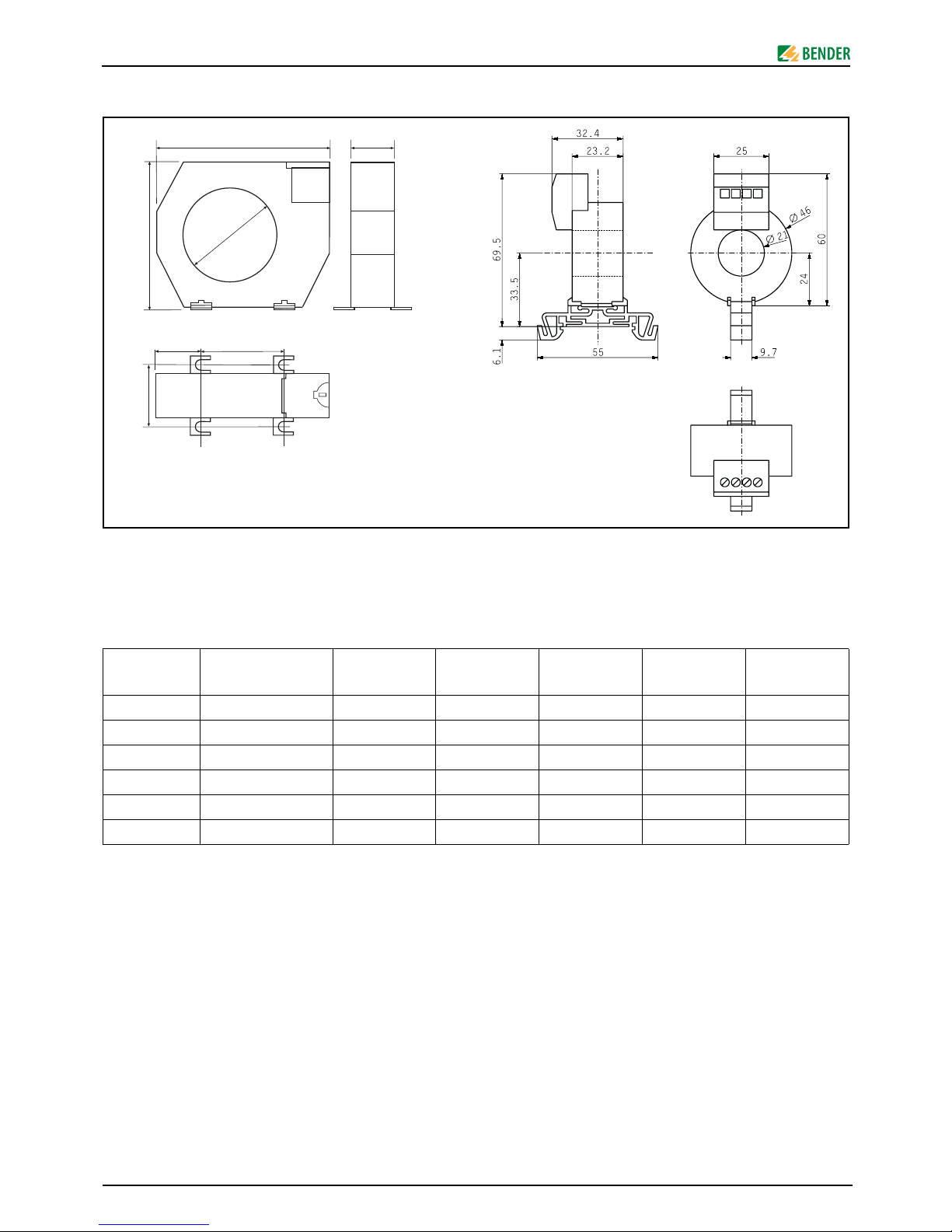
Dimension diagram
Fig. 1: Dimension diagram, the fixing lugs marked with an asterisk
are not provided for W1-35 version.
All dimensions given in mm.
Dimensions (mm), weight (g)
Connection
1. Install the measuring current transformer W1-35 ... W5-210
by connecting the two wires to the RCM or RCMS under
consideration of the technical data (in particular the cable
lengths).
2. Short-circuit the transformers which are not being used by
connecting the contacts k and l to PE. Depending on the
type of transformer, the designation of the connections
can also be S1 (instead of k) and S2 (instead of l).
3. Pass the conductors to be monitored through the measuring current transformer observing that:
– the PE must not be led through the transformer while
measurements of the residual current are carried out.
– the conductor is to be passed through the transformer
symmetrically at a right angle.
Maßbild
Abb. 1: Maßbild,
die mit * gekennzeichnete Laschen entfallen bei W1-35.
Alle Maße sind in mm angegeben.
Abmessungen (mm), Gewichte (g)
Anschluss
1. Schließen Sie die Messstromwandler W0-S20 ... W5-S210
mit zwei Anschlussdrähten an das RCM oder RCMS an.
Beachten Sie dabei die Angaben in den technischen Daten
(insbesondere die Leitungslängen).
2. Schließen Sie nicht benutzte Messstromwandler kurz. Verbinden Sie dazu die Kontakte k und l mit PE. Je nach Ausführung können die Wandleranschlüsse auch mit S1
(anstatt k) und S2 (anstatt l) gekennzeichnet sein.
3. Führen Sie die zu überwachenden Leiter durch den Messstromwandler. Beachten Sie dabei:
– Der PE darf bei der Differenzstrommessung nicht durch
den Messstromwandler geführt werden.
– Leiter möglichst symmetrisch und rechtwinklig durch
den Messstromwandler führen.
Typ
Typ e
ABCD
∅E
Gewicht
Weight
W0-S20 -- -- -- -- 21 70
W1-S35 100 79 26 48,5 35 140
W2-S70 130 110 32 66 70 185
W3-S105 170 146 38 94 105 425
W4-S140 220 196 48,5 123 140 590
W5-S210 299 284 69 161 210 1100
W1-S35 ... W5-S210
W0-S20
33
A
øE
B
46
C
D
ø 6,3
*
*
 Loading...