

Page 1
Quickstart
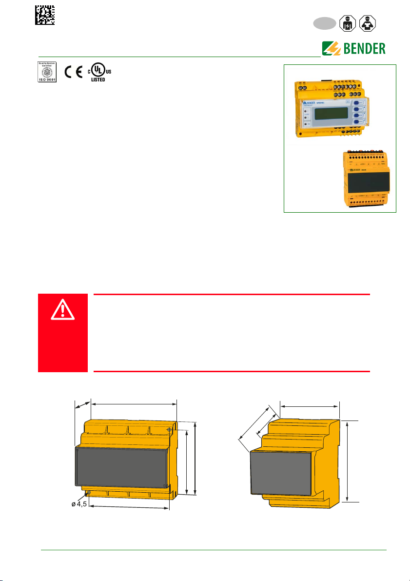
108
77
93
74
98
71,7
62,5
48,5
93,0
EN
VMD461 with CD440
Multifunctional voltage relay
Intended use
The multifunctional voltage monitoring relay VMD461 monitors frequencies, undervoltages and overvoltages in DC, AC and 3(N)AC systems. The
phase voltages and/or line-to-line voltages are measured as r.m.s. value
and are continuously shown on the device display. The measured value required to trigger the alarm relay is stored. The VMD461 features additional
measuring functions for:
ROCOF df/dt
Vector shift monitoring
Unbalance monitoring
Phase sequence monitoring
The corresponding ANSI codes for all available measuring functions are provided.
Configurable delay times allow considering special installation-specific properties (e.g. device-specific
start-up procedures). The VMD461 requires an external supply voltage.
The optional use of a CD440 coupling device extends the voltage range that can be monitored to DC/
3AC 1200 V or 1AC/3NAC 690 V. Any other use than that described in this manual is regarded as improper. The quickstart does not replace the manual of the device. Download: www.bender.de/manuals
Safety instruction
Danger of electrocution due to electric shock!
Touching live parts of the system carries the risk of:
An electric shock
Damage to the electrical installation
Destruction of the device
Before installing and connecting the device, make sure that the installation has
been de-energised. Observe the rules for working on electrical installations.
Dimension diagrams VMD461 (left) und CD440 (right) in mm
VMD461_D00314_00_Q_XXEN/10.2018
1
Page 2

Mounting on DIN rail and screw mounting
1.
2.
4.
„Klick“
3.
VMD461
CD440
2.
B98060008
M4
M4
98 mm
M4
3.
77 mm
4.
„Klick“
M4
Wiring
Depending on the application, connect the device according to the following wiring diagrams..
1.
100 mm
The VMD461 can be operated without a CD440 in appropriate power supply
systems (230/400 V).
Legend wiring diagrams
Element Funktion
A1, A2
L1, L2/DC+,
L3, N/DC-
Supply voltage U
Power supply connection
(see ordering details)
s
11, 12, 14 Connection to alarm relay K1
21, 22, 24 Connection to alarm relay K2
DG1/2,
D1, D2
Contact monitoring
DG1/2: GND
D1: Feedback signal contact to alarm relay K1
D2: Feedback signal contact to alarm relay K2
(feedback signal contacts optionally NC/NO/off)*
RTG, RT1
RTG: GND
RT1: Remote-trip input (optionally NC/NO/off )*
A, B Connection to communication interface BMS bus
R
on/off
* Explanation: NC (closed in non-operating state)
Activate or deactivate the terminating resistor of the BMS bus (120 Ω )
NO (open in non-operating state)
off (switched off)
Risk of unwanted device
failure!
Do not supply device from the
monitored system. Pay attention
to maximum supply voltage.
2
VMD461_D00314_00_Q_XXEN/10.2018
Page 3
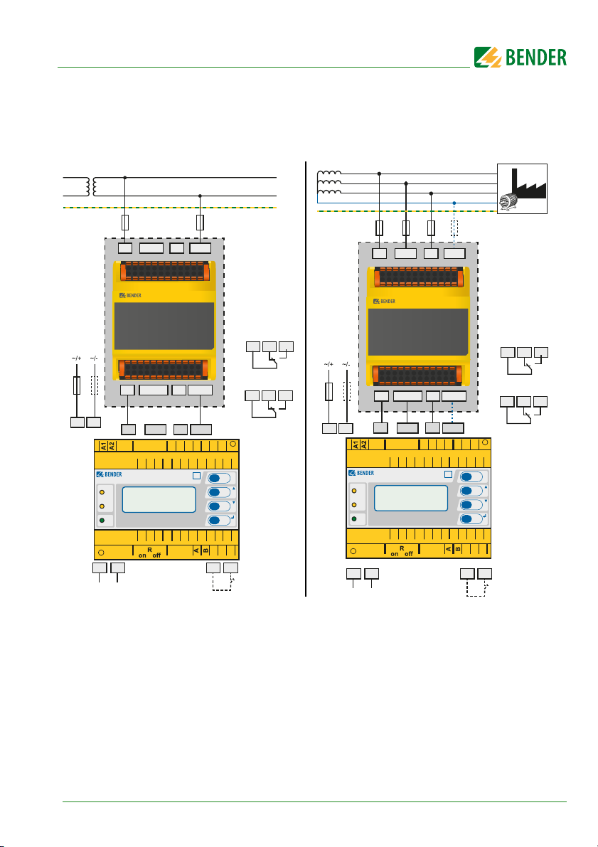
Unearthed system
*
CD440 optional
L1
L2
PE
U
n
L1
L2/DC+
L3 N/DC-
6 A
L1' L2'/DC+' L3'
11
21 241222
A B
RTGRT1
14
N'/DC-'
K1
K2
A1 A2
U
S
6 A
6 A
CD440
L1 L3 N/DC-L2/DC+
L1' L3' N'/DC-'L2'/DC+'
1112142122
24
L3
L2/DC+
L1
D2
D1
DG1/2
RTG
RT1
2
1
ON
ALARM
MENU
INFO
TEST
RESET
ESC
LINETRAXX®
VMD461
V
N/DC-
L1
L2/DC+L3N/DC-
6 A
AC 3(N)AC
L1
L2
L3
N
PE
6 A
L1
L2/DC+
L1 L3 N/DC-L2/DC+
CD440
6 A
L3 N/DC-
6 A 6 A
*
CD440 optional
VMD461_D00314_00_Q_XXEN/10.2018
L1
24
L3
L2/DC+
ESC
INFO
TEST
RESET
MENU
N/DC-
RT1
RTG
21 241222
11
K1
K2
14
S
LINETRAXX®
ALARM
L1' L3' N'/DC-'L2'/DC+'
L1' L2'/DC+' L3'
L1
VMD461
2
1
ON
N'/DC-'
L2/DC+L3N/DC-
1112142122
D2
D1
DG1/2
V
U
6 A
6 A
A1 A2
A B RTGRT1
3
Page 4

Earthed system
*
CD440 optional
L1' L2'/DC+' L3'
11
21 241222
A B
RTGRT1
14
N'/DC-'
K1
K2
A1 A2
U
S
6 A
6 A
CD440
L1 L3 N/DC-L2/DC+
L1' L3' N'/DC-'L2'/DC+'
L1
L2
L3
N
L1
L2/DC+
L3 N/DC-
6 A 6 A
6 A
PE
1112142122
24
L3
L2/DC+
L1
D2
D1
DG1/2
RTG
RT1
2
1
ON
ALARM
MENU
INFO
TEST
RESET
ESC
LINETRAXX®
VMD461
V
N/DC-
L1
L2/DC+L3N/DC-
*
CD440 optional
L1
N
PE
L1
L2/DC+
L3 N/DC-
6 A
L1' L2'/DC+' L3'
11
21 241222
A B RTGRT1
14
N'/DC-'
K1
K2
A1 A2
U
S
6 A
6 A
CD440
L1 L3 N/DC-L2/DC+
L1' L3' N'/DC-'L2'/DC+'
1112142122
24
L3
L2/DC+
L1
D2
D1
DG1/2
RTG
RT1
2
1
ON
ALARM
MENU
INFO
TEST
RESET
ESC
LINETRAXX®
VMD461
V
N/DC-
L1
L2/DC+
L3
N/DC-
AC 3(N)AC
4
VMD461_D00314_00_Q_XXEN/10.2018
Page 5

DC
*
CD440 optional
L+
L-
PE
L1
L2/DC+
L3 N/DC-
L1'
L2'/DC+' L3'
11
21 241222
A B
RTGRT1
14
N'/DC-'
K1
K2
CD440
L1 L3 N/DC-L2/DC+
L1' L3' N'/DC-'L2'/DC+'
1112142122
24
L3
L2/DC+
L1
D2
D1
DG1/2
N/DC-
RTG
RT1
2
1
ON
ALARM
MENU
INFO
TEST
RESET
ESC
LINETRAXX®
VMD461
V
L1
L2/DC+
L3
N/DC-
A1
A2
U
S
6 A
6 A
6 A
low : < 4 V DC
high : > 6 V DC
U
max
= 30 V DC
V1
Dx
GND
12 V
DC
Source
I < 5 mA
Open
Collector
DGx
µC
Relais
Kontakt
Dx: D1, D2, RT1
DGx: DG1/2, RTG
Q1
24 V
1
2
R1
Details regarding the digital
inputs (D1, D2, RT1)
VMD461_D00314_00_Q_XXEN/10.2018
5
Page 6

Initial commissioning
VMD461
V
LINETRAXX®
When commissioning the device for the first time you have to:
Select a language (English, German, French) (menu 4.2).
Set date and time (menu 4.3).
You can only change settings in the menus after the settings listed above have been carried out
.
The contrast of the LC display can be adjusted to any ambient brightness.
Select the contrast ratio from an infinite lo op display. Simultaneously press and hold
down the buttons "INFO" and "MENU" until the display text is clearly readable. After
reaching a black display, the contrast setting process starts again with a white display.
User interface
Legend
Power On LED, green;
Element
ALARM1
ALARM2
RESET
lights when the voltage supply is available and the device is in operation;
flashes when the device is being started or when an internal device error has occurred
Alarm LEDs, yellow: installation switched off
ON
Only ALARM 1 lights: alarm relay K1 has tripped
Only ALARM 2 lights: alarm relay K2 has tripped
ALARM 1 and ALARM 2 light: response value violation of voltage or frequency, df/dt, vec-
tor shift detection, unbalance, phase sequence, remote trip
ALARM 1 and ALARM2 flash: internal device error or error in contact monitoring
Backlit LC display
Standard display: Toggle between standard display and device information
INFO
Menu display: Exit the parameter setting menu
ESC
without saving; switch to the next higher
menu level
Standard display: Use the TEST button (< 1.5 s) to start a manual self test which triggers
TEST
both alarm relays (trigger test to check the switches/disconnectors). In addition, the
switch-off times are documented, .
Menu display: arrow-up button for parameter change and scrolling
Standard display: (> 1.5 s) Acknowledge fault messages from contact monitoring
Menu display: arrow-down button for parameter change/scrolling
6
VMD461_D00314_00_Q_XXEN/10.2018
Page 7

MENU
Standard
display
Info
display
Menu
display
ESC
INFO
Standard
display
Info
display
Menu
display
INFO
ESC
Alarm
display
MENU
MENUMENU
MENU
no alarm alarm
ESC
ESC
ESC MENU
2
ALARM
1
ON
2
ALARM
1
ON
2
ALARM
1
ON
2
ALARM
1
ON
Standard display: Toggle between standard, menu and alarm display
Menu display: button
Jump to setting parameter; save the changed parameters
Toggling between the individual displays
LEDs
The state of the VMD461 can be determined by means of the LEDs. The following table provides an overview of the possibilities.
LED Meaning LED Meaning Action
Normal operation mode:
VMD461_D00314_00_Q_XXEN/10.2018
device in operation, all the
measured values are within
the specified limits
Alarm, limit value of K1 and
K2 violated
Alarm, limit value of K2
violated
2
Alarm, limit value of
ALARM
K1 violated
1
ON
Error contact monitoring or internal error
2
Device starts
ALARM
1
(> 10 s): internal
ON
device error
You can toggle between the
different displays by using
the four device buttons. Depending on the type of display (standard display,
alarm display, menu display,
info display), the meaning
of the buttons is different.
The picture below illust rates
which button is to be
pressed for accessing the individual display. First, you
have to distinguish between an alarm condition
and no alarm condition..
Check switches/disconnectors * ;
in case of int. errors:
contact service
Wait (< 10 s)
Contact service
7
Page 8

Menu
1. Alarm/meas. values
4. System
3. Settings
5. Info
History
1. General
2. Voltage
(59/27)
U>>> (59.S3), t
off
U>> (59.S2), t
off
U> (59.S1), t
off
U
(on)max
, U
(on)min
U< (27.S1), t
off
U<< (27.S2), t
off
U<<< (27.S3), t
off
Delete history, Language, Clock, Password, Interface, Alarm addresses,TEST,
RESET, Test communication, External devices, Service, Factory settings
2. History
U
(1-N)
, U
(2-N)
, U
(3-N)
, U
(1-2)
, U
(2-3)
, U
(3-1)
, Unbalance, Phase sequence,
Frequency, df/dt (81R), Vect.sh.(78), Status, t
on1
, t
on2
, t
off total
Coupling, System type, U
(L-N)
, t
start-up
, Remote trip
3. Frequency(81)
f>>> (81>.S3), t
off
f>> (81>.S2), t
off
f> (81>.S1), t
off
f
(on)max
, f
(on)min
f< (81<.S1), t
off
f<< (81<.S2), t
off
f<<< (81<.S3), t
off
4. df/dt (81R)
Function, Resp.value, Hysteresis, Meas.window, t
off, ton
5. Vect.sh. (78)
Function, Resp.value, t
start-up
, t
on
7. Phase
sequence(47)
Function, Resp.value, Hysteresis, t
off
8. Relays
Relay mode, t
on
, Fault memory, Start alarm,
Device error, TEST, U>>> (59.S3), U>> (59.S2),
U> (59.S1), U< (27.S1), U<< (27.S2, U<<< (27.S3),
f>>> (81>.S3),f>> (81>.S2), f> (81>.S1), f< (81<.S1),
f<< (81<.S2), f<<< (81<.S3), df/dt (81R), Vect.sh. (78),
Unbalance, Phase sequence, Remote trip
9. Dig. input
Mode, t
start-up
Device type, Current date and time, BMS bus address, Software version
measurement technology, Software date measurement technology,
Software version display, Software date display, Manufacturer of the device,
Address of the manufacturer, Internet address of the manufacturer
6. Unbalance
(47)
Function, Phase sequence
© Bender GmbH & Co. KG
All rights reserved.
Reprinting only with permission of
the publisher.
Subject to change!
Photos: Bender Archiv
P.O. Box 1161 • 35301 Gruenberg • Germany
Londorfer Strasse 65 • 35305 Gruenberg • Germany
Tel.: +49 6401 807-0 • Fax: +49 6401 807-259
E-Mail: info@bender.de • www.bender.de
Bender GmbH & Co. KG
 Loading...