

Page 1
Manual
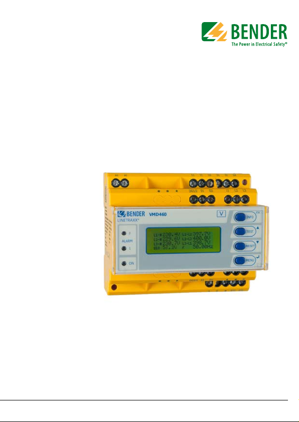
VMD460-NA
Network and system protection (NS protection) for monitoring
the power feed-in of power generation systems
Software version: D398 V1.1x
Display software version: D403 V2.2x
VMD460-NA_D00001_01_M_XXEN/08.2013
Page 2

Bender GmbH & Co. KG
Londorfer Str. 65 • 35305 Gruenberg • Germany
Postfach 1161 • 35301 Gruenberg • Germany
Tel.: +49 6401 807-0
Fax: +49 6401 807-259
E-Mail: info@bender-de.com
Web: http://www.bender-de.com
© Bender GmbH & Co. KG
All rights reserved.
Reprinting only with permission
of the publisher.
Subject to change!
Page 3

Table of Contents
1. How to use this documentation effectively ................................................ 7
1.1 How to use this manual ................................................................................. 7
1.2 Technical support: Service and support .................................................. 8
1.3 Workshops .......................................................................................................... 9
1.4 Delivery conditions, guarantee, warranty and liability .................... 10
2. Safety ................................................................................................................ 11
2.1 Intended use ................................................................................................... 11
2.2 Electrically skilled person ........................................................................... 11
2.3 General safety instructions ........................................................................ 12
3. Function ........................................................................................................... 13
3.1 Device features .............................................................................................. 13
3.2 Description of function ............................................................................... 14
3.2.1 Calculating the average value of overvoltage
(VDE-AR-N 4105, CEI 0-21, C10/11) ......................................................... 14
3.2.2 Self test, automatic ....................................................................................... 14
3.2.3 Manual self test .............................................................................................. 15
3.2.4 Remote-Trip (RTG / RT1) ............................................................................. 15
3.2.5 Malfunction and messages ........................................................................ 16
3.2.6 Delay times ton and toff ............................................................................. 17
3.2.7 Password protection .................................................................................... 17
3.2.8 Factory setting ............................................................................................... 17
3.2.9 Erasable history memory ............................................................................ 17
3.2.10 Passive islanding detection (df/dt) ......................................................... 18
VMD460-NA_D00001_01_M_XXEN/08.2013
3
Page 4

Table of Contents
4. Installation, connection and commissioning ........................................... 19
4.1 Unpacking ........................................................................................................ 19
4.2 Back-up fuses .................................................................................................. 19
4.3 Notes on mounting ...................................................................................... 20
4.4 Block diagram ................................................................................................. 20
4.5 Dimension diagram VMD460-NA ............................................................ 21
4.6 DIN rail mounting: ......................................................................................... 21
4.7 Screw mounting ............................................................................................ 21
4.8 Wiring diagram .............................................................................................. 22
4.8.1 VDE-AR-N 4105, BDEW, C10/11 ................................................................ 22
4.8.2 CEI 0-21 ............................................................................................................. 24
4.8.3 Details regarding the digital inputs (D1…D4, RT1) .......................... 27
4.9 Standards, selectable ................................................................................... 27
4.10 Commissioning .............................................................................................. 27
4.11 Trigger circuit test by the system erector ............................................. 28
5. Operation and configuration ...................................................................... 29
5.1 Getting to know the user interface ......................................................... 29
5.2 Various displays ............................................................................................. 30
5.2.1 Standard display ............................................................................................ 30
5.2.2 Info display ...................................................................................................... 31
5.2.3 Alarm display .................................................................................................. 31
5.2.4 Menu display ................................................................................................... 31
5.2.5 Toggling between the displays ................................................................ 32
5.3 INFO button ..................................................................................................... 33
5.4 Menu button ................................................................................................... 33
5.4.1 Alarm/meas. values ...................................................................................... 34
5.4.2 History ............................................................................................................... 35
5.4.3 Settings ............................................................................................................ 37
5.4.4 System ............................................................................................................... 38
4
VMD460-NA_D00001_01_M_XXEN/08.2013
Page 5

Table of Contents
5.4.5 Info ......................................................................................................................40
6. Maintenance ................................................................................................... 41
7. Selectable default settings ........................................................................... 43
7.1 VDE-AR-N 4105 .............................................................................................. 44
7.2 CEI 0-21 ............................................................................................................. 46
7.3 BDEW-guideline ............................................................................................. 49
7.4 C10/11 ............................................................................................................... 52
8. Technical data VMD460-NA ......................................................................... 55
8.1 Standards, approvals and certifications ................................................ 59
8.2 Ordering information .................................................................................. 59
INDEX ..................................................................................................................... 61
VMD460-NA_D00001_01_M_XXEN/08.2013
5
Page 6

Table of Contents
6
VMD460-NA_D00001_01_M_XXEN/08.2013
Page 7

1. How to use this documentation effectively
1. 1 How to use this manual
This operating manual will concern qualified experts in electrical engineering
and user of the product and must be kept ready for referencing in the immediate vicinity of the device.
In order to make it easier for you to find specific text passages or references in
this manual and for reasons of comprehensibility, important information is
emphasised by symbols. The meaning of these symbols is explained below:
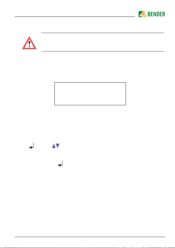
The warning symbol indicates a potential dangerous
situation that may result in bodily injury and/or damage
to property.
Observe the associated safety instructions.
Information intended to assist the user to make optimum
use of the product are marked with the Info symbol.
Although great care has been taken in the drafting of this operating manual,
it may nevertheless contain errors and mistakes.
The Bender Group cannot accept any liability for injury to persons or damage
to property resulting from errors or mistakes in this manual.
Each of the registered trademarks which appears in this document remains
the property of its owner.
VMD460-NA_D00001_01_M_XXEN/08.2013
7
Page 8

How to use this documentation effectively
1. 2 Technical support: Service and support
For commissioning and troubleshooting Bender offers you:
First level support
Technical support by phone or e-mail for all Bender products
Questions about special customer applications
Commissioning
Troubleshooting
Tel.: +49 6401 807-760*
Fax: +49 6401 807-259
only available in Germany: 0700BenderHelp (Tel. and Fax)
E-mail: support@bender-service.com
Repair service
Repair, calibration, update and replacement service for all Bender products
Repair, calibration, testing and analysing Bender products
Hardware and software update for Bender devices
Delivery of replacement devices for faulty or incorrectly delivered
Bender devices
Extended warranty for Bender devices with in-house repair service
resp. replacement devices at no extra cost
Tel.: +49 6401 807-780** (technical issues)
+49 6401 807-784**, -785** (commercial matters)
Fax: +49 6401 807-789
E-mail: repair@bender-service.com
Please send the devices for repair to the following address:
Bender GmbH, Repair Service,
Londorfer Strasse 65,
35305 Gruenberg,
Germany
8
VMD460-NA_D00001_01_M_XXEN/08.2013
Page 9

How to use this documentation effectively
Field service
On-site service for all Bender products
Commissioning, parameter setting, maintenance, troubleshooting for
Bender products
Analysis of the electrical installation in the building (power quality test,
EMC test, thermography)
Practical training courses for customers
Tel.: +49 6401 807-752**, -762 **(technical issues)
+49 6401 807-753** (commercial matters)
Fax: +49 6401 807-759
E mail: fieldservice@bender-service.com
Internet: www.bender-de.com
*Available from 7.00 a.m. to 8.00 p.m. on 365 days of the year (CET/UTC+1)
**Mo-Thu 7.00 a.m. - 8.00 p.m., Fr 7.00 a.m. - 13.00 p.m
1. 3 Workshops
Bender would be happy to provide training in respect of the use of the universal measuring device.
Current dates of training courses and workshops can be found
on the Internet at
http://www.bender-de.com/en/know-how/seminars.
VMD460-NA_D00001_01_M_XXEN/08.2013
9
Page 10

How to use this documentation effectively
1. 4 Delivery conditions, guarantee, warranty and liability
The conditions of sale and delivery set out by Bender apply.
For software products, the "Softwareklausel zur Überlassung von StandardSoftware als Teil von Lieferungen, Ergänzung und Änderung der Allgemeinen
Lieferbedingungen für Erzeugnisse und Leistungen der Elektroindustrie"
(software clause in respect of the licensing of standard software as part of deliveries, modifications and changes to general delivery conditions for products and services in the electrical industry) set out by the ZVEI (Zentralverband
Elektrotechnik- und Elektronikindustrie e.V. (German Electrical and Electronic
Manufacturers' Association) also applies.
Conditions of sale and delivery can be obtained from Bender in printed or
electronic format.
10
VMD460-NA_D00001_01_M_XXEN/08.2013
Page 11

2. Safety
2. 1 Intended use
The voltage and frequency monitoring relay VMD460-NA is used for system
and network protection (NS protection) of CHPs, wind, hydroelectric and photovoltaic systems feeding power into the grid.
If inadmissible voltage and frequency values occur on the supply side, the
VMD460-NA has the task of disconnecting the power generation system from
the distribution network by means of a coupling switch.
The voltage and frequency monitoring relay is to be installed and connected
directly at the central meter panel.
The VMD460-NA utilises a separate supply voltage connection.
Power generation systems with an output of > 6 kW
require a separate asymmetry monitoring.
2. 2 Electrically skilled person
Only electrically skilled persons are authorised to install and commission this
device. Electrically skilled persons are those who have the relevant education,
knowledge and experience, as well as knowledge of the relevant safety standards and who are able to perceive risks and to avoid hazards which electricity
can create when work activities are carried out on electrical installations. The
electrically skilled person is specially trained for carrying out work activities in
his specific working environment and has a thorough knowledge of the relevant standards and regulations. In Germany, an electrically skilled person
must meet the requirements of the accident prevention regulation BGV A3. In
other countries the applicable regulations have to be observed and followed.
VMD460-NA_D00001_01_M_XXEN/08.2013
11
Page 12

Safety
2. 3 General safety instructions
Bender devices are designed and built in accordance with the state of the art
and accepted rules in respect of technical safety. However, the use of such devices may introduce risks to the life and limb of the user or third parties and/
or result in damage to Bender devices or other property.
Danger of electric shock!
Touching live parts will cause danger of electric shoc k with fatal
consequences. All work activities on electrical installations as
well as installation activities, commissioning activities and
work activities with the device in operation may only be carried
out by electrically skilled persons!
Only use Bender equipment:
– as intended
– in perfect working order
– in compliance with the accident prevention regulations and guide-
lines applicable at the location of use
Eliminate all faults immediately which may endanger safety.
Do not make any unauthorised changes and only use replacement
parts and optional accessories purchased from or recommended by
the manufacturer of the equipment. Failure to observe this requirement can result in fire, electric shock and injury.
If the device is overloaded by overvoltage or a short-circuit current
load, it must be checked and replaced if necessary.
If the device is being used in a location outside the Federal Republic of
Germany, the applicable local standards and regulations must be complied with. European standard EN 50110 can be used as a guide.
Device-specific safety information
After commissioning, the essential settings of the
VMD460-NA have to be protected against unauthorised
changes by a password.
If the password protection is not used, the device has
to be sealed.
12
VMD460-NA_D00001_01_M_XXEN/08.2013
Page 13

3. Function
3.1 Device features
Straightforward commissioning by means of default basic programs
for national standards and regulations
Single-fault safety
Monitoring of the connected coupling switches
Islanding detection df/dt (ROCOF)
Service Interface RS-485 (software update)
Test function with determination of the disconnection time
Test button for the trigger circuit
The last 300 distribution network faults can be recalled with
time stamp/real-time clock
Continuous monitoring of the phase voltage and line-to-line voltage
Special connection conditions after an infringement of a limit value
Language selection (German, English, Italian)
Backlit graphics LC display
Password protection for device setting
Remote shutdown via ripple control signal receiver
Sealable enclosure
VMD460-NA_D00001_01_M_XXEN/08.2013
13
Page 14

Function
3.2 Description of function
The power generation system is only allowed to connect to the public grid
when the country-specific connection conditions are met. Mains voltage and
mains frequency must be within the defined tolerance range.
The devices utilise several separately adjustable measuring channels for:
Voltage drop protection U <, U<<
Rise-in-voltage protection U >>, U10> / U> (depending on standard)
Frequency decrease protection f <, f<<
Frequency increase protection f >, f>>
This satisfies the requirements for static and dynamic network monitoring.
In case of infringements of a limit value or a remote trip signal, the relay K1
(and K2, if necessary) switch and the alarm LEDs light. Reconnection to the
grid is carried out when the national connection conditions to the grid are
met. Pressing the test button ensures that the relays are checked and the required test (trigger test) of the relays K1 and K2 is carried out.
3.2.1 Calculating the average value of overvoltage
(VDE-AR-N 4105, CEI 0-21, C10/11)
The overvoltage U10 is determined by averaging the last 10-minute measuring interval. Always the highest 10-minute average value value U10> of each
of the three voltages monitored between L1-N, L2-N, L3-N will be indicated.
3.2.2 Self test, automatic
The device runs a continuous self test during which internal malfunctions are
detected and shown on the display as error codes. The alarm relays are not
switched during this test.
14
VMD460-NA_D00001_01_M_XXEN/08.2013
Page 15

Function
3.2.3 Manual self test
The self test cannot be started unless the power generation system has been
started by the VMD460-NA (both alarm LEDs off) and the contact monitoring
is installed and activated.
Start of the manual self test:
1. Press the test button in the standard display (> 1.5 s) or
2. select "TEST" from the menu display
The alarm relays K1 and K2 switch during the self test and open resp. close the
contacts 11/12/14 and 21/22/24.
The self test continues to run until the defined disconnection time t
undervoltage condition has elapsed.
Both coupling switches are switched off during the self
test.
at
off
During the self test, the times are measured until the switching command for
the coupling switches (t
(t
) trip. These periods are automatically indicated by alarm displays
off (TOTAL)
off (DEVICE)
for the measuring channels 15 (t
available in the "Alarm/meas. value" menu.
) is activated or until the coupling switches
off (TOTAL)
) and 16 (t
off (DEVICE)
). They are also
3.2.4 Remote-Trip (RTG / RT1)
The activation of this function is optional and can be used to separate the
power generation system from the supply network remotely via an external
contact. After activating the remote control, the coupling switch will be
switched after ≤ 50 ms.
This function can be deactivated in the "Settings / General / Remote Trip = off"
menu, if not required.
VMD460-NA_D00001_01_M_XXEN/08.2013
15
Page 16

Function
3.2.5 Malfunction and messages
In case of malfunctions or messages, the power
generation system will be separated from the supply
network.
In the case of an internal malfunction or an error in the operation of the coupling switches, both alarm LEDs will flash. The error code or the message in
plain text is indicated on the display.
If several faults or messages occur simultaneously, they will be displayed alternately at four-second-intervals.
In the case of an internal error, make a note of the error code "xx" and contact
the Bender Service.
Code/
Message
1…20
contact
monit. K1
contact
monit. K2
16
LED Meaning Remedy
Both LEDs
flash
Both LEDs
flash
Internal error
Error:
Contact
monitoring
K1
Error:
Contact
monitoring
K2
Make a note from the error
code "xx“ and contact the
Bender Service.
After rectifying the the fault
at the coupling switch/main
switch (e.g. manual connection of the backup switch),
the fault is automatically
cleared. Should, however, a
fault have occurred three
times within 30 seconds, normal operation must be
started again after fault rectification by pressing the
"RESET" button (in the standard display).
VMD460-NA_D00001_01_M_XXEN/08.2013
Page 17

Function
Code/
Message
23
Remote
trip
Enter
norm
3.2.6 Delay times t
Delay time for connection t
When all voltage and frequency values measured, meet the conditions for
connection during the delay time for connection, the alarm LEDs will go out
and the alarm relays will switch.
Response delay t
Minimum period for an error to exist until the alarm relays will switch.
LED Meaning Remedy
Both LEDs
flash
Both LEDs
light continuosly
Both LEDs
light continuosly
off
Internal error
Remote trip
active
No norm
selected
and t
on
off
on
Make a note from the error
code "xx“ and contact the
Bender Service.
Activate RTG/RT1 or deactivate the input via the menu
(off)
Select the application norm
from the menu.
3.2.7 Password protection
By default, the password protection is deactivated (off).
3.2.8 Factory setting
After activating the factory setting, all previously changed settings are reset to
delivery status.
3.2.9 Erasable history memory
The device utilises a history memory for failsafe storing of up to 300 data
records (date, time, channel, event code, measured value).
VMD460-NA_D00001_01_M_XXEN/08.2013
17
Page 18

Function
3.2.10 Passive islanding detection (df/dt)
The VMD460-NA uses a passive method for islanding detection (three-phase
voltage and frequency monitoring).
df/dt
The monitoring of the rate of change of frequency "ROCOF" (df/dt) is an
islanding detection function.
If a section of the network is disconnected by the energy provider, it may happen that the power generation systems located in this section unintentionally
feed this section of the network.
Underfrequency and overfrequency monitoring might not be sufficient to detect this dangerous, uncontrollable state, since the generators try to keep the
frequency at the nominal frequency level.
Due to the unbalance between generated and consumed energy, however,
the frequency fluctuates around the nominal frequency. If this happens at a
certain minimum speed, this is an indication of islanding, hence the power
generation system will be disconnected by the VMD460-NA.
As soon as the rate of change of frequency is below the response value
hysteresis and t
nected.
has expired, the power generation system will be recon-
on
t
off
Response delay: the time during which a limit value
(df/dt) must be violated until the power generation
system is disconnected by the VMD460-NA.
t
on
Delay time, if df/dt disconnected the system.
Measuring window Period of time used to calculate the average of the fre-
quency changes. The bigger the measuring window is
selected the less sensitive will the df/dt function be.
18
VMD460-NA_D00001_01_M_XXEN/08.2013
Page 19

4. Installation, connection and commissioning
Danger of electric shock!
Make sure that the installation area is disconnected
from any electrical source .
Consider the data on the rated voltage and supply
voltage as specified in the technical data!
4.1 Unpacking
Unpack all the parts supplied with the system. Avoid sharp-edged tools
that may damage the content of the packaging.
Compare your order with our delivery note to check that you have
received all products in full. The article numbers and type designation
printed on the nameplates provide an easy means of uniquely identifying each device.
Check all parts supplied for any evidence of damage in transit.
Equipment damaged in transit must not be used. If a device has sus-
tained damage, please contact Bender. Details of who to contact are
indicated on the delivery documents.
When storing the devices in an environment where the temperature is
wintry and cold:
Leave the devices to stand for 3 to 4 hours at room temperature before
connecting the power supply. When the devices are moved from a cold
to a warm environment, condensation will be evident on all parts.
Putting damp devices into operation risks damaging electrical components and there is a danger of electric shock on contact.
4.2 Back-up fuses
Equip the supply voltage of all system components with fuses. IEC 60364-4-43
requires protective devices to be used to protect the component in the event
of a short circuit. We recommend the use of 6 A fuses.
VMD460-NA_D00001_01_M_XXEN/08.2013
19
Page 20
Installation, connection and commissioning
4.3 Notes on mounting
Danger of electric shock!
Make sure that the installation area is disconnected
from any electrical source .
Consider the data on the rated voltage and supply
voltage as specified in the technical data!
The length of the connecting cable of the device
connections DG1/2, D1, D2, DG3/4, D3, D4, RTG and
RT1 is to be limited to 3 m.
To ensure the VMD460-NA's functionality aft er a power
failure, it is recommended to use an external UPS.
The devices are suitable for the following types of installation:
Standard distribution panels according to DIN 43871 or DIN rail mount-
ing according to IEC 60715
Screw mounting using M4 screws
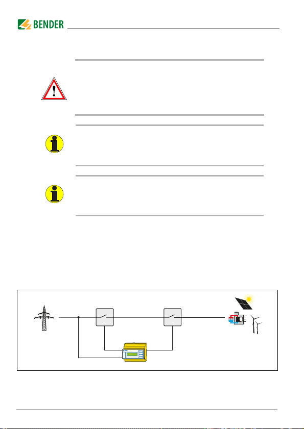
4.4 Block diagram
Coupling switch
Public grid
VMD460
Coupling switch
Power generation system
Fig. 4.1: Block diagram of a central NS protection with coupling switches
20
VMD460-NA_D00001_01_M_XXEN/08.2013
G
Page 21

Installation, connection and commissioning
4.5 Dimension diagram VMD460-NA
All dimensions in mm
Fig. 4.2: Dimension diagram and drawing for screw fixing
4.6 DIN rail mounting:
Snap the rear mounting clip of the device into place in such a way that a safe
and tight fit is ensured.
4.7 Screw mounting
1. Use the tool to move the rear mounting clips (a second. mounting clip
required, see ordering information) to a position that it projects
beyond the enclosure.
2. Then fix the device using two M4 screws.
VMD460-NA_D00001_01_M_XXEN/08.2013
21
Page 22

Installation, connection and commissioning
12
3
4
5
6
7
4.8 Wiring diagram
Connect the device according to the wiring diagram depending on the applicable standard.
4.8.1 VDE-AR-N 4105, BDEW, C10/11
Coupling switch 1 Coupling switch 2
L1
L2
L3
N
U
S
6 A
6 A
A1
A2 L1 L2 L3
6 A 6 A
6 A
DG1/2
D1
11 21
14N
D2
2412 22
Power
generation
system
K1 K2
LINETRAXX®
A B RTGRT1D4D3
VMD460
1112142122
DG1/2
DG3/4
DG3/4
24
L3L2L1
D2
D1
V
D4ND3
RTG
RT1
Fig. 4.3: Wiring diagram VMD460-NA (VDE-AR-N-4105, BDEW, C10/11)
22
VMD460-NA_D00001_01_M_XXEN/08.2013
Page 23

Installation, connection and commissioning
Key
No. Element Function
A1, A2
1
L1, L2, L3, N Power supply connection
2
K1, K2 Relay connections
3
DG1/2,
D1, D2
4
RTG, RT1
5
A, B Service interface
6
R
on/off
7
DG3/4, D3, D4not to be used in accordance with VDE-AR-N 4105,
* Explanation: NC (in non-operating state closed)
Supply voltage U
Contact monitoring coupling switch
DG1/2: GND
D1: feedback signal contact K1
D2: feedback signal contact K2
(feedback signal contacts optionally NC/NO/off)*
RTG: GND
RT1: Remote trip input (optionally NC/NO/off))*
Activate or deactivate the terminating resistor of the
service interface (120
BDEW, C10/11
NO (in non-operating state open)
off (switched off)
(see ordering information)
s
Ω )
Single-fault safety
In o rder to en sure s ingl e-fault safe ty, t he VDE -AR- N 410 5 has t o be r ealised for
the power generation system. A single fault in the actuation circuit must not
prevent a disconnection of the power generating system from the grid.
The monitoring circuit for grid disconnection of power generation systems is
to be installed at the point of supply. The relays used K1 and K2 are to be connected according to the wiring diagram.
Use the contact monitoring function to prevent the
sticking of contacts!
VMD460-NA_D00001_01_M_XXEN/08.2013
23
Page 24

4.8.2 CEI 0-21
12 4
3
6
7
8
5
Installation, connection and commissioning
LINETRAXX®
Backup
< U
VMD460
D2
Coupling switch 1
DG1/2
1112142122
D1
DG1/2
V
D1
11 21
K1 K2
24
L3L2L1
D2
14N
L1
L2
L3
N
U
S
6 A 6 A
A1
A2 L1 L2 L3
DG1/2
6 A 6 A 6 A
D4ND3
A B RTGRT1D4D3
DG3/4
DG3/4
RT1
RTG
Power
generation
system
2412 22
24
Fig. 4.4: Wiring diagram VMD460-NA (CEI 0-21)
VMD460-NA_D00001_01_M_XXEN/08.2013
Page 25

Installation, connection and commissioning
Key
No. Element Function
A1, A2
1
L1, L2, L3, N Power supply connection
2
DG1/2,
D1, D2
3
K1, K2 Relay connections
4
DG3/4,
D3, D4
5
RTG, RT1
6
A, B Service interface
7
R
on/off
8
* Explanation: NC (in non-operating state closed)
Supply voltage U
Contact monitoring coupling switch
DG1/2: GND
D1: feedback signal contact K1
D2: feedback signal contact K2 (Backup)
(optionally NC/NO/off ) *
Digital inputs (external monitoring)
DG3/4: GND
D3: Local control (CEI 0-21 8.6.2.1.1)**
D4: External signal (CEI 0-21 8.6.2.1.2)**
(optionally NC/NO/off )*
RTG: GND
RT1: Remote trip input (optionally NC/NO/off)*
Activate or deactivate the terminating resistor of the
service interface (120
NO (in non-operating state open)
off (switched off)
(see ordering information)
s
Ω )
** For evaluation of the inputs D3 and D4, the mode has to be set accordingly in
the menu:
VMD460-NA_D00001_01_M_XXEN/08.2013
25
Page 26

Installation, connection and commissioning
Example for N/O:
Connection D3, menu: „local“ (D4 will not be evaluated)
D3:
local control
open 49.5…50.5 0.1 s 81.S1
closed 47.5…51.5 0.1 s 81.S2
Example for N/O:
Connection D4, menu: „extern“ (D3 will not be evaluated)
D4:
external signal
open 49.5…50.5 0.1 s 81.S1
closed 47.5…51.5 4 s; 1 s 81.S2
In the case of a failure of the coupling switch 1 (K1), the contact
monitoring function will cause the backup relays to switch (K 2).
f [Hz]
f [Hz]
Disconnection
time
Disconnection
time
Norm CEI0-21
Norm CEI0-21
26
VMD460-NA_D00001_01_M_XXEN/08.2013
Page 27

Installation, connection and commissioning
4.8.3 Details regarding the digital inputs (D1…D4, RT1)
low : < 4 V DC
high : > 6 V DC
U
= 30 V DC
max
1
V1
24
2
DC
Source
Dx: D1, D2, D3, D4, RT1
DGx: DG1/2, DG3/4, RTG
Q1
Open
Collector
Relais
Kontakt
I < 5 mA
Dx
DGx
GND
Fig. 4.5: Block diagram (simplified representation)
4.9 Standards, selectable
The VMD460-NA includes the following standards:
VDE-AR-N 4105
CEI 0-21
BDEW
C10/11
Menu: "Settings" --> "General" --> "Norm".
4.10 Commissioning
Danger of electric shock!
Improper connection can lead to injury to persons and damage
to the device!
Prior to commissioning make sure that the device is properly
connected!
12V
R1
D1
µC
VMD460-NA_D00001_01_M_XXEN/08.2013
27
Page 28

Installation, connection and commissioning
Initial commissioning
When commissioning the device for the first time
Select a language (English, German, Italian).
Select a standard (VDE-AR-N 4105, CEI 0-21, BDEW, C10/11).
In addition, you have to set the date and the time.
You can only change settings in the menus after settings listed above have
been carried out.
The contrast of the LC display can be adjusted to any
ambient brightness.
Select the contrast ratio from an infinite loop display. After
reaching a black display, the contrast setting process starts
again with a white display. Simultaneously press and hold
down the buttons "INFO" and "MENU" until the display text is
clearly readable.
When switching to another application standard, the
associated factory settings will be loaded.
Existing user-defined settings will not be saved when
switching from one standard to another.
4.11 Trigger circuit test by the system erector
During commissioning, the system erector has to check the correct function
of the trigger circuit NS protection/coupling switch, as illustrated in the wiring
diagram in this operating manual, consisting of K1/K2 and coupling switch 1/
coupling switch 2.
Press the test button to activate the coupling switch.
Successful activation must be visualised by the coupling switch.
Contact monitoring of the coupling switch (optional, depending on
the standard)
Note the information about recurrent tests on page 41.
28
VMD460-NA_D00001_01_M_XXEN/08.2013
Page 29

5. Operation and configuration
1
2
3
4
5
6
7
5.1 Getting to know the user interface
LINETRAXX®
Key
No. Element Function
Power On LED, green;
ON
1
ALARM1
ALARM2
2
3
lights when the power supply is available and the device is
in operation;
flashes in case of system fault alarm (external watchdog)
Generation system disconnected:
Both LEDs light (yellow) in the case of limit value violation
and
of voltage, frequency, remote disconnection df/dt
(optional), asymmetry (optional);
Both LEDs flash (yellow) in the case of an internal device
error or a contact monitoring fault;
Only ALARM 1 lights: Delay time for connection t
Backlit LC display
VMD460-NA_D00001_01_M_XXEN/08.2013
VMD460
V
active
on
29
Page 30

Operation and configuration
L1-N 229.9V L1-L2 397.2V
L2-N 229.5V L2-L3 401.9V
L3-N 232.9V L3-L1 400.1V
U10 57.3V f 50.00Hz
Standard display: Toggling between standard display and
Info
device information
ESC
4
5
RESET Standard display: (> 1.5 s) Acknowledgement of fault
6
MENU
7
Menu display: To exit the parameter setting menu without
storing; to go to the next higher menu level
Standard display: A manual test is carried out using the
TEST
test button (> 1.5 s), during which both alarm relays are
triggered (trigger test for testing the coupling switches). In
addition, fault simulation will be carried out (disconnection
time documented)
Menu display: Arrow up button for parameter change and
scrolling
messages from contact monitoring
Menu display: Arrow down button for parameter change/
scrolling
Standard display: Toggling between standard, menu and
alarm display
Menu display: button
Jump to parameter settings; saving the changed parameters
5.2 Various displays
5.2.1 Standard display
In the standard display, phase voltages, line conductor voltages, the maximum 10-minute average value (depending on standard) and the frequency
are indicated on the display.
30
Fig. 5.1: Standard display
VMD460-NA_D00001_01_M_XXEN/08.2013
Page 31

Operation and configuration
VMD460-NA
22.02.13 12:34
Software: Dxxx
Date:18.02.13
ALARM 2/3
Undervoltage
U
(N-1)
: 180.3V
Addr.:1 Chan.:1
Exit
1. Alarm/meas. values
2. History
3. Settings
5.2.2 Info display
Device-specific information is available in the info display.
Fig. 5.2: Info display
For detailed information refer to page 33.
5.2.3 Alarm display
Type and source of alarms are indicated on the alarm display in plain text format.
Fig. 5.3: Al arm displ ay
Explanation: In the example above, the second message of three is being indicated (2/3). The address "Addr" currently is of no significance. The alarm is
outputted on measuring channel 1 and can be accessed via channel number 1
in the "Alarm/meas. values" menu.
5.2.4 Menu display
Alarms, currently measured values as well as the history memory can be called
up via the menu display. Settings can also be changed in this display.
VMD460-NA_D00001_01_M_XXEN/08.2013
Fig. 5. 4: Menu display
31
Page 32

Operation and configuration
5.2.5 Toggling between the displays
You can toggle between the different displays by using the four device buttons. Depending on the type of display (standard display, alarm display, menu
display, info display), the meaning of the buttons is different. The picture below illustrates which button is to be pressed for accessing the individual display. First, it is necessary to determine whether an alarm exists or not.
Without alarm With alarm
ESC
info
display
MENU
standard
dispaly
ESC
menu
display
INFO
MENU
ESC
ESC
info
display
MENU
standard
display
MENU
alarm
display
menu
display
Fig. 5.5: Toggling between the displays (with or without alarm)
32
VMD460-NA_D00001_01_M_XXEN/08.2013
INFO
ESC
MENU
Page 33

Operation and configuration
5.3 INFO button
Dev ice i nfor matio n in c lear t ext f ormat (I nfo d ispl ay) ca n be call ed up with the
"INFO" button. For this purpose press the "INFO" button in the standard display once. Scroll through the individual lines using the arrow buttons :
Device type
Current date, current time
Address BMS-Bus
Software version (measurement technique)
Date of software (measurement technique)
Software version (display)
Date of software (display)
Manufacturer of the device
Address of the manufacturer
Internet address of the manufacturer
Return to standard display via "ESC" resp. .
5.4 Menu button
Toggling between the standard, alarm and menu display (see page 32).
The individual entries in the menu display can be accessed using the arrow
buttons :
The menu display provides the following submenus
Exit
1. Alarm/meas. values
2. History
3. Settings
4. System
5. Info
VMD460-NA_D00001_01_M_XXEN/08.2013
33
Page 34

Operation and configuration
5.4.1 Alarm/meas. values
For detailed information about the value, select the "Alarm/meas. values"
menu item (select the menu item using ).
Select the individual entries by means of the buttons.
Exit
1. U(1-N): Value
2. U(2-N): Value
3. U(3-N): Value
4. U10: Value
5. U(1-2): Value
6. U(2-3): Value
7. U(3-1): Value
8. Frequency: Value
9. df/dt: Value
10. Status*
11. T(ON) : Value
12. Asymmetry: Value
13. Vect. shift**: Value
14. Phase sequ.: Value
15. T(OFF)TOTAL: Value
16. T(OFF)DEVICE: Value
For each of these entries you can check whether an alarm exists or not:
= no alarm
= alarm
* Measuring channel 10: The text depends on the existing message. If several
messages exist, the individual messages appear automatically on the display
every four seconds.
34
VMD460-NA_D00001_01_M_XXEN/08.2013
Page 35

Operation and configuration
History No. 297
Start: 01.02.13 / 15:57:00
Quit:
End: 01.02.13 / 16:07:03
Measuring channel 15: Indicates the total time passed during the self test
between the simulation of 0 V on L1 to the disconnection of coupling
switch 1.
Measuring channel 16: Indicates the total time passed during the self test
between the simulation of 0 V on L1 to the disconnection command for
coupling switch 1.
** not used
5.4.2 History
The fail-safe history memory stores up to 300 events (alarms, tests) with information about alarms and acknowledgements and the time the event happened. If the history memory is full, the oldest entry will be deleted in the
event of an alarm to create space for the new entry (FIFO principle).
For details about erasing the entire history memory manually, refer to
"Chapter 5.4.4 System" on page 38.
Fig. 5. 6: Histor y (overview)
Key
Line 1: Event number
Line 2: Event start: Date/time
Line 3: Acknowledgement of the event: Date/time
Line 4: Event end: Date/time
Possibilities:
1. If you are searching for an event that occurred at a specific time, use the
arrow buttons to scroll to the required entry.
2. Call up details: Use the button to call up the current history memory
entry.
VMD460-NA_D00001_01_M_XXEN/08.2013
35
Page 36

Operation and configuration
History No. 297
Undervoltage
Min. 21 V/max.198 V
Addr.:2 Chan.:1
Fig. 5.7: History (detail)
Key
Line 1: Data record number
Line 2: Alarm status and alarm text (e.g. undervoltage, transformer error,…)
= no alarm
= alarm, fault
Line 3: Minimum and maximum measured value after the occurrence
of an alarm
Line 4: RS-485 address and measuring channel of the device sending
the message
36
VMD460-NA_D00001_01_M_XXEN/08.2013
Page 37
Operation and configuration
Please enter
password:
0 0 0
5.4.3 Settings
Response values for NS protection may only be changed in
consultation with the network operator!
Settings can be password protected. If the password is activated (enabled), all
settings continue to be displayed. When an attempt is made to change settings, the password entry screen appears automatically:
Once a valid password has been entered, access will be granted to settings in
all menus (except the Service menu) until menu mode is exited.
If you can't remember your password, contact the Bender Service.
In principle, all preset response values can be changed, if this should be necessary. The values can be changed in the third level of the menu (column
"twice ") using .
There are two different ways to exit the setting menu:
Save and exit: „ “
Exit without saving: "ESC"
The menu structures in the settings contain different entries for each individual standard. These are listed in detail in "Chapter 7. Selectable default set-
tings".
VMD460-NA_D00001_01_M_XXEN/08.2013
37
Page 38

Operation and configuration
5.4.4 System
The following table gives an overview of the menu structure. The values can
be changed in the third level of the menu (column "twice ") using .
There are two different ways to exit the system menu:
Save and exit: „ “
Exit without saving: "ESC"
Menu: System
1. History Exit
2. Language Exit
3. Clock Exit
38
once twice
Delete
Delete
Cancel
English
English
Italiano
Format
Date
Time
CEST
d.m.y
m-d-y
Toggling between the date elements
Toggling between hour and
minute with
auto
off
VMD460-NA_D00001_01_M_XXEN/08.2013
Page 39

Operation and configuration
Menu: System
4. Password Exit
5. Interface
6. Alarm addresses Exit
7. TEST Cancel
8. RESET Cancel
9. Test
communication
10. External devices Exit
11. Factory setting Cancel
once twice
Password
Status
Exit
Address
Address xxx
TEST
RESET
Exit
1. Chan.
List of the
devices connected
Factory settings
* * *
Toggling between positions with
off
on
1…90
1: MASTER
2…90: Slave
1…150: off/on
Test will be carried out
Reset will be carried out
Channel (1…12)
1: Own address
2…150: External devices
Restore factory settings
VMD460-NA_D00001_01_M_XXEN/08.2013
39
Page 40

Operation and configuration
5.4.5 Info
The following table gives an overview of the information to be called up.
Scroll through the individual lines using the arrow buttons :
Device type
Current date, current time
Address BMS-Bus
Software version (measurement technique)
Date of software (measurement technique)
Software version (display)
Date of software (display)
Manufacturer of the device
Address of the manufacturer
Internet address of the manufacturer
40
VMD460-NA_D00001_01_M_XXEN/08.2013
Page 41

6. Maintenance
Repeat test of the trigger circuit by the system operator
The system operator must ensure that the equipment required for parallel
operation with the low-voltage network is always in proper technical condition. To this end, it is required to have an electrically skilled person check the
protective devices for proper functioning at regular intervals. This requirement is deemed to be satisfied for normal and environmental conditions if the
test intervals mentioned in BGV A3 are adhered to. The repeat test shall include at least the following:
Check of the environmental conditions (pollution, mechanical or isola-
tion damage).
A tripping control of the coupling switch.
Press the "TEST" button to trigger the coupling switch.
Tripping must be visualised by the coupling switch.
The trigger circuit NS protection/coupling switch, in the wiring diagram of this
operating manual consisting of K1/K2 and coupling switch 1/coupling switch
2, separates the power generation system from the public low-voltage grid.
By checking the trigger circuit regularly, sticking of the contactors can be
detected at an early stage.
VMD460-NA_D00001_01_M_XXEN/08.2013
41
Page 42

Maintenance
42
VMD460-NA_D00001_01_M_XXEN/08.2013
Page 43

7. Selectable default settings
Response values for NS protection may only be changed in
consultation with the system operator!
The following standards are implemented in the factory settings of the
VMD460-NA:
VDE-AR-N 4105
CEI 0-21
BDEW guideline
C10/11
In preparation
– G59/2
– G83/2
– DIN V VDE V 0126-1-1
The following tables give an overview about the menu structure for each preset standard. The values can be changed in the third level of the menu
(column "twice ") using .
The respective menu item can be exited with
ESC (= without saving changed parameters)
(= saving the changed parameters)
When switching to another application standard, the
associated factory settings will be loaded.
Existing user-defined settings will not be saved when
switching from one standard to another.
VMD460-NA_D00001_01_M_XXEN/08.2013
43
Page 44

7.1 VDE-AR-N 4105
4105 Menu :
Settings
Exit
General Exit
Volt age Exit
once twice
norm
coupling
U(L-N)
U(L-L)
t SHORT INT.
t (ON) SHORT INT. 1 s…60 min 5 s
t (ON) NORMAL 1 s…60 min 60 s
Remote Trip
U>> off/100…130 % 115 %
U> off/100…130 % 110 %
U (ON) MAX off/100…130 % 110 %
U (ON) MIN off/1…100 % 85 %
U< off/1…100% 80 %
CEI021
4105
1 AC
3N AC
3 AC
50…250 V
87…433 V
1…300 s
6…60.0 min
N/C
N/O
off
Selectable default settings
Fac tor y
setting
3N AC
U(L-N) 230 V
3 s
off
44
VMD460-NA_D00001_01_M_XXEN/08.2013
Page 45

Selectable default settings
4105 Menu :
Settings
Frequ ency Exit
df/dt Exit
Asymmetry Exit
Relay Exit
once twice
f> off/50.00…65.00 Hz 51.50 Hz
f (ON) MAX off/50.00…65.00 Hz 50.05 Hz
f (ON) MIN off/45.00…60.00 Hz 47.50 Hz
f< off/45.00…60.00 Hz 47.50 Hz
Mode off/on off
Resp. value 0.1…9.9 Hz/s 1.0 Hz/s
Hysteresis 1.0…50.0 % 20.0 %
Meas. window 0.05…1.0 s 200 ms
T (OFF) 0.04…30.0 s 100 ms
T (ON) 1 s…60 min 60 s
Mode off/on off
Resp. value 1.0…50.0 % 5.0 %
Hysteresis 1.0…50.0 % 20.0 %
T (OFF) 0.04…30.0 s 100 ms
Relay mode
N/C
N/O
Fac tor y
setting
K1: N/C
K2: N/C
VMD460-NA_D00001_01_M_XXEN/08.2013
45
Page 46

Selectable default settings
4105 Menu :
Settings
once twice
Digital Input Exit
Relay mode N/C; N/O; off
* not used in VDE-AR-N 4105
7.2 CEI 0-21
CEI 0-21 menu:
Settings
Exit
General Exit
1)
Analysis of digital input D4 (external signal)
2)
Analysis of digital input D3 (local control)
once twice
norm
coupling
U(L-N)
U(L-L)
Mode
T (ON) 0.04…30.0 s 70 ms
Remote trip N/C; N/O; off N/C
CEI021, 4105, BDEW,
C10/11
3N AC
1 AC
3 AC
50…250 V
87…433 V
1)
2)
off/extern
/local
Fac tor y
setting
D1: N/C
D2: N/C
D3: off*
D4: off*
Fact ory
setting
3N AC
U(L-N) 230 V
off
46
VMD460-NA_D00001_01_M_XXEN/08.2013
Page 47

Selectable default settings
CEI 0-21 menu:
Settings
Volt age E xit
Frequency Exit
once twice
U>> (59.S2) off/100…130 % 115 %
T (OFF) (59.S2) 0.04…30.0 s 200 ms
U> (59.S1) off/100…130 % 110 %
T (OFF) (59.S1) 0.04…30.0 s 3.00 s
U< (27.S1) off/1…100 % 85 %
T (OFF)(27.S1) 0.04…30.0 s 400 ms
U<< (27.S2) off/1…100 % 40 %
T (OFF)(27.S2) 0.04…30.0 s 200 ms
f> (81>.S1) off/50.00…65.00 Hz 50.50 Hz
T (OFF) (81>.S1) 0.04…30.0 s 100 ms
f< (81<.S1) off/45.00…60.00 Hz 49.50 Hz
T (OFF) (81<.S1) 0.04…30.0 s 100 ms
f> (81>.S2) off/50.00…65.00 Hz 51.50 Hz
f< (81<.S2) off/45.00…60.00 Hz 47.50 Hz
Tlc (OFF) (81>.S2) 0.04…30.0 s 100 ms
Tlc (OFF) (81<.S2) 0.04…30.0 s 100 ms
Tex (OFF) (81>.S2) 0.04…30.0 s 1.00 s
Tex (OFF) (81<.S2) 0.04…30.0 s 4.00 s
Fac tor y
setting
VMD460-NA_D00001_01_M_XXEN/08.2013
47
Page 48

Selectable default settings
CEI 0-21 menu:
Settings
df/dt Exit
Asymmetry Exit
Relay Exit
Digital Input* Exit
once twice
Mode
Resp. value 0.1…9.9 Hz/s 1.0 Hz/s
Hysteresis 1.0…50 % 20%
Meas. window 0.05…1 s 200 ms
T (OFF) 0.04…30.0 s 100 ms
T (ON) 1 s…60 min 60 s
Mode off/on off
Resp. value 1.0…50.0 % 5.0 %
Hysteresis 1.0…50.0 % 20.0 %
T (OFF) 0.04…30.0 s 100 ms
Relay mode
Relay mode
off
on
N/C
N/O
N/C
N/O
off
Fact ory
setting
off
K1: N/C
K2: N/O
D1: N/C
D2: off
D3: N/O
D4: N/O
*D1: Coupling switch K1
D2: Coupling switch K2 (Backup)
D3: local control
D4: external signal
48
VMD460-NA_D00001_01_M_XXEN/08.2013
Page 49

Selectable default settings
7.3 BDEW-guideline
BDEW menu:
Settings
Exit
General Exit
Volt age Exit
once twice
norm
coupling
U(L-N)
U(L-L)
t (ON) 1 s…60 min 30 s
Remote Trip N/C; N/O; off off
U>> off/100…130 % 120 %
T (OFF) 0.04…30.0 s 100ms
U> off/100…130 % 108 %
T (OFF) 1 s…60 min 60 s
U (ON) MAX off/100…130 % 108 %
U (ON) MIN off/1…100% 95 %
U< off/1…100% 80 %
T (OFF) 0.04…30.0 s 2.40 s
U<< off/1…100% 45 %
T (OFF) 0.04…30.0 s 300 ms
CEI021, 4105, BDEW,
C10/11
1 AC
3N AC
3 AC
50…250 V
87…433 V
Fac tor y
setting
3N AC
U(L-N) 230 V
VMD460-NA_D00001_01_M_XXEN/08.2013
49
Page 50

Selectable default settings
BDEW menu:
Settings
Frequency Exit
df/dt Exit
once twice
f>> off/50.00…65.00 Hz off
T(OFF) 0.04…30.0 s 100 ms
f> off/50.00…65.00 Hz 51.50 Hz
T (OFF) 0.04…30.0 s 100 ms
f (ON) MAX off/1…65 Hz 50.05 Hz
f (ON) MIN off/45.00…60.00 Hz 47.50 Hz
f< off/45.00…60.00 Hz 47.50 Hz
T (OFF) 0.04…30.0 s 100 ms
f<< off/45.00…60.00 Hz off
T (OFF) 0.04…30.0 s 100 ms
Mode off/on off
Resp. value 0.1…9.9 Hz/s 1.0 Hz/s
Hysteresis 1.0…50.0 % 20.0 %
Meas. window 0.05…1 s 200 ms
T (OFF) 0.04…30.0 s 100 ms
T (ON) 1 s…60 min 60 s
Fac tor y
setting
50
VMD460-NA_D00001_01_M_XXEN/08.2013
Page 51

Selectable default settings
BDEW menu:
Settings
Asymmetry Exit
Relay Exit
Digital Input* Exit
* not used in BDEW
once twice
Mode off/on off
Resp. value 1.0…50.0 % 5.0 %
Hysteresis 1.0…50.0 % 20.0 %
T (OFF) 0.04…30.0 s 100 ms
Relay mode
Relay mode
N/C
N/O
N/C
N/O
off
Fac tor y
setting
K1: N/C
K2: N/C
D1: off
D2: off
D3: off*
D4: off*
VMD460-NA_D00001_01_M_XXEN/08.2013
51
Page 52

7.4 C10/11
Selectable default settings
C10/11 menu:
Settings
Exit
General Exit
once twice
norm
coupling
U(L-N)
U(L-L)
t SHORT INT. 1 s…60 min 3 s
t (ON) SHORT INT. 1 s…60 min 5 s
t (ON) NORMAL 1 s…60 min 60 s
Remote Trip N/C; N/O; off off
CEI021, 4105, BDEW,
C10/11
1 AC
3N AC
3 AC
50…250 V
87…433 V
Fac tor y
setting
3N AC
U(L-N) 230 V
52
VMD460-NA_D00001_01_M_XXEN/08.2013
Page 53

Selectable default settings
C10/11 menu:
Settings
Volt age Exit
Frequ ency Exit
once twice
U>> off/100…130 % 115 %
T (OFF) 0.04…30.0 s 100 ms
U> off/100…130 % 110 %
T (OFF) 0.04…30.0 s 100 ms
U (ON) MAX off/100…130 % 110 %
U (ON) MIN off/1…100% 85 %
U< off/1…100% 80 %
T (OFF) 0.04…30.0 s 100 ms
U<< off/1…100% off
T (OFF) 0.04…30.0 s 100 ms
f>> off/50.00…65.00 Hz off
T (OFF) 0.04…30.0 s 100 ms
f> off/50.00…65.00 Hz 51.50 Hz
T (OFF) 0.04…30.0 s 100 ms
f (ON) MAX off/50.00…65.00 Hz 50.05 Hz
f (ON) MIN off/45.00…60.00 Hz 47.50 Hz
f< off/45.00…60.00 Hz 47.50 Hz
T (OFF) 0.04…30.0 s 100 ms
f<< off/50.00…65.00 Hz off
T (OFF) 0.04…30.0 s 100 ms
Fac tor y
setting
VMD460-NA_D00001_01_M_XXEN/08.2013
53
Page 54

Selectable default settings
C10/11 menu:
Settings
df/dt Exit
Asymmetry Exit
Relay Exit
Digital Input* Exit
once twice
Mode off/on on
Resp. value 0.1…9.9 Hz/s 1.0 Hz/s
Hysteresis 1.0…50.0 % 20.0 %
Meas. window 0.05…1 s 200 ms
T (OFF) 0.04…30.0 s 100 ms
T (ON) 1 s…60 min 60 s
Mode off/on off
Resp. value 1.0…50.0 % 5.0 %
Hysteresis 1.0…50.0 % 20.0 %
T (OFF) 0.04…30.0 s 100 ms
Relay mode
Relay mode
N/C
N/O
N/C
N/O
off
Fac tor y
setting
K1: N/C
K2: N/C
D1: N/C
D2: N/C
D3: off*
D4: off*
* not used in C10/11
54
VMD460-NA_D00001_01_M_XXEN/08.2013
Page 55

8. Technical data VMD460-NA
( )* = factory setting
Insulation coordination acc. to IEC 60664-1/IEC 60664-3
Rated insulation voltage ....................................................................................................................................... 400 V
Overvoltage category.....................................................................................................................................................III
Rated impulse voltage/pollution degree..............................................................................................................6 kV/2
Protective separation (reinforced insulation) between.................(A1, A2) - (L1, L2, L3, N) - (11, 12, 14, 21, 22, 24)
(D1, D2, D3, D4, DG1/2, DG3/4, RTG, RT1)-(A1, A2, L1, L2, L3, N)
Voltage test according to IEC 61010-1:
(N, L1, L2, L3) - (A1, A2), (11, 12, 14, 21, 22, 24) ............................................................................................ 3.32 kV
Supply voltage
Rated supply voltage U
....................................................................................................................................................................DC / 50/60 Hz
Operating range U
............................................................................................................................................................... DC / 40…70 Hz
Power consumption at AC 230 V .....................................................................................................< 7,5 VA /< 3,5 W
Measuring circuit
Nominal system voltage U
Nominal system voltage U
Rated frequency f
Response values
Type of distribution system .............................................................................................................. 1 AC: 230 V, 50 Hz
................................................................................................................................................3(N)AC: 400/230 V, 50 Hz
Relative uncertainty, voltage .........................................................................................................U ≤ 280 V: ≤ ±1 %
.............................................................................................................................................................U > 280 V: ±3 %
Resolution of setting voltage.................................................................................................................................... 1 %
Rated frequency ..................................................................................................................................................... 50 Hz
Relative uncertainty, frequency...................................................................................................................... ≤ ±0.1 %
Resolution of setting f ......................................................................................................................................... 0.05 Hz
................................................................................................................ AC/DC 100…240 V
s
...........................................................................................................................AC/DC 75…300 V
s
max. ................................................................................................................9 VA / 3,5 W
(r.m.s. value) (L-N) ..................................................................................... AC 0…300 V
n
(r.m.s. value) (L-L) ..................................................................................... AC 0…520 V
n
(Un > 20 V) ................................................................................................................... 45…65 Hz
n
VMD460-NA_D00001_01_M_XXEN/08.2013
55
Page 56

Technical data VMD460-NA
Recording of measurement values, condition for connection
L-N, L-L ..........................................................................................................................................................0…1.3 U
<f .................................................................................................................................................................. 45…60 Hz
>f .................................................................................................................................................................. 50…65 Hz
Recording of measurement value, condition for disconnection
L-N, L-L ..........................................................................................................................................................0…1.3 U
<f .................................................................................................................................................................. 45…60 Hz
>f .................................................................................................................................................................. 50…65 Hz
df/dt..........................................................................................................................................................0.1…9,9 Hz/s
Time response
Delay time for connection t
Resolution of setting t
.......................................................................................................................................................................>10 s: 1 s
Operating time, voltage t
Operating time, frequency t
Recovery time t
............................................................................................................................................. ≤ 300 ms
b
............................................................................................ 40 ms…30 s / 1…3600 s
on
..............................................................................................................................< 10 s: 0.1 s
on
.............................................................................................................................. ≤ 15 ms
ae
.......................................................................................................................... ≤ 1 5 ms
ae
Digital inputs
Monitoring of potential-free contacts or voltage inputs:....................................closed = low; 0…4 V; I
........................................................................................................................................... open = high; > 6…≤ 30 V
< –5 mA
in
D1 ..........................................................................................................................................feedback signal contact K1
D2 ..........................................................................................................................................feedback signal contact K2
D3 ....................................................................................................................................................local control (mode)
D4 ................................................................................................................................................external signal (mode)
RT1..................................................................................................................................................................remote trip
DG1/2, DG3/4, RTG................................................................................................................................................... GND
max. length of the connecting cables of digital inputs ............................................................................................ 3 m
Displays, memory
Display .......................................................................................................... LC display, multi-functional, illuminated
Display range measured value ................................................................................................................. AC 0…520 V
Operating uncertainty, voltage ......................................................................................................U ≤ 280 V: ≤ ±1 %
.............................................................................................................................................................U > 280 V: ±3 %
Operating uncertainty, frequency ..................................................................................................................≤ ±0.1 %
n
n
56
VMD460-NA_D00001_01_M_XXEN/08.2013
Page 57

Technical data VMD460-NA
History memory for the last 300 messages ............................................................... per data record measured values
Password.....................................................................................................................................on/off / 0…999 (off*)
Switching elements
Number of changeover contacts............................................................................................................... 2 x 1 (K1, K2)
Operating mode............................................................................................................. N/C operation / N/O operation
Electrical service life under rated operating conditions....................................................10.000 switching operations
Contact data acc. to IEC 60947-5-1:
Utilisation category ............................................................. AC 13 ......... AC 14........ DC-12........ DC-12....... DC-12
Rated operational voltage .................................................. 230 V ......... 230 V ........... 24 V......... 110 V....... 220 V
Rated operational current ........................................................ 5 A ............. 3 A ............. 1 A.......... 0.2 A ........ 0.1 A
Minimum contact rating ............................................................................................................ 1 mA at AC/DC ≥ 10 V
Environment/EMC
EMC ................................................................................................................................... DIN EN 60255-26 / CEI 0-21
Operating temperature.............................................................................................................................-25…+55 °C
Classification of climatic conditions acc. to IEC 60721:
Stationary use (IEC 60721-3-3) ........................................................3K5 (except condensation and formation of ice)
Transport (IEC 60721-3-2) ................................................................2K3 (except condensation and formation of ice)
Long-term storage (IEC 60721-3-1) .................................................1K4 (except condensation and formation of ice)
Classification of mechanical conditions acc. to IEC 60721:
Stationary use (IEC 60721-3-3) ..............................................................................................................................3M4
Transport (IEC 60721-3-2) ..................................................................................................................................... 2M2
Storage (IEC 60721-3-1) ........................................................................................................................................ 1M3
Connection
Connection type...................................................................................screw-type terminals (or push-wire terminals)
Connection properties:
Rigid ............................................................................................................................... 0.2…4 mm
Flexible ...................................................................................................................... 0.2…2.5 mm
2
(AWG 24…12)
2
(AWG 24…14)
Stripping length..............................................................................................................................................8…9 mm
Tightening torque..................................................................................................................................... 0.5…0.6 Nm
VMD460-NA_D00001_01_M_XXEN/08.2013
57
Page 58

Technical data VMD460-NA
Other
Operating mode ............................................................................................................................continuous operation
Mounting ..................................................................................................................................................... any position
Degree of protection, built-in components (DIN EN 60529) ................................................................................. IP30
Degree of protection, terminals (DIN EN 60529) ................................................................................................... IP20
Enclosure material ....................................................................................................................................polycarbonate
Flammability class ........................................................................................................................................... UL94 V-0
DIN rail mounting acc. to................................................................................................................................. IEC 60715
Screw fixing ......................................................................................................................... 2 x M4 with mounting clip
Software version .......................................................................................................................................... D398 V1.1x
Weight.................................................................................................................................................................≤ 360 g
( )* = factory setting
58
VMD460-NA_D00001_01_M_XXEN/08.2013
Page 59

Technical data VMD460-NA
8. 1 Standards, approvals and certifications
The VMD460-NA fulfils the requirements of the following standards:
VDE-AR-N 4105 (Technical minimum requirements for the connection
to and parallel operation with low-voltage distribution networks)
CEI 0-21 (Regola tecnica di riferimento per la connessione di utenti
attivi e passivi alle reti BT delle imprese distributrici di energia elettrica)
C10/11(Prescriptions techniques spécifiques de raccordement d'instal-
lations de production décentralisée fonctionnant en parallèle sur le
réseau de distribution; June 2012)
BDEW(Technische Richtlinie Erzeugungsanlagen am Mittelspannung-
snetz; Bundesverband der Energie- und Wasserwirtschaft e.V., Berlin,
June 2008)
VMD460-NA is certified by Bureau Veritas.
8. 2 Ordering information
Device type
VMD460-NA-D-2
Nominal voltage U
3(N) AC, 400/230 V,
50 Hz
Supply voltage U
n
AC/DC 100…240 V
DC / 50/60 Hz
Mounting clip for screw mounting (1 piece per device, accessories)
Device version with push-wire terminals on request.
VMD460-NA_D00001_01_M_XXEN/08.2013
Art. No.
S
B 9301 0045
B 9806 0008
59
Page 60

Technical data VMD460-NA
60
VMD460-NA_D00001_01_M_XXEN/08.2013
Page 61

INDEX
A
Alarm display 31
Automatic self test
B
Button
- INFO
33
- MENU
33
- RESET
30
- TEST
30
14
- Info
31
- Menu
31
- Toggling between the displays
E
Electrically skilled person 11
Enter button
F
Factory setting 17, 27
H
How to use this manual 7
30
32
C
Calculating the average value of overvolt-
age
14
CEI 0-21
- Settings
46
- Wiring diagram
Central NS protection with coupling switch
20
Conditions for connection
D
Description of function 14
df/dt
18
Display
- Alarm
VMD460-NA_D00001_01_M_XXEN/08.2013
24
14
31
I
INFO button 33
Info display
31
Installation and connection
Intended use
Islanding detection, passive
L
LEDs 29
M
Maintenance 41
Malfunction
Manual self test
Measured values
11
16
15
34
19
18
61
Page 62

MENU button 33
Menu display
Mounting clip for screw mounting
N
Network and system protection 11
O
Operation and configuration 29
Ordering information
P
Password protection 17
Preset function
R
Remote-Trip 15
RESET button
Response delay ton
S
Service 8
Single-fault safety
Standard display
Support
T
Technical data 55
TEST button
Time delays
31
59
14
30
17
27
30
8
30
16
59
- Wiring diagram
W
Wiring diagram 22
Work activities on electrical installations
workshops
9
22
12
V
VDE-AR-N 4105
- Settings
62
44
VMD460-NA_D00001_01_M_XXEN/08.2013
Page 63

Page 64

D0000101MXXEN
Bender GmbH & Co. KG
Londorfer Str. 65 • 35305 Gruenberg • Germany
Postfach 1161 • 35301 Gruenberg • Germany
Tel.: +49 6401 807-0
Fax: +49 6401 807-259
E-Mail: info@bender-de.com
Web: http://www.bender-de.com
 Loading...