

Page 1

Operating manual
VMD421H
Voltage and frequency monitor for undervoltage, overvoltage,
underfrequency and overfrequency monitoring
in 3(N)AC systems of 70...500 V
Software version D239 V1.21
Power in electrical safety
TGH1405en/01.2007
Page 2

Dipl.-Ing. W. Bender GmbH & Co.KG
Londorfer Str. 65 • 35305 Grünberg • Germany
Postfach 1161 • 35301 Grünberg • Germany
Tel.: +49 (0)6401-807-0
Fax: +49 (0)6401-807-259
E-Mail: info@bender-de.com
Web-Server: http://www.bender-de.com
© Dipl.-Ing. W. Bender GmbH & Co.KG
All rights reserved.
Reprinting only with permission
of the publisher.
Subject to change!
Page 3

Table of Contents
1. How to use this documentation effectively ................................................ 5
1.1 How to use this manual ................................................................................. 5
1.2 Intended use ...................................................................................................... 5
1.3 Fast commissioning for Un = 400 V, 50 Hz .............................................. 5
2. Safety information ........................................................................................... 7
2.1 Safety instructions ........................................................................................... 7
2.2 Work activities on electrical installations ................................................ 7
3. Function ............................................................................................................. 9
3.1 Device features ................................................................................................. 9
3.2 Function ............................................................................................................... 9
3.2.1 Preset function ............................................................................................... 10
3.2.2 Automatic self test ........................................................................................ 11
3.2.3 Manual self test .............................................................................................. 11
3.2.4 Malfunction ..................................................................................................... 11
3.2.5 Fault memory ................................................................................................. 11
3.2.6 Assigning alarm categories to alarm relays K1/K2 ............................ 12
3.2.7 Time delays t, ton and toff ......................................................................... 12
3.2.8 Starting delay t ............................................................................................... 12
3.2.9 Response delay ton ...................................................................................... 12
3.2.10 Release delay toff .......................................................................................... 12
3.2.11 Password protection (on, OFF) ................................................................. 12
3.2.12 Factory setting FAC ...................................................................................... 13
3.2.13 Erasable history memory ............................................................................ 13
4. Installation and connection ......................................................................... 15
5. Operation and setting ................................................................................... 17
5.1 Display elements in use .............................................................................. 17
TGH1405en/01.2007
3
Page 4

Table of Contents
5.2 Function of the operating elements ...................................................... 18
5.3 Menu structure ............................................................................................... 19
5.4 Display in standard mode .......................................................................... 22
5.5 Display in menu mode ................................................................................ 23
5.5.1 Parameter query and setting: overview ................................................ 23
5.5.2 Setting the response values for under and overvoltage: ................ 26
5.5.3 Setting the response values for underfrequency,
overfrequency and hysteresis ................................................................... 28
5.5.4 Setting the fault memory and operating principle
of the alarm relays ......................................................................................... 29
5.5.5 Assigning alarm categories to the alarm relays ................................. 30
5.5.6 Setting the time delay ................................................................................. 33
5.5.7 Selecting the measuring method ............................................................ 34
5.5.8 Factory setting and password protection ............................................ 34
5.5.9 Re-establishing the factory settings ....................................................... 36
5.5.10 Manual activation of the preset function ............................................. 36
5.5.11 Device information query .......................................................................... 37
5.5.12 History memory query ................................................................................. 37
5.6 Commissioning .............................................................................................. 37
5.7 Preset function/ factory setting ............................................................... 38
6. Technical data VMD421H ............................................................................. 39
6.1 Data in tabular form ..................................................................................... 39
6.2 Ordering information ................................................................................... 42
6.3 Voltage timing diagram .............................................................................. 43
6.4 Timing diagram: asymmetry, phase failure, phase sequence ....... 44
4
TGH1405en/01.2007
Page 5
1. How to use this documentation effectively
1.1 How to use this manual
This manual is intended for experts in electrical engineering and electronics!
In order to make it easier for you to find specific text passages or references in this manual and for reasons of comprehensibility, important information is emphasized by symbols. The meaning of these symbols is
explained below:
Information calling attention to hazards are marked
with this warning symbol.
Information intended to assist the user to make optimum
use of the product are marked with the Info symbol.
1.2 Intended use
The voltage monitor VMD421H monitors 3(N)AC systems in the frequency range 15...460 Hz for undervoltage, overvoltage, underfrequency and overfrequency. The devices are designed for the nominal voltage
range U
voltage U
1.3 Fast commissioning for Un = 400 V, 50 Hz
If you are already familiar with voltage monitors, you can reduce the
time for commissioning and connection using this brief description.
= 70...500 V. The device is internally supplied by the nominal
n
to be monitored.
n
1. Check that the three-phase system being monitored is operated with a
TGH1405en/01.2007
5
Page 6
How to use this documentation effectively
nominal voltage of Un = 400 V and 50 Hz. This is the precondition for an
automatic setting of the response values (Preset) after the first connection to the nominal voltage.
2. Make sure that the voltage monitor is in the delivery status (factory setting has not been changed).
3. When the conditions 1 and 2 are satisfied, you can connect the voltage
monitor to the three-phase system to be monitored according to the
wiring diagram (page 16). The following predefined response values
will be set automatically:
VMD421H
U
, f
n
n
400 V
(L1, L2, L3)
Preset
operating
range
Response
value
< U, < f
340...440 V 340 V 440 V
Response
value
> U, > f
50 Hz 47...53 Hz 49.5 Hz 50.5 Hz
4. The currently measured phase voltage between L1 and L2 appears on
the display. Use the Up and Down keys to query other parameters:
– phase-to-phase voltage L2, L3
– phase-to-phase voltage L1, L3
– asymmetry
– system frequency
– phase sequence
For detailed information about the preset function and other voltage
ranges refer to page 10, page 38 provides a summary of all factory settings.
If you want to reset the voltage monitors to factory settings, refer to
page 36.
6
TGH1405en/01.2007
Page 7

2. Safety information
2.1 Safety instructions
In addition to this data sheet, the documentation of the device includes
a sheet entitled "Important safety instructions for BENDER products".
2.2 Work activities on electrical installations
All work activities necessary for installation, commissioning or work
activities during operation of electrical devices or systems are to be carried out by adequately skilled personnel.
Observe the relevant regulations applying to work on electrical instal-
lations, in particular EN 50110 or its subsequent regulation.
Unprofessional work activities on electrical installations
may result in a threat of danger to the life and health of
human beings!
If the equipment is used outside the Federal Republic of Germany, the
respective national standards and regulations are to be observed. The
European standard EN 50110 is recommended to be used as a directive.
TGH1405en/01.2007
7
Page 8

Safety information
8
TGH1405en/01.2007
Page 9

3. Function
3.1 Device features
Under and overvoltage monitoring in 3(N) AC systems
Preset function: Automatic response value setting for undervoltage
and overvoltage, < U and > U as well as for underfrequency and overfrequency < f and > f.
Voltage and frequency monitoring with window discriminator func-
tion, < U and > U as well as < f and > f.
Monitoring of asymmetry, phase failure and phase sequence.
Indication of the system frequency f.
Starting delay, response delay and release delay.
Adjustable switching hysteresis for U and f.
r.m.s. value measurement AC
Measured value display via multi-functional LC display.
Alarm indication via LEDs (AL1, AL2) and changeover contacts (K1, K2).
N/C operation or N/O operation selectable.
Password protection against unauthorized parameter changing.
Selectable fault memory behaviour. In the "con“ mode, all alarm
parameters remain stored on failure of the nominal voltage (U
3.2 Function
Once the nominal voltage is applied, the starting delay "t" is activated.
Measured values changing during this time do not influence the switching state of the alarm relays.
The devices provide two separately adjustable measuring channels (overvoltage/undervoltage). When the measuring quantity exceeds the response value (ALARM 1) or falls below the response value (ALARM 2),
the time of the response delays "ton 1/2" begins. After the expiry of the
response delay, the alarm relays switch and the alarm LEDs light. If the
= Us ).
n
TGH1405en/01.2007
9
Page 10
Function
measuring quantity exceeds or does not reach the release value (response value plus hysteresis) after the alarm relays have switched, the
selected release delay begins "t
relays switch back to their initial position. With the fault memory acti-
". After the expiry of "t
off
", the alarm
off
vated, the alarm relays remain in alarm state until the reset button R is
pressed. Also in the event of complete power failure of the system being
monitored, the delay times are effective during the energy backup discharging time.
3.2.1 Preset function
After connecting the system to be monitored for the first time, the response values for overvoltage and undervoltage (Alarm 1/2) are automatically set once to:
Response value overvoltage( > U): 1.1 U
Response value undervoltage( < U): 0.85 U
Response value overfrequ. ( > f) at 16.7 Hz, 50 Hz, 60 Hz: f
Response value overfrequency ( > f) at 400 Hz: f
Response value underfrequ. ( < f) at 16.7 Hz, 50 Hz, 60 Hz: f
Response value underfrequency ( < f) at 400 Hz: f
n
n
+ 1 Hz
n
- 1 Hz
n
+ 0.5 Hz
n
- 0.5 Hz
n
Preset VMD421H
Response
value
> U
Measuring principle
Phase-to-phase voltage
measurement: 3Ph
U
n
400 V
(L1, L2, L3)
208 V
(L1, L2, L3)
Preset
operating
range
Response
value
< U
340...440 V 340 V 440 V
177...229 V 177 V 229 V
After a manual start of the preset function (Menu/SEt/PrE), the following
response values can be set:
Phase-to-neutral voltage
measurement: 3n
230 V
(L1, L2, L3, N)
120 V
(L1, L2, L3, N)
196...253 V 196 V 253 V
102...132 V 102 V 132 V
10
TGH1405en/01.2007
Page 11

Function
If the measured voltage is not within the preset operating range listed
in the table, the message "AL not Set" appears on the display. Therefore
it is necessary to set the response values for Alarm 1 (AL1) and Alarm 2
(AL2) manually. A detailed description of the process is given in the
chapter "parameter setting“.
After resetting the device values to its factory settings, the preset function is automatically active again.
During operation, the preset function can be started manually via the
menu SEt.
3.2.2 Automatic self test
The device automatically carries out a self test after connecting to the
system to be monitored and later at hourly intervals. During the self test
internal functional faults or connection faults will be determined and
wi l l appea r i n form o f a n error c o de on t h e d ispla y . T he ala r m relays a r e
not checked during this test.
3.2.3 Manual self test
After pressing the internal test button for > 1.5 s, a self test is performed
by the device. During this test, internal functional faults will be determined and appear in form of an error code on the display. The alarm
relays are not checked during this test.
While the test button T is pressed and held down, all device-related display elements appear on the display.
3.2.4 Malfunction
If an internal functional fault occurs, all three LEDs flash. An error code
will appear on the display (E01...E32).
For example, E08 means: Incorrect internal calibration, that means the
display accuracy has decreased from 3% to 5%. In such a case please
contact the Bender Service.
3.2.5 Fault memory
The fault memory can be activated, deactivated or can be set to continuous mode (con). If the fault memory is set to "con" mode, the stored
TGH1405en/01.2007
11
Page 12

Function
alarm parameters remain stored also in the event of failure of the nominal voltage (U
has elapsed.
= US ) and also when the energy backup discharging time
n
3.2.6 Assigning alarm categories to alarm relays K1/K2
Different alarm categories can be assigned to the alarm relays K1/K2 via
the menu "out".
3.2.7 Time delays t, ton and t
The times t, ton and t
off
off
described below delay the output of alarms via
LEDs and relays.
3.2.8 Starting delay t
After connection to the voltage Un to be monitored, the alarm indication
is delayed by the preset time t (0...99 s).
3.2.9 Response delay ton
When the response value is reached, the voltage monitor requires the
response time t
A preset response delay t
erating time t
t
= tae + ton).
an
until the alarm is activated.
an
and delays alarm signalling (total delay time
ae
(0...99 s) adds up to the device-related op-
on
If the fault does not continue to exist before the time of the response
delay has elapsed, an alarm will not be signalled.
3.2.10 Release delay t
off
When no alarm exists after deactivating the fault memory, the alarm
LEDs will go out and the alarm relays switch back to their initial position. After activating the release delay (0...99 s), the alarm state is continuously maintained for the selected period.
3.2.11 Password protection (on, OFF)
With the password protection activated (on), settings are only possible
after entering the correct password (0...999). If you cannot operate your
device because you cannot remember your password, please contact
12
TGH1405en/01.2007
Page 13

Function
info@bender-service.com.
3.2.12 Factory setting FAC
After activating the factory setting, all settings previously changed are
reset to delivery status. In addition, the preset function allows automatic
adaptation of the response values in relation to the nominal voltage U
3.2.13 Erasable history memory
The first alarm value that occurs will be entered in this memory. Subsequent alarms do not overwrite this "old" value. The memory can be
cleared using the Clr key in the menu HiS.
.
n
TGH1405en/01.2007
13
Page 14

Function
14
TGH1405en/01.2007
Page 15
4. Installation and connection
Ensure safe isolation from supply in the installation area. Observe the installation rules for live working.
General dimension diagram and drawing for screw fixing
36 mm
90 mm
Zubehör/
Accessory
100 mm
116 mm
Mount the device vertically, to allow sufficient air flow through the
ventilation slots at top and bottom!
The front plate cover is easy to open at the lower part identified by an
arrow.
TGH1405en/01.2007
15
Page 16
Installation and connection
1. DIN rail mounting:
Snap the rear mounting clip of the device into place in such a way that
a safe and tight fit is ensured.
Screw fixing:
Use a tool to move the rear mounting clips (a second mounting clip is
required, see ordering information) to a position that it projects
beyond the enclosure. Then fix the device using two M4 screws.
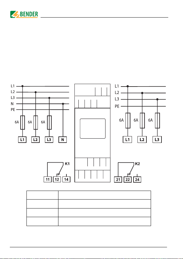
2. Wiring
Connect the device according the wiring diagram.
N
L1 L3L2
11 1412
21 2422
16
Terminal Connections
L1, L2, L3, (N) Connection to the system being monitored
11, 12, 14 Alarm relay K1
21, 22, 24 alarm relay K2
TGH1405en/01.2007
Page 17
5. Operation and setting
5.1 Display elements in use
The meaning of the display elements in use is listed in detail in the table
below.
Display elements in use Element Function
L1...L3N
Asy, %
U Hys,
Hz Hys
Conductor L1...L3 (phase),
neutral conductor
Asymmetry as %
< U,
Undervoltage (Alarm 2),
> U
overvoltage (Alarm 1)
r1, 1
Alarm relay K1,
r2, 2
alarm relay K2
Phase sequence clockwise,
R,
phase sequence counter-clockwise
l
(L = I.)
Response value hysteresis as %
%
< Hz,
Underfrequency (AL1 and AL2)
> Hz
Overfrequency (AL1 and AL2)
Frequency response value hysteresis as Hz
Response delay t
ton1,
ton2,
Response delay t
t,
Starting delay t,
toff
Release delay t
M
Fault memory active
Operating mode of the relays K1, K2
Password protection active
off
(K1),
on1
(K2)
on2
for K1, K2
TGH1405en/01.2007
17
Page 18

5.2 Function of the operating elements
Device front
ON AL1 AL2
T MENUR
Eleme
nt
Power On LED, green
ON
LED Alarm 1 lights (yellow):
AL1,
Response value > U reached
LED Alarm 2 lights (yellow):
AL2
Response value < U reached
AL1
Both LEDs light when the frequency
response values > Hz or < Hz are
and
reached.
AL2
405 V,
Un = 405 V between L1 and L2,
R,
Phase sequence clockwise,
Fault memory active
M
Test button (> 1.5 s):
T,
Indication of the display elements,
starting a self test;
Up key (< 1.5 s):
Menu items/values
Reset button (> 1.5 s):
R,
Deleting the fault memory;
Down key (< 1.5 s):
Menu items/values
MENU key (> 1.5 s):
Starting the menu mode;
MENU,
Enter key (< 1.5 s):
Confirm menu item, submenu item
and value.
Enter key (> 1.5 s):
Back to the next higher menu level.
Operation and setting
Functio n
18
TGH1405en/01.2007
Page 19
Operation and setting
5.3 Menu structure
All adjustable parameters are listed in the columns menu item and adjustable parameters. A display-like representation is used to illustrate
the parameters in the column menu item. Different alarm categories can
be assigned to the alarm relays K1, K2 via the submenus r1, r2. This is
done by activation or deactivation of the respective function.
Menu
AL
(response -
values)
Sub
menu
Menu
Activati
item
< U ON Undervoltage (Alarm 2),
> U ON Overvoltage (Alarm 1)
U Hys - Hysteresis < U / > U
Asy - Asymmetry alarm
< Hz OFF Underfrequency
> Hz OFF Overfrequency
Hz Hys - Hysteresis, frequency
PHS OFF Phase sequence R / L
Adjustable parameter
on
TGH1405en/01.2007
19
Page 20
Operation and setting
Menu
out
(output con-
trol)
t
(timing
check)
Set
(device con-
trol)
Sub
menu
r1
(K1: (assignment alarm
category)
r2
(K2: (assignment alarm
category)
Menu
Activati
item
M ON Fault memory (on, con, off )
1
2
1 Err OFF Device error at K1
r1 < U OFF Undervoltage K1
r1 > U ON Overvoltage K1
r1 Asy ON Asymmetry alarm K1
r1 < Hz ON Underfrequency alarm K1
r1 > Hz ON Overfrequency alarm K1
1 PHS ON Phase sequence alarm K1
2 Err OFF Device error K2
r2 < U ON Undervoltage K2
r2 > U OFF Overvoltage K2
r2 Asy ON Asymmetry alarm K2
r2 < Hz ON Underfrequency alarm K2
r1 > Hz ON Overfrequency alarm K1
2 PHS ON Phase sequence alarm K2
t on 1 - Response delay K1
t on 2 - Response delay K2
T- Starting delay
t off - Delay on release K1/K2
L1L2L3 - Measuring principle:
OFF Parameter setting via pass-
FAC - Re-establish factory settings
PrE - Manual preset
SYS - Function blocked
Adjustable parameter
on
-Operating mode K1 (n.o.)
- Operating mode K2 (n.c.)
phase -to-phase voltage
3 Ph,
phase-to-neutral voltage 3n
word
20
TGH1405en/01.2007
Page 21
Operation and setting
Menu
InF
HiS
Sub
menu
Menu
Activati
item
Clr - History memory for the first
Adjustable parameter
on
- Query hardware / software
version
alarm value, erasable
TGH1405en/01.2007
21
Page 22

Operation and setting
5.4 Display in standard mode
By default, the display shows the phase-to-phase voltage between L1
and L2. By pressing the Up or Down key, details about asymmetry, system frequency and phase sequence are displayed, for example. In order
to change the default display, confirm your choice with Enter.
In the standard mode, the currently measured voltages as
well as asymmetry, system frequency and phase sequence
can be displayed by using the Up and Down keys.
22
TGH1405en/01.2007
Page 23

Operation and setting
5.5 Display in menu mode
5.5.1 Parameter query and setting: overview Menu
item
Response value query and setting:
AL
out
t
SEt
InF
HiS
ESC
– Undervoltage: < U (AL2)
– Overvoltage: > U (AL1)
– Hysteresis of the voltage response values: Hys U
– Asymmetry: Asy (AL1 and AL2)
– Underfrequency: < Hz (AL1 and AL2)
– Overfrequency: > Hz (AL1 and AL2)
– Hysteresis of the frequency response values: Hys Hz
– Phase sequence: PHS (AL1 and AL2)
Configuration of the fault memory and the alarm relays:
– Activate/deactivate fault memory or to set con mode
– Select N/O operation (n.o.) or N/C operation (n.c.)
individually for each K1/K2
– Assign the alarm categories undercurrent, overcurrent,
underfrequency, overfrequency or device error individu-
Delay setting:
Parameter setting for device control
Query hard and software version
Query the first stored alarm value
Move to the next higher menu level (back)
ally to each K1/K2 (1, r1 / 2, r2).
– Response delay t
– Starting delay t
– Release delay t
– Select method of measurement 3Ph or 3n
– Enabling or disabling password protection, changing
the password
– Re-establish factory settings
– Start the preset function PrE manually.
– Service menu SyS blocked
Adjustable parameter
on1/ton2
(LED, relay)
off
TGH1405en/01.2007
23
Page 24
Menu structure
t > 1,5 s
t < 1,5 s
Operation and setting
t >1,5 s
AL
out
t
SEt
InF
HiS
ESC
t < 1,5 s
t > 1,5 s
ESC
24
TGH1405en/01.2007
Page 25

Operation and setting
Parameter settings
An example is given below on how to change the alarm response value
for overvoltage > U. Proceed as follows:
1. Press the MENU/Enter key for more than 1.5 seconds. The flashing short
symbol AL appears on the display.
2. Confirm with Enter. The parameter undervoltage
< U is flashing.
3. Press the Down key to select the parameter overvoltage > U. The
parameter > U flashes.
4. Confirm with Enter. A blinking "on" indicates that the response value
> U is being activated.
5. Confirm the activation of the response value with Enter. The associated
value in V appears on a flashing display.
6. Use the Up or Down key to set the appropriate response value. Confirm
with Enter. > U flashes.
7. You can exit the menu by:
– Pressing the Enter key for more than 1.5 seconds to reach the next
higher level or
– selecting the menu item ESC and confirming with Enter to reach the
next higher level.
The currently active segments are flashing! In the figures below,
the segments where device settings can be carried out are highlighted by an oval. The menu mode can be reached by pressing
the MENU key for more than 1.5 seconds.
TGH1405en/01.2007
25
Page 26

Operation and setting
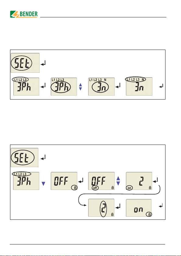
5.5.2 Setting the response values for under and overvoltage:
- Value of the undervoltage (< U)
- Value of the overvoltage (> U)
- Hysteresis (Hys) of the response values < U and > U
- Asymmetry (Asy) of the phases
- Phase sequence (PHS) anticlockwise (L) or clockwise (R) ,
in the example below from R to L
Setting the undervoltage response value < U
Setting the overvoltage response value> U
1x
2x
>1,5 s
2x
>1,5 s
26
TGH1405en/01.2007
Page 27

Operation and setting
Setting the hysteresis of the voltage response values
2x
Setting the asymmetry response value
3x
Setting the phase sequence response value
7x
2x
>1,5 s
2x
>1,5 s
TGH1405en/01.2007
2x
>1,5 s
27
Page 28

Operation and setting
5.5.3 Setting the response values for underfrequency, overfrequency and hysteresis
Setting the underfrequency response value < Hz
3x
2x
>1,5 s
Setting the overfrequency response value > Hz
4x
28
2x
>1,5 s
TGH1405en/01.2007
Page 29

Operation and setting
Setting the hysteresis of the frequency response values
5x
2x
>1,5 s
5.5.4 Setting the fault memory and operating principle of the alarm relays
Deactivating the fault memory
2x
>1,5 s
Setting the alarm relay K1 to N/C operation (n.c.)
TGH1405en/01.2007
1x
2x
>1,5 s
29
Page 30

Operation and setting
Setting the alarm relay K2 to N/O operation (n.o.)
2x
2x
>1,5 s
5.5.5 Assigning alarm categories to the alarm relays
Undervoltage, overvoltage, underfrequency, overfrequency, asymmetry,
phase sequence and device-related error messages of the voltage monitor can be assigned to the alarm relays K1 (r1, 1) and K2 (r2, 2). K1 is
set at the factory to signal an alarm in the event of overvoltage, and K2
is set to signal an alarm in the event of undervoltage.
A few assignment examples for alarm relay K1 are illustrated below:
Alarm relay K1: Assigning the category device error
3x
30
3x
>1,5 s
TGH1405en/01.2007
Page 31

Operation and setting
Alarm relay K1: Assigning the category undervoltage
3x
1x
Alarm relay K1: Deactivating the category overvoltage
3x
2x
3x
>1,5 s
3x
>1,5 s
TGH1405en/01.2007
31
Page 32
Operation and setting
Alarm relay K1: Deactivating the category asymmetry alarm
3x
3x
.
When an alarm relay (K1/K2) has been deactivated via
the menu, an alarm will not be signalled by the respective changeover contact! An alarm will only be indicated
by the respective alarm LED (AL1/AL2)!
Alarm relay K1: Deactivating the category phase sequence alarm
3x
>1,5 s
32
3x
4x
3x
>1,5 s
TGH1405en/01.2007
Page 33
Operation and setting
5.5.6 Setting the time delay
The following delays can be set:
Response delay t
Starting delay t (0...99 s) when the device is being started.
Common delay on release t
relevant when the fault memory M is deactivated.
(0...99 s) for K1, and t
on1
(0...99 s) for K1, K2. The setting t
off
(0...99 s) for K2
on2
is only
off
The operating steps for the setting of the response delay t
starting delay t are illustrated by way of example.
Setting the response delay t
on1
Setting the starting delay t
2x
TGH1405en/01.2007
and the
on1
2x
>1,5 s
2x
>1,5 s
33
Page 34
Operation and setting
5.5.7 Selecting the measuring method
Use this menu item to select between phase to N (3n) or phase-to-phase
(3Ph) measuring. If the device has been connected to the neutral conductor and the phase conductors you can use either measuring method.
2x
>1,5 s
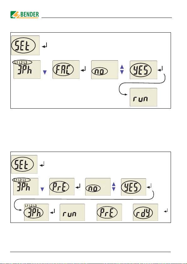
5.5.8 Factory setting and password protection
Use this menu to activate the password protection, to change the password or to deactivate the password protection. In addition, you can reset the device to its factory settings.
a) Activating the password protection
1x
34
2x
>1,5 s
TGH1405en/01.2007
Page 35
Operation and setting
b) Changing the password
1x
c) Deactivating the password protection
1x
2x
>1,5 s
2x
>1,5 s
TGH1405en/01.2007
35
Page 36
Operation and setting
5.5.9 Re-establishing the factory settings
2x
....
5.5.10 Manual activation of the preset function
During the operating process, the measuring principle is being queried.
You have two measuring principles to choose from, the three-phase-N-
measurement (3n) or the three-phase measurement (3Ph). In the example below, the three-phase measurement has been selected.
3x
36
....
....
TGH1405en/01.2007
2x
>1,5 s
Page 37
Operation and setting
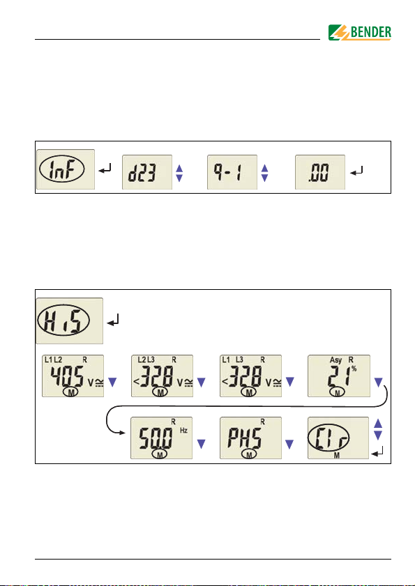
5.5.11 Device information query
This function is used to query the hardware (d...) and software (1.xx)
versions. After activating this function, data will be displayed as a scrolling text. Once one pass is completed you can select individual data sections using the Up/Down keys.
.... ....
5.5.12 History memory query
The history memory can be selected via the menu HiS. Use the Up and
Down keys to view the next display. If Clr is flashing, the history memory can be cleared by pressing the Enter key.
5.6 Commissioning
Prior to commissioning, check proper connection of the voltage moni-
TGH1405en/01.2007
37
Page 38
tor.
Operation and setting
After connecting a brand-new VMD421H... to a standard system of U
= 400 V 50 Hz, the response values are automatically set by the internal preset function:
Overvoltage = 440 V (400 V + 10 %) (50 Hz + 0.5 Hz)
Undervoltage = 340 V (400 V - 15 %) (50 Hz - 0.5 Hz)
Other operating ranges of the preset function are given in the technical data "response values" and in the description of the function.
5.7 Preset function/ factory setting
During the first start-up process the following response values are
automatically set related to U
Response value: overvoltage (> U): 1.1 U
Response value: undervoltage (< U): 0.85 U
Hysteresis U:
Underfrequency < Hz
Overfrequency > Hz
Hysteresis frequency (Hys Hz):
Fault memory M:
Operating principle K1
(> U, Asy):
Operating principle K2
(< U, Asy):
Asymmetry:
Phase sequence monitoring:
Starting delay:
Response delay:
Release delay:
Measuring method:
Password:
:
n
5 %
Off
Off
0.2 Hz
ON
N/O operation (n.o.)
N/C operation (n.c.)
30 %
Off
t = 0 s
t
on1
t
on2
t
= 0.5 s
off
3Ph (phase-to-phase voltage)
0, Off
= 0 s
= 0 s
n
n
n
38
TGH1405en/01.2007
Page 39

6. Technical data VMD421H
6.1 Data in tabular form
( )* = factory setting
Insulation coordination acc. to IEC 60664-1/IEC 60664-3
Rated insulation voltage ....................................................................................................................................... 400 V
Rated impulse voltage/pollution degree........................................................................................................... 4 kV / III
Protective separation (reinforced insulation) between............................ (N, L1, L2, L3) - (11, 12, 14) - (21, 22, 24)
Voltage test acc. to IEC 61010-1:
(N, L1, L2, L3) - (11, 12, 14) ............................................................................................................................... 3.32 kV
(N, L1, L2, L3) - (21, 22, 24) ............................................................................................................................... 2.21 kV
Supply voltage
Supply voltage U
Power consumption ............................................................................................................................................ ≤ 5 VA
Measuring circuit
Measuring range (r.m.s. value) (L-N) ..................................................................................................... AC 0...288 V
Measuring range (r.m.s. value) (L-L) ...................................................................................................... AC 0...500 V
Rated frequency f
Frequency range .......................................................................................................................................... 10...500 Hz
Response values
Type of distribution system ...................................................................................................... 3(N) AC / 3 AC (3 AC)*
Undervoltage < U (Alarm 2) (measuring method: 3Ph / 3n ) ........................................ AC 70...500 V / 70...288 V
Overvoltage > U (Alarm 1) (measuring method: 3Ph / 3n ) .......................................... AC 70...500 V / 70...288 V
Resolution of setting U ............................................................................................................................................... 1 V
Preset function for 3 AC measurem ent:
Undervoltage< U (0.85 U
Overvoltage > U (1.1 U
Preset function for 3(N)AC measurement:
Undervoltage < U (0.85 U
Overvoltage > U (1.1 U
....................................................................................................... none (internally supplied by Un)
s
....................................................................................................................................... 15...460 Hz
n
)* for Un = 400 V/ 208 V ........................................................................... 340 V / 177 V
n
)* for Un = 400 V/ 208 V .............................................................................. 440 V / 229 V
n
)* for Un = 230 V / 120 V ......................................................................... 196 V / 102 V
n
)* for Un = 230 V / 120 V ............................................................................. 253 V / 132 V
n
TGH1405en/01.2007
39
Page 40

Technical data VMD421H
Asymmetry ......................................................................................................................................... 5...30 % (30 %)*
Phase failure...................................................................................................................... by setting of the asymmetry
Phase sequence .............................................................................................. clockwise/ anticlockwise rotation (off)*
Relative percentage error, voltage at 50 Hz / 60 Hz ........................................................................ ±1.5 %, ±2 digits
Relative percentage error in the voltage range of 15 Hz...460 Hz....................................................... ±3 %, ±2 digits
Hysteresis U ......................................................................................................................................... 1...40 % (5 %)*
Underfrequency < Hz .............................................................................................................................. 10...500 Hz**
Overfrequency > Hz ................................................................................................................................. 10...500 Hz**
Resolution of setting f 10.0...99.9 Hz .................................................................................................................. 0.1 Hz
Resolution of setting f 100...500 Hz ....................................................................................................................... 1 Hz
Preset function:
Underfrequency for f
Overfrequency for f
= 16.7 Hz / 50 Hz / 60 Hz / 400 Hz ............................... 16.2 Hz / 49.5 Hz / 59.5 Hz / 399 Hz
n
= 16.7 Hz / 50 Hz / 60 Hz / 400 Hz ................................. 17.2 Hz / 50.5 Hz / 60.5 Hz / 401 Hz
n
Hysteresis frequency Hys Hz .......................................................................................................... 0.2...2 Hz (0.2 Hz)*
Relative percentage error in the frequency range of 15 Hz...460 Hz............................................... ±0,2 %, ±1 digits
Specified time
Starting delay ........................................................................................................................................... 0...99 s (0 s)*
Response delay t
Release delay t
Operating time voltage t
Operating time frequency t
Response time t
Discharging time energy backup on power failure .......................................................................................... ≥ 2.5 s
............................................................................................................................. 0...99 s (0 s)*
on1/2
................................................................................................................................... 0...99 s (0.5 s)*
off
............................................................................................................................ ≤ 140 ms
ae
........................................................................................................................ ≤ 335 ms
ae
............................................................................................................................. tan = tae + t
an
on1/2
Charging time energy storage ............................................................................................................................. ≤ 60 s
Recovery time t
............................................................................................................................................. ≤ 300 ms
b
Displays, memory
Display..................................................................................................... LC display, multi-functional, not illuminated
Display range, measured value.................................................................................................................... AC 0...500 V
Operating error, voltage at 50 Hz / 60 Hz ........................................................................................ ±1.5 %, ±2 digits
Operating error in the voltage range of 15...460 Hz............................................................................. ±3 %, ±2 digit
Operating error in the frequency range of 15...460 Hz...................................................................... ±0.2 %, ±1 digit
History memory (HiS) for the first alarm value............................................................... data record measured values
Password ......................................................................................................................................... Off / 0...999 (OFF)*
Fault memory (M) alarm relay ...................................................................................................... on / off / con (on)*
40
TGH1405en/01.2007
Page 41

Technical data VMD421H
Switching elements
Number of changeover contacts............................................................................................................... 2 x 1 (K1, K2)
Operating principle.......................................................................................... N/C operation n.c. / N/O operation n.o.
...................... K2: Err, < U, > U, Asy, < Hz, > Hz, PHS (undervoltage < U, asymmetry Asy, N/C operation n.c.)*
.......................... K1: Err, < U, > U, Asy, < Hz, > Hz, PHS (overvoltage >U, asymmetry Asy, N/O operation n.o.)*
Electrical service life under rated operating conditions.................................................... 10000 switching operations
Fault memory ............................................................................................................................................ on / off (on)*
Contact data acc. to IEC 60947-5-1:
Utilization category ............................................................. AC 13 ......... AC 14........ DC-12........ DC-12....... DC-12
Rated operational voltage ................................................... 230 V ......... 230 V ........... 24 V......... 110 V....... 220 V
Rated operational current ........................................................ 5 A ............. 3 A ............. 1 A.......... 0.2 A ........ 0.1 A
Minimum contact load................................................................................................................1 mA at AC/DC ≥ 10 V
Environment/EMC
EMC ................................................................................................................................................................. IEC 61326
Operating temperature ......................................................................................................................... -25 ºC...+55 ºC
Classification of climatic conditions acc. to IEC 60721:
Stationary use (IEC 60721-3-3) ........................................................3K5 (except condensation and formation of ice)
Transportation (IEC 60721-3-2) ........................................................2K3 (except condensation and formation of ice)
Storage (IEC 60721-3-1) ...................................................................1K4 (except condensation and formation of ice)
Classification of mechanical conditions acc. to IEC 60721:
Stationary use (IEC 60721-3-3) ..............................................................................................................................3M4
Transportation (IEC 60721-3-2) .............................................................................................................................. 2M2
Storage (IEC 60721-3-1) ......................................................................................................................................... 1M3
Connection
Connection ............................................................................................................................................ screw terminals
Connection properties:
rigid/ flexible ...................................................................................................... 0.2...4 / 0.2...2.5 mm
Multi-conductor connection (2 conductors with the same cross section):
rigid/ flexible .................................................................................................................. 0.2...1.5 mm
2
/ AWG 24...12
2
/ 0.2...1.5 mm
Stripping length ............................................................................................................................................... 8...9 mm
Tightening torque....................................................................................................................................... 0.5...0.6 Nm
Other
Operating mode ........................................................................................................................... continuous operation
2
TGH1405en/01.2007
41
Page 42

Technical data VMD421H
Mounting position ................................................................................................... vertically, see dimension diagram
Degree of protection DIN EN 60529, internal components ..................................................................................... IP30
Degree of protection DIN EN 60529, terminals........................................................................................................ IP20
Enclosure material.....................................................................................................................................polycarbonate
Flammability class............................................................................................................................................ UL94 V-0
DIN rail mounting acc. to................................................................................................................................. IEC 60715
Screw fixing ......................................................................................................................... 2 x M4 with mounting clip
Software version ......................................................................................................................................... D239 V1.21
Weight ............................................................................................................................................................... ≤ 240 g
( )* = factory setting
**Technical data are only guaranteed within the rated frequency range of 15...460 Hz.
6.2 Ordering information
Device type
VMD421H-D-3
Nominal system voltage
U
*
n
3(N)AC 70...500 V/ 288 V
15...460 Hz
Art. No.
B 9301 0007
*Absolute values of the voltage range
Mounting clip for screw fixing (1 piece per device, accessories) B 9806 0008
42
TGH1405en/01.2007
Page 43
Technical data VMD421H
6.3 Voltage timing diagram
überwachte
Spannung/
Voltage
being monitored
Versorgungsspannung/
Supply voltage
Alarm-LEDs
Arbeitsstrom/
N/0
Alarm relays
MEM off
Ruhestrom/
N/C
Arbeitsstrom/
N/0
Alarm relays
MEM on
Ruhestrom/
N/C
11
21
11
21
> U
Hys
Hys
< U
ON
AL1
AL2
t
an
Überspannung/
Overvoltage
t
off
Dt < t
an
t
an
Dt
Start
t
U
S
14
12
24
22
14
12
24
22
t
an
Unterspannung/
Undervoltage
t
off
Dt < t
an
t
an
Dt
t
t = Starting delay
t
= Response time
an
t
= Release delay
off
TGH1405en/01.2007
43
Page 44

Technical data VMD421H
6.4 Timing diagram: asymmetry, phase failure, phase sequence
Asymmetrie/
Asymmetry
Asy %
t
L1
L2L3
t
an
t
off
t < t
D
t
an
Phasenausfall/
Phase failure
Phasenfolge/
Phase sequence
Versorgungsspannung/
Supply voltage
Alarm-LEDs
Arbeitsstrom/
N/O
Alarm relays
MEM off
Ruhestrom/
N/C
Arbeitsstrom/
N/O
Alarm relays
MEM on
Ruhestrom/
N/C
44
PHS (L, R)
"ON"
"AL1" "AL2"
11
21
11
21
t
L1
L2L3
t
L1
L2L3
t
14
12
24
22
14
12
24
22
TGH1405en/01.2007
Page 45

INDEX
A
Adjustable parameters, list
Automatic self test
C
currently measured values
- asymmetry
- phase sequence
- phase-to-phase voltage 22
- rated frequency 22
D
Deleting the fault alarms
Device features 9
Diagram
- asymmetry, phase failure,
phase sequence
- Voltage timing diagram
Discharging time energy backup on
power failure 40
Display elements in use
Display in standard mode
E
Enter key
Example of parameter setting
22
18
19
11
22
18
44
43
17
22
25
F
factory setting
Fast commissioning for Un = 400 V
5
Fault memory in the operating
mode on, off or con 9, 11
Function
I
Installation and connection 15
K
K1: assignment alarm category
K2: assignment alarm category 20
L
LED Alarm 1 lights
LED Alarm 2 lights 18
M
Malfunction
Manual self test
Manual, target group
Menu
- AL (response values)
- HiS (history memory for the
- InF (hard and software ver-
13, 38
9
18
11
11
first alarm value)
20
5
19
21
TGH1405en/01.2007
45
Page 46

sion) 21
- out (output control) 20
- Set (device control
- t (timing check)
Menu structure, overview 19
Mounting clip for screw fixing
O
Operating elements, function
Operation and setting
Ordering information 42
P
Parameter query and setting, over-
23
view
Parameter setting
- Activating or deactivating the
password protection
- Assigning alarm categories to
the alarm relays
- deactivating the fault memo-
ry 29
- Response value setting
- Selecting the measuring
method: Phase-N or phase-
34
phase
- Setting the operating principle of the alarm relays
- Setting the time delay
Password protection
Preset function
10
20
20
42
18
17
34
30
26
29
33
12
R
Release delay toff
Reset button
Response delay ton
Response value setting
- asymmetry
- Hysteresis frequency
- Hysteresis U 27
- Overfrequency (> Hz)
- phase sequence 27
- Underfrequency (< Hz) 28
- Undervoltage (< U) und
Überspannung (> U)
S
Starting delay t
Starting the menu mode 18
T
Technical data
Test button 18
Time delays 9, 12
V
Voltage timing diagram
W
Wiring diagram
Work activities on electrical instal-
lations
12
18
12
27
29
28
26
12
39
43
16
7
46
TGH1405en/01.2007
Page 47

Page 48

Dipl.-Ing. W. Bender GmbH & Co.KG
Londorfer Str. 65 • 35305 Grünberg • Germany
Postfach 1161 • 35301 Grünberg • Germany
Tel.: +49 (0)6401-807-0
Fax: +49 (0)6401-807-259
E-Mail: info@bender-de.com
Web-Server: http://www.bender-de.com
 Loading...