

Page 1
Operating Manual
UNIMET® 300ST
Testing system for
electrical safety
Software version: 3.2 and later
TGH1365en/10.2012
Page 2

Bender GmbH & Co. KG
Londorfer Str. 65 • 35305 Grünberg • Germany
Postfach 1161 • 35301 Grünberg • Germany
Tel.: +49 6401 807-0
Fax: +49 6401 807-259
E-mail: info@bender-de.com
Web: http://www.bender-de.com
© Bender GmbH & Co. KG
All rights reserved.
Reprinting only with permission
of the publisher.
Subject to change!
Page 3

Table of Contents
1. How to get the most out of this manual ............................................................. 5
1.1 About this operating manual .............................................................................................. 5
1.2 Technical support .................................................................................................................... 5
1.3 Explanation of symbols and notes ..................................................................................... 6
2. Safety instructions .................................................................................................. 7
2.1 Delivery ........................................................................................................................................ 7
2.2 Intended use .............................................................................................................................. 7
2.3 Skilled persons .......................................................................................................................... 7
2.4 General safety instructions ................................................................................................... 7
2.5 Delivery conditions, guarantee, warranty and liability .............................................. 8
3. System description ................................................................................................. 9
3.1 Function ...................................................................................................................................... 9
3.2 Standard-compliant tests .................................................................................................. 10
3.3 System components ............................................................................................................10
3.4 Controls .................................................................................................................................... 12
4. Operation and configuration ............................................................................. 13
4.1 Commissioning ...................................................................................................................... 13
4.1.1 Connecting a printer ............................................................................................................ 14
4.1.2 Connecting the keyboard and barcode scanner ....................................................... 14
4.2 Principle of operation .......................................................................................................... 14
4.2.1 Operating the device ........................................................................................................... 14
4.2.2 Operation via the keyboard .............................................................................................. 15
4.2.3 Reading in with the barcode reader .............................................................................. 15
4.3 Main menu .............................................................................................................................. 16
4.4 Test engineer catalogue ..................................................................................................... 16
4.5 Device settings ....................................................................................................................... 19
4.5.1 Test probe calibration ......................................................................................................... 20
4.5.2 Device type query ................................................................................................................. 21
4.5.3 Warm-up and cool-down period ..................................................................................... 21
4.5.4 Changing the company name ......................................................................................... 22
4.5.5 Time/date ................................................................................................................................. 22
TGH1365en/10.2012
3
Page 4

4.5.6 RS-232 parameters ................................................................................................................ 23
4.5.7 Buzzer On/Off ......................................................................................................................... 24
4.5.8 Summer time/winter time ................................................................................................. 24
4.5.9 Language/Sprache ............................................................................................................... 25
4.5.10 Firmware update ................................................................................................................... 25
4.6 Information .............................................................................................................................. 28
5. Testing and measuring ........................................................................................ 29
5.1 Testing via classification ..................................................................................................... 29
5.1.1 Classification ........................................................................................................................... 29
5.1.2 Tests ........................................................................................................................................... 33
5.1.3 Evaluating the test result .................................................................................................... 40
5.2 Recurrent test and device catalogue ............................................................................. 41
5.2.1 Collective printout ................................................................................................................ 42
5.2.2 Backing up the device catalogue .................................................................................... 43
5.3 Single test ................................................................................................................................. 49
Inhaltsverzeichnis
6. Maintenance and calibration ............................................................................. 51
6.1 Calibration ............................................................................................................................... 51
6.2 Changing the battery ........................................................................................................... 51
6.3 Error messages ....................................................................................................................... 51
6.4 Disposal .................................................................................................................................... 52
7. Data ......................................................................................................................... 53
7.1 Standards ................................................................................................................................. 53
7.1.1 Application standards ......................................................................................................... 53
7.1.2 Design standards ................................................................................................................... 53
7.2 Test steps .................................................................................................................................. 54
7.3 Technical specifications ...................................................................................................... 56
7.4 Ordering data ......................................................................................................................... 57
INDEX ...........................................................................................................................59
4
TGH1365en/10.2012
Page 5

1. How to get the most out of this manual
1.1 About this operating manual
This operating manual describes the UNIMET® 300ST with the software version indicated on the cover page. The functions and processes described may vary from those featured in other versions. It is
designed for electrically skilled persons working in electrical engineering and electronics.
Please read this operating manual before using the devices. This documentation must be kept in an
easily accessible location near to the device.
Although great care has been taken in the drafting of this operating manual, it may nevertheless
contain errors and mistakes. The Bender Group cannot accept any liability for injury to persons or
damage to property resulting from errors or mistakes in this manual.
Each of the registered trademarks which appears in this document remains the property of its owner.
1.2 Technical support
As a Bender customer, you will receive technical support and assistance in the event of queries relating to equipment you have purchased. Please contact our Service Department or your next Bender
agency for more information:
Service-Hotline:
0700-BenderHelp (Telefon und Fax)
Carl-Benz-Straße 8 • 35305 Grünberg • Germany
Tel: +49 6401 807-760 • Fax: +49 6401 807-629
E-Mail: info@bender-service.com • www.bender-de.com
TGH1365en/10.2012
5
Page 6
How to get the most out of this manual
Danger !
Warning
Caution
1.3 Explanation of symbols and notes
The following terms and symbols are used to denote hazards and instructions in Bender documentation:
This symbol indicates an immediate risk to life and limb.
Failure to observe the associated instructions and take appropriate precautions
will result in death, serious physical injury or substantial damage to property.
This symbol indicates a potential risk to life and limb.
Failure to observe the associated instructions and take appropriate precautions
may result in death, serious physical injury or substantial damage to property.
This symbol indicates a potentially dangerous situation.
Failure to observe the associated instructions and take appropriate precautions
may result in minor physical injury or damage to property.
This symbol indicates important information about the correct use of the equipment purchased.
Failure to observe the associated instructions can result in equipment malfunctioning or cause problems in the environment in which it is being used.
This symbol indicates tips for using the equipment and particular useful information. This type of information will help you to optimise your use of the equipment.
6
TGH1365en/10.2012
Page 7

2. Safety instructions
2.1 Delivery
Inspect the dispatch packaging and equipment packaging for damage, and compare the contents
of the package with the delivery documents. Equipment damaged in transit must not be used. If
equipment has been damaged in transit, contact Bender immediately.
Equipment may only be stored in areas where it is protected against dust, damp, spray water and
dripping water and where the specified storage temperatures can be assured.
The selling company’s "General conditions of sale and delivery" always apply.
2.2 Intended use
The UNIMET® 300ST has been designed exclusively for use in the area of application stipulated in the
chapter entitled "System description" on page 9.
Intended use also implies:
Observance of all instructions in this operating manual and
Compliance with any test intervals
Use which deviates from or is beyond the scope of these technical specifications is considered noncompliant. The Bender Group cannot accept any liability for damage resulting from such use.
2.3 Skilled persons
Only electrically skilled persons may work on Bender products. Personnel who are familiar with the
installation, commissioning and operation of the equipment and have undergone appropriate training are considered skilled persons. Such personnel must have read this manual and understood all
instructions relating to safety.
2.4 General safety instructions
Bender devices are designed and built in accordance with the state of the art and accepted rules in
respect of technical safety. However, the use of such devices may introduce risks to the life and limb
of the user or third parties and/or result in damage to Bender devices or other property.
Only use Bender equipment:
– As intended
– In perfect working order
– in compliance with the accident prevention regulations and guidelines applicable at the loca-
tion of use
Eliminate all faults that may endanger safety immediately
Do not make any unauthorised changes and only use replacement parts and optional accesso-
ries purchased from or recommended by the manufacturer of the equipment. Failure to
observe this requirement can result in fire, electric shock and injury
Information plates must always be clearly legible. Replace damaged or illegible plates immedi-
ately.
TGH1365en/10.2012
7
Page 8

Safety instructions
2.5 Delivery conditions, guarantee, warranty and liability
The conditions of sale and delivery set out by Bender apply.
For software products, the "Softwareklausel zur Überlassung von Standard-Software als Teil von
Lieferungen, Ergänzung und Änderung der Allgemeinen Lieferbedingungen für Erzeugnisse und
Leistungen der Elektroindustrie" (software clause in respect of the licensing of standard software as
part of deliveries, modifications and changes to general delivery conditions for products and services in the electrical industry) set out by the ZVEI (Zentralverband Elektrotechnik- und Elektronikindustrie e.V., the German Electrical and Electronic Manufacturers' Association) also applies.
Delivery and payment conditions along with a copy of the software clause can be obtained from
Bender in printed or electronic format.
8
TGH1365en/10.2012
Page 9

3. System description
3.1 Function
The UNIMET® 300ST is used to test electrical safety. It has been designed for following areas of use:
Hospital and care beds
"Prüfung nach Instandsetzung, Änderung elektrischer Geräte - Wiederholungsprüfung elek-
trischer Geräte" (Inspection after repair, modification of electrical appliances - Periodic inspection on electrical appliances) DIN VDE 0701-0702 (VDE 0701-0702):2008-06
with appropriate adapter
according to DIN VDE 0701-0702 and DIN EN 62353
* Use the DS32DCT three-phase current adapter to test devices not being in operation.
Use the DS32A three-phase current adapter to test devices during operation.
The test system supplies measurement results which it evaluates immediately in order to classify the
test as "passed" or "failed". The test sequence which follows classification contains a visual inspection
and a functional test in addition to the electrical tests. The test sequence can be carried out automatically or manually depending on the device under test.
The test results can be displayed on the screen, saved or printed out using an external printer. In the
event of unexpected results, the DUT can be inspected in more detail by carrying out a single test.
The device catalogue provides memory space for the test results from up to 600 tested beds or devices.
*
also protection class I and II three-phase electrical equipment
Tests can be transferred to a PC software program via the RS-232 interface. This software is included
with the UNIMET
®
300ST. For recurrent tests, the data stored in the PC software are transferred back
to the UNIMET® 300ST. The RS-232 interface is also used for any subsequent updates of the internal
operating software on the test system.
The test engineer catalogue can be beneficial if more than one person is working with the test system. Test engineers already registered on the system are simply selected from this folder. There is no
need to re-enter the name of the test engineer. The names of up to ten test engineers can be stored.
The LC display is backlit. For entering data, a standard keyboard or barcode reader can be connected
to the PS/2 interface.
UNIMET® 300ST has been designed solely for use with earthed systems. If the test
system is used other than as intended, i.e. on an IT system, the measured values
of any leakage currents will not be reproducible. The test result cannot be used.
Alternative measurements of leakage currents, however, carried out with the
UNIMET® 300ST in IT systems will deliver correct test results.
TGH1365en/10.2012
9
Page 10

System description
3.2 Standard-compliant tests
The UNIMET® 300ST carries out measurements and tests according to the following standards (see
also chapter "7.1 Standards"):
IEC 62353:2007-05
DIN EN 62353 (VDE 0751-1):2008-08
ÖVE/ÖNORM EN 62353:2009-01-01
DIN VDE 0701-0702 (VDE 0701-0702):2008-06
ÖVE E8701-1:03-01
The UNIMET® 300ST carries out the following measurements and tests:
Visual inspection
System voltage
Measurement of current consumption and calculation of power consumption
PE resistance for Protection Class I equipment
Insulation resistance
Equipment leakage current according to the differential measurement method or by direct
measurement
Equipment leakage current -Alternative method
Touch or PE conductor current according to the differential measurement method or by direct
measurement
Functional test
3.3 System components
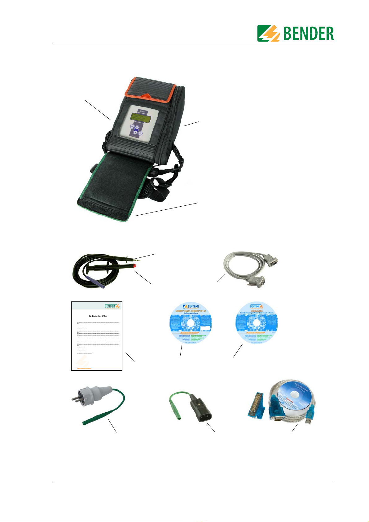
The following accessories are supplied with the UNIMET® 300ST test system:
1 Carrying bag For the storage and transport of the test system
and its accessories. Accessories are kept in the side
pocket and the inside pocket.
2 Test probe For testing accessible parts of the DUT
3 Test terminal (safety claw grip) For connection to accessible parts of the DUT
4 Interface cable (null modem
cable)
5 Calibration certificate Proof of the calibration carried out in the factory
6 Technical device manual on CD Test system manual
7 UNIData300 PC software (CD) UNIData300 software for
8 VK701-6 Adapter Schuko
(German)
9 VK701-7 Adapter for non-
heating appliances
10 USB1.1 RS-232 converter Enables data exchange between the RS-232
Enables data to be exchanged between the test
system and a PC (RS-232 interface)
- backing up the device catalogue on a PC
- transferring a firmware update to the
UNIMET® 300ST
For testing extension cables and socket strips
For testing device connecting cables
interface of the UNIMET® 300ST and the USB port
of a PC (with installation CD)
10
TGH1365en/10.2012
Page 11
1
4
7
6
5
9
8
10
2
3
Side pocket
contains the accessories
Pos. 2, 3, 4, 8, 9, 10
Inside pocket
contains the accessories
Pos. 6, 7
System description
The test system and its accessories
TGH1365en/10.2012
Fig. 3.1: Accessories
11
Page 12
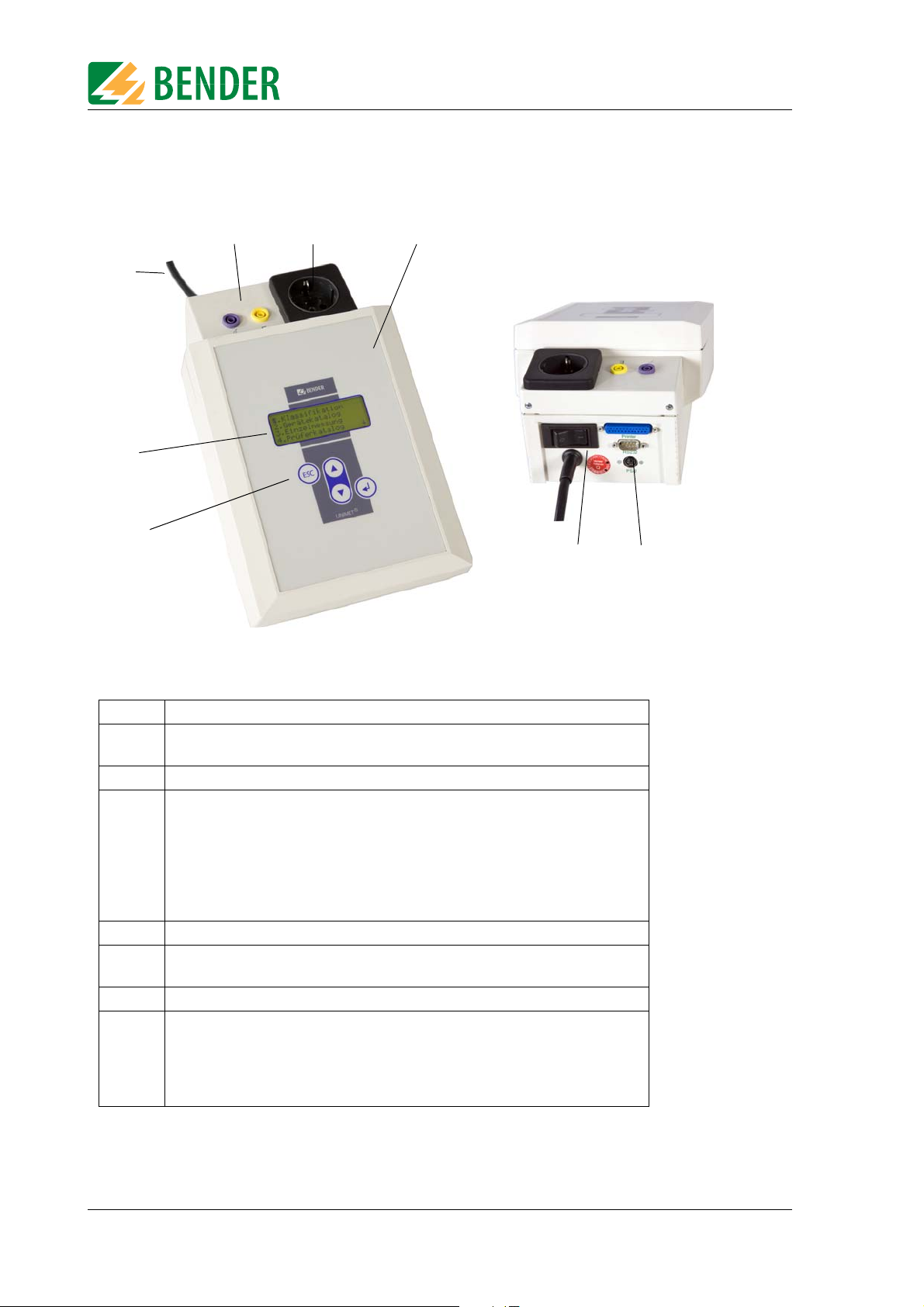
3.4 Controls
2
8
7
6
5
4
3
1
System description
1 Control buttons
2 Backlit LCD for displaying the user menu and the measurement results. Four
lines of 20 characters each.
3 Permanently attached power cable for connection to the supply voltage.
4Sockets
- violet: Connection for test probe for testing accessible parts of the
device under test.
- yellow (E): for a second measuring lead when the low-resistance continuity
5 Test socket: This is where the DUT's power supply cable is plugged in.
6 Durable plastic enclosure, with pushbuttons for safe storage in the carrying
bag.
7 Power switch with thermo-magnetic circuit-breaker.
8Interfaces
- RS-232 interface, 9-pin, galvanically isolated, for connection to a PC
- Centronics interface for connection to a printer
- PS/2 port for connection to an external standard keyboard and a barcode
reading wand or scanner.
of the PE conductor is to be measured between two points (e.g.,
on single-phase, permanently installed devices or extension
cables).
12
TGH1365en/10.2012
Page 13
4. Operation and configuration
Warning
Caution
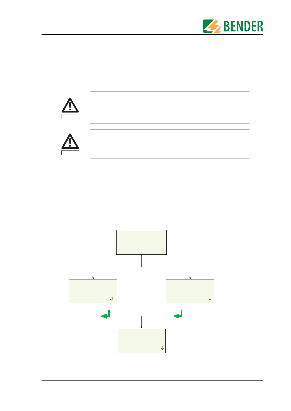
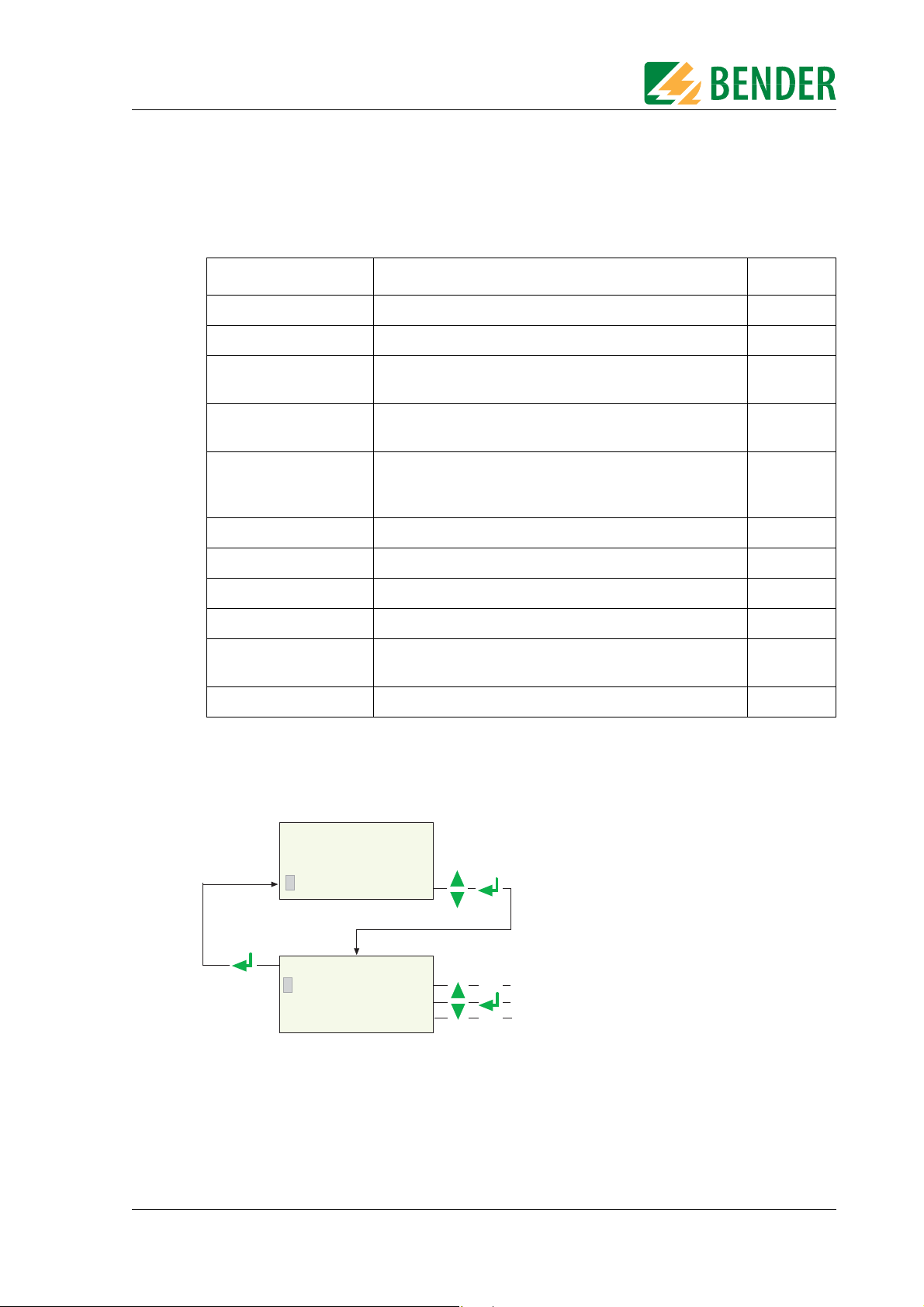
-----------------------------Test eng. logged on:
Hofmann
Next:
** WARNiNG **
No test engineer
logged on!
Next:
UNIMET300ST
Test system for
electrical safety
BENDER GMBH & CO.KG
1. Classification
2. Device catalogue
3. Single test
4. Test eng. catalog
If no test engineer
has logged on yet
If a test engineer has
already logged on
Main menu
Press the ENTER key
or wait 3 seconds
leads to main menu
4.1 Commissioning
Inspect UNIMET® 300ST, its supply cable and measuring leads connected to it for
visible damage on the outside. Do not operate equipment showing any visible
damage.
The UNIMET® 300ST must always be connected to the supply voltage indicated
on the nameplate. Failure to observe this requirement may damage the test system and any device under test connected to it.
1. Lay the UNIMET® 300ST down on an even surface with the coloured edges of the bag facing
up. Open the two covers (Velcro fasteners).
2. Connect the UNIMET® 300ST to the supply voltage using the permanently attached power
cable.
3. Switch on the device using the power switch.
The test system logs on with a beep (only when the buzzer is switched on) and displays the welcome
text:
The test system is now ready for operation. The main menu appears.
TGH1365en/10.2012
13
Page 14

Operation and configuration
Caution
4.1.1 Connecting a printer
Earthed printers can affect the measurements. Therefore, during the measurements, make sure that either
- the Centronics interface is not connected to an earthed printer or
- the Centronics interface is electrically isolated via a suitable component.
A printer can be connected to print out the test results. Providing that:
The printer used has an IBM 8-bit character set
The printer is set to IBM emulation
®
GDI printers (GDI = Graphic Device Interface) are not suitable for the UNIMET
300ST.
You need a standard printer cable (25-pole D-Sub plug to Centronics) to connect the printer. This cable is not included with the equipment.
4.1.2 Connecting the keyboard and barcode scanner
A keyboard and/or barcode reading wand or barcode scanner can be used to make it easier to input
the ID numbers and names of test engineers. UNIMET® 300ST supports the PS/2 interface to which
either a standard keybboard, a PS/2 barcode-pen reader or PS/2 barcode scanner can be connected.
If an AR100 barcode-pen reader is connected to a PS/2 keyboard switch cable (see “Ordering data”
auf Seite 57.), it can be connected to a keyboard at the same time. If no keyboard is connected, then
plug the keyboard simulator supplied with the AR100 barcode-pen reader to this port.
The keyboard and barcode pen reader or barcode scanner can be plugged in and unplugged during
operation. Adjustments on the UNIMET are not necessary. The keyboard and barcode pen reader
must not be connected before switching on the UNIMET. This increases flexibility during testing.
When the UNIMET detects a PS/2 keyboard, then the "Num-Lock" LED lights up. The LED indicates
that the keyboard is ready.
4.2 Principle of operation
4.2.1 Operating the device
All the functions of the UNIMET® 300ST are controlled using the four control keys and the displays on
the screen. The current position on the menus is indicated by a flashing marker (cursor).
ESC The ESC button enables you to leave functions without making
Use the arrow buttons to move the cursor up or down on the menus.
Use the Enter button to confirm selection of the current menu item.
changes. It also enables you to return to the main menu.
14
TGH1365en/10.2012
Page 15

Operation and configuration
4.2.2 Operation via the keyboard
An external keyboard makes it easy to enter the names and ID numbers of the test engineers. You
can also operate the UNIMET entirely via the keyboard. The Cursor block " ", " ", " " "ENTER"
and "ESC" keys have the same function as the buttons on the front of the UNIMET.
Note when entering text:
The text entry cannot be longer than 20 characters. The UNIMET will truncate longer entries to
20 characters.
You can enter all characters which can be selected directly on UNIMET.
Upper and lower case is available but not umlauts.
The numeric keypad can only be used to enter digits. The LED "Num-Lock" therefore lights up
constantly.
When entering text, the following keys can be used to edit the text:
" ", " " (Cursor block), " " (Backspace), Del, Home.
Entries via the keyboard can also be combined with texts read in from the barcode scanner and
barcode reading wand.
Save the entry after entering the last character by
– by holding down the Enter button " " on the UNIMET for approx. 3 seconds
– or by pressing the " " ENTER key on the keyboard once.
4.2.3 Reading in with the barcode reader
Refer to the operating instructions for the barcode reading wand or barcode scanner.
The AR100 barcode reading wand (see “Ordering data” auf Seite 57.) reads more reliably by sweeping it quickly over the barcode. Also follow the instructions for the barcode reading wand. Barcodes
can be read both forwards and backwards.
The data string which is read in can be up to 20 characters long. The UNIMET will truncate longer entries to 20 characters.
When reading in the names and ID numbers of new test engineers, the input screen will remain
open. This allows you to check the entry and change or replace it if necessary. .
You can delete the entry and go to the previous menu by holding down
– the "ESC" button on the UNIMET for approx. 3 seconds
– or by pressing the "ESC" key on the external keyboard once.
Save the entry by holding down
– the Enter button " " on the UNIMET for approx. 3 seconds
– or by pressing the " " Enter key on the external keyboard once.
You can use the barcode scanner or barcode reading wand to call up tests from the device catalogue
again using the ID number. In this case, after successfully reading in the barcode, it will immediately
switch to the next screen of the operating process.
TGH1365en/10.2012
15
Page 16
Operation and configuration
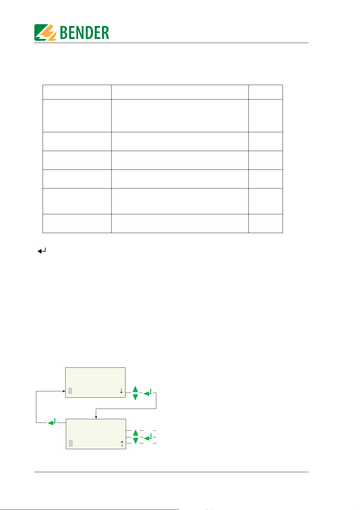
Main menu
1. Select "Test eng. catalog."
ESC
- Select and log on test engineer
- Enter and log on new test engineer
- Delete existing test engineer
2. select required function:
1. Exit
2. Select test eng.
3. Enter new test eng
4. Delete test eng.
1. Classification
2. Device catalogue
3. Single test
4. Test eng. catalog.
4.3 Main menu
All UNIMET® 300ST functions and submenus can be accessed from the main menu.
Menu item Function Page
1. Classification Answer the questions that appear on the screen. The
test system will identify the required test steps and
limits to be observed. The assisted test sequence will
guide you through all necessary steps to be taken.
2. Device catalogue The test results, tests and limits of the device tested by
the test system are stored in the device catalogue.
3. Single test Test steps can be called up in the form of single tests
and repeated as often as required.
4. Test engineer
catalogue
5. Device setting Settings for test probe, type query, warm-up period,
6. Info Provides information about the device names,
Select test engineer, enter new test engineer, delete
test engineer
company name, clock, RS-232 interface, buzzer,
language and update
software version and serial number of the device.
29
41
49
16
19
28
Each submenu is accessed by selecting it with the arrow buttons and confirming by pressing the
" " button.
4.4 Test engineer catalogue
The names of the test engineers are stored in the "Test engineer catalogue". The test engineer whose
name appears in the test protocol is also logged on here. You should therefore set the name of the
test engineer before carrying out the first test.
The test catalogue can be particularly beneficial if more than one person is working with the test system. Test engineers already registered on the system are simply selected from the test catalogue using the arrow buttons. There is no need to re-enter the name of the test engineer.
A name of a test engineer cannot be longer than twenty characters. The names of up to ten test
engineers can be stored.
16
TGH1365en/10.2012
Page 17
Operation and configuration
ENTER TEST ENG. NAME:
_
Char.: A-Z, 0-9, -. /
Exit: ESC Next:
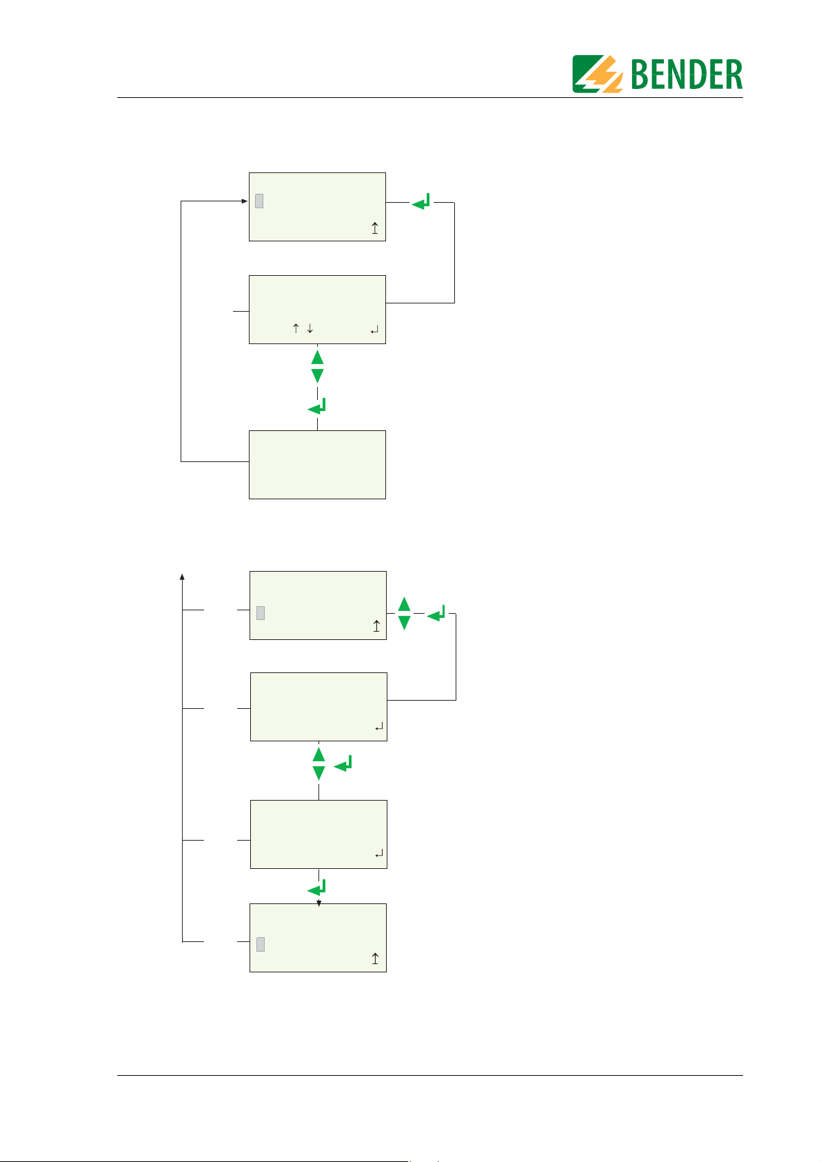
1. Select “Enter new test eng”
2. Use the arrow keys to select the first characters
and then press the ENTER key
4. After entering the last character,
press and hold down the
ENTER key for approx. 3 seconds.
3. Select all the remaining characters also
Briefly press the ESC key
= edit previous character
Press and hold down the ESC key
= Exit menu without making changes
The new test engineer is
saved and logged on
3 s
ENTER TEST ENG. NAME:
JOHN MEYER
Char.: A-Z, 0-9, -. /
Exit: ESC Next:
ESC
ESC
ESC
ESC
1. Exit
2. Select test eng.
3. Enter new test eng
4. Delete test eng.
1. Exit
2. Select test eng.
3. Enter new test eng
4. Delete test eng.
Select the name of a test engineer (log on) as follows:
1. Exit
2. Select test eng.
3. Enter new test eng
4. Delete test eng.
SELECT TEST ENGINEER
ESC
Test engin.: ( 3/ 4)
HENRY STONE
Select: , Confirm:
----------------------------Test eng. logged on:
HENRY STONE
-----------------------------
To enter the name of a new test engineer:
1. Call up
“Select test eng.” function
2. Use the arrow keys to select
the test engineer
3. Confirm with ENTER key
Selected test engineer is
displayed for approx. 3 seconds
TGH1365en/10.2012
17
Page 18
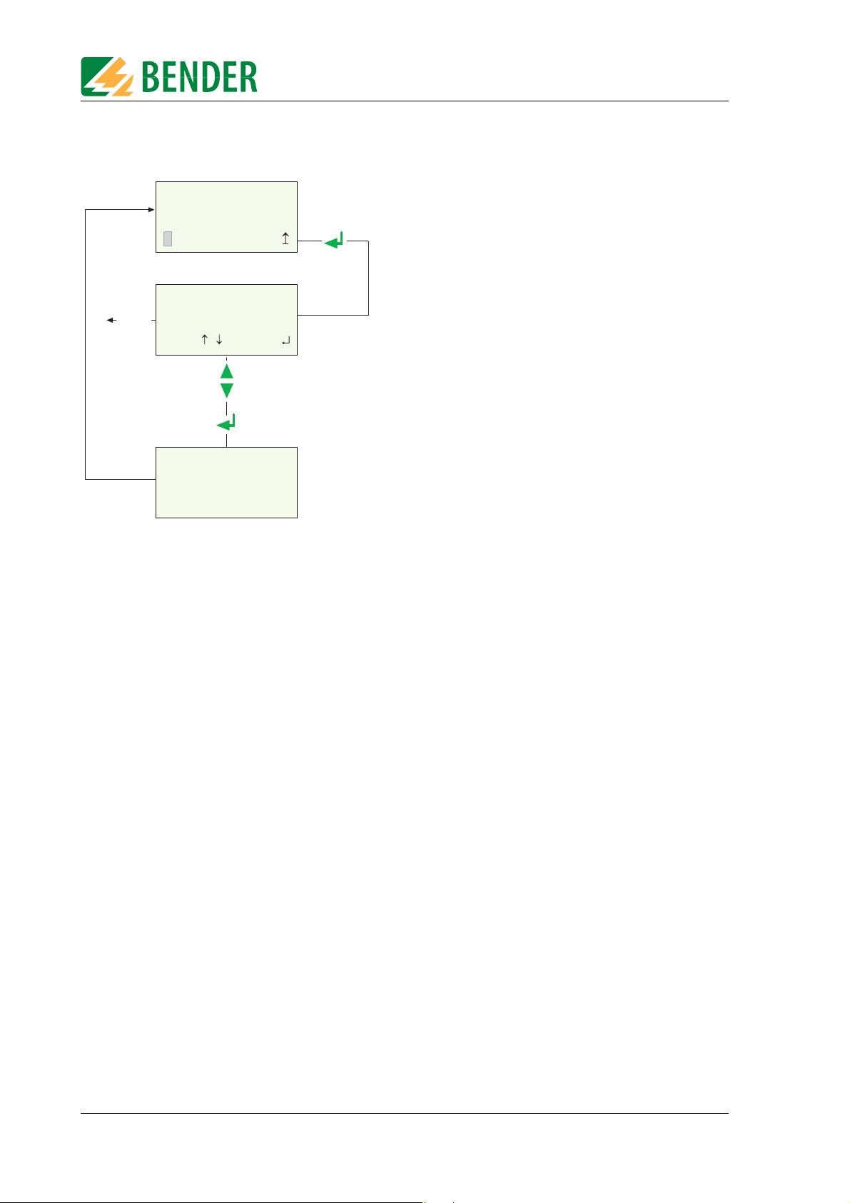
To delete the name of a test engineer:
1. Call up “Delete test eng.”
function
2. Use the arrow keys to select
the test engineer
3. Confirm with ENTER key
Confirmation is displayed
for approx. 3 seconds
The selected test
eng. will be deleted
from the catalogue.
Please wait!
1. Exit
2. Select test eng.
3. Enter new test eng
4. Delete test eng.
SELECT TEST ENGINEER
Test engin.: ( 3/ 4)
PETER MILLER
Select: , Confirm:
ESC
Operation and configuration
18
TGH1365en/10.2012
Page 19
Operation and configuration
Main menu
1. Select “Device setting”
ESC
2. Select required function
1. Exit
2. Test probe calibr.
3. Device type query
4. Warm-up/cool-down
2. Device catalogue
3. Single test
4. Test eng. catalog.
5. Device setting
4.5 Device settings
Some of the following settings are used in generating reports to record the test
results. You should therefore check these settings before carrying out the first test.
Menu item Function Page
1. Exit Returns to the main menu
2. Test probe calibration Zero calibration test probe
3. Device type query This is where you determine whether another device type
is to be queried and stored in addition to the device ID.
4. Warm-up/cool-down Setting for devices which require a warm-up period before
the test and cool-down period after the test.
5. Change comp. name The company name entered here will appear on the
printout of the test report and after switching on the
device on line 4 of the welcome menu.
6. Time/date Set system time and date
7. RS-232 parameters Set data transfer speed
8. Buzzer On/Off Switch buzzer on or off
9. Summer/wintertime Automatic switchover from summer time to winter time
10. Language/Sprache Select German or English for user menus and protocol
text. Activate settings for use in Austria.
11. Firmware update Load new version of operating software
-
20
21
21
22
22
23
24
24
25
25
To access the device settings:
TGH1365en/10.2012
19
Page 20

Operation and configuration
4.5.1 Test probe calibration
Zero balance must be carried out for the UNIMET® 300ST test probe. As with an ohmmeter, this ensures that the ohmic resistance of the test probe will not affect the PE conductor test result.
Recalibrate each time after connecting
– another test probe,
– another measuring lead,
– or a three-phase adapter
to the test system.
Proceed as follows to calibrate the test probe:
ESC
1. Exit
2. Test probe calibr.
3. Device type query
4. Warm-up/cool-down
*** CALIBRATION ***
Insert test probe
and contact PE of
socket outl. Next:
Device setting
1.Select “Test probe calibr.”
2. Hold the test probe on the earth contact
of the test socket
*)
.
Make sure that the test probe
remains there during the entire
calibration process.
3. Start calibration.
*** CALIBRATION ***
Testprobe/Cable
Please wait !
*)
With permanently connected Protection class I devices or extension cables also, the low resistance continuity of the PE conductor can be tested. The measurement is carried out between the test probe and the measuring lead connected to
the yellow socket E.
Before the test, a single zero calibration must be carried out with the test probe
and the measuring lead.
Carry out a zero calibration again if you want to run the PE conductor test with
the test probe on equipment with Schuko plug.
Failure to follow these instructions may lead to false test results.
20
TGH1365en/10.2012
Page 21

Operation and configuration
Device setting
1.Select “Warm-up/cool-down”
2. “Off” - not hot or cooling-off phase
“On” - After switching on the device
under test warm-up phase, before
switching off the device under test
cooling-off phase.
1. Exit
2. Warm-up/cool-down
period: On
1. Exit
2. Test probe calibr.
3. Device type query
4. Warm-up/cool-down
ESC
4.5.2 Device type query
Test results are often stored in the PC software. If the device to be tested is to be sorted in the
software according to type, the type name can be entered in the UNIMET when carrying out the test.
In this case, select "Device type query: On". The setting applies until it is changed again.
1. Exit
2. Test probe calibr.
ESC
3. Device type query
4. Warm-up/cool-down
1. Exit
2. Device type: Off
Enter device type
before entering ID
1.Select “Device type query”
2. The following is asked when saving a test:
"Off" - device ID only
"On" - device ID and device type
4.5.3 Warm-up and cool-down period
Once they have been switched on, an increasing number of DUTs need to complete a self-test and
warm-up period, followed by a cool-down period prior to shutting down. Examples include computers, processor-controlled devices and laser equipment. For these devices, the UNIMET® ST may only
start the measurements once the DUT has warmed up or "booted up". Otherwise, there is a risk that
the parts of the device to be tested will only have switched on partially or not at all, and therefore
will not be tested.
Once the measurements are complete, the UNIMET may only shut down the DUT once it has shut
down or cooled down. Otherwise, on laser equipment, there is the risk of overheating or, on a computer, of sectors of the hard disk becoming unusable.
Device setting
Select "Warm-up/cool-down period: On".
The settings selected for the "Warm-up/cool-down period" applies to all devices
under test for which the test has been put in operation. The settings remains until
it has been changed again.
TGH1365en/10.2012
21
Page 22

Operation and configuration
4.5.4 Changing the company name
The company name must consist of no more than 20 characters. It is printed as a header on the test
report.
2. Test probe calibr.
3. Device type query
4. Warm-up/cool-down
5. Change comp. name
ENTER COMPANY NAME:
ESC
MEIER GMBH&CO.KG
Char.: A-Z, 0-9, &-. /
Exit: ESC Next:
4.5.5 Time/date
Proceed as follows to set the time and date:
Device setting
1.Select “Change comp. name”
2. Use the arrow keys to change the first
characters and then press the ENTER key
3. Select all the remaining characters also
Briefly press the ESC key
= edit previous characters
Press and hold down the ESC key
= Exit menu without making changes
4. After entering the last character or
holding down ENTER key for
approx. 3 seconds, the entry is saved
and the settings menu exited.
The new company name is saved.
3. Device type query
4. Warm-up/cool-down
5. Change comp. name
6. Time/date
1. Exit
ESC
ESC
The UNIMET
2. Time: 14: 49
3. Date: 30. 09. 11
(Summer time/CEST)
1. Exit
2. Time: 14: 49
3. Date: 30. 09. 11
(Summer time/CEST)
®
300ST clock is powered by a battery with a service life of approximately four years (see
also chapter "6.2 Changing the battery").
Device setting
1. Select “Time/date”
2. Select “Time”
3. Use the arrow keys to select hours and
then confirm with the ENTER key
4.Use the arrow keys to select minutes and
then confirm with the ENTER key
5. Set the “Date” in the same way
22
TGH1365en/10.2012
Page 23

Operation and configuration
On the submenu 7 (see chapter "4.5.8 Summer time/winter time") you can also set whether the
switchover from summer time to winter time is to be automatic. If the note on the 4th line of the
"Time/Date" setting refers to the current date: If the automatic switchover is enabled and the following appears during the summer: 'Summer/ CEST' and during the winter 'Wintert/CET'.
CEST = Central European Summer Time
CET = Central European Time
4.5.6 RS-232 parameters
The UNIMET® 300ST can be connected to a PC via the RS-232 interface. The baud rate gives the data
transfer rate in bits per second.
The baud rate on the test system and the PC (or in the PC software) must always
be set to the same value! Data transfer can only be performed if the two settings
match.
Proceed as follows to adjust the parameters of the RS-232 interface:
Device setting
1. Select “RS-232 parameters”
2. Select the “Baud rate” setting
3. Use the arrow keys to set baud rate
and then confirm with the ENTER key
ESC
ESC
4. Warm-up/cool-down
5. Change comp. name
6. Time/date
7. RS-232 parameters
1. Exit
2. Baud rate: 9600
1. Exit
2. Baud rate: 9600
The following baud rates are available for the setting: 9600, 19200, 38400, 57600 baud
The other parameters of the RS-232 interface are fixed as follows:
Data bit 7
Stop bit 1
Parity even
TGH1365en/10.2012
23
Page 24

Operation and configuration
Caution
Device setting
1. Select “Buzzer On/Off”
2. Select setting for “Buzzer”
1. Exit
2. Buzzer: On
5. Change comp. name
6. Time/date
7. RS-232 parameters
8. Buzzer On/Off
ESC
Device setting
1. Select “Summer/wintertime”
3. Select “On” or “Off”
2. Select “Auto. switchover
from summer to winter
time”
1. Exit
2. Auto. switchover
from summer to
winter time: On
1. Exit
2. Auto. switchover
from summer to
winter time: On
6. Time/date
7. RS-232 parameters
8. Buzzer On/Off
9. Summer/wintertime
ESC
ESC
The interface cable supplied (null modem cable or USB1.1-RS-232 converter) is required for the data
transfer. The data transfer is always initiated by the PC software. No operation is required on the test
system for this to happen. For further information, please see the instruction manual for the PC
software.
The data transfer may not start if just one measurement or single test is carried
out.
Failure to observe this requirement may damage the UNIMET
®
300ST and any de-
vice under test connected to it.
4.5.7 Buzzer On/Off
Proceed as follows to turn the UNIMET® 300ST buzzer on or off:
4.5.8 Summer time/winter time
Proceed as follows to select whether the switchover from summer time to winter time should occur
automatically:
Automatic switchover from summer time to winter time applies to most European countries
(exceptions are e.g. England). Turn off the automatic switchover when using the test system in areas
where this time change does not apply.
24
TGH1365en/10.2012
Page 25

Operation and configuration
1.Select “Language/Sprache”
2. Select German or English.
German (Austria) is required for use in Austria
Standards then appear in Austrian spelling
on the display and the printout.
Device setting
1. Exit
2. German/Deutsch
3. English/Englisch
4. German(Austria)
7. RS-232 parameters
8. Buzzer On/Off
9. Summer/wintertime
10. Language/Sprache
ESC
4.5.9 Language/Sprache
User menus and printouts of the test report ma y be in Ger ma n or Engl is h. Proce ed as foll ow s to sele ct
the language:
4.5.10 Firmware update
UNIMET® 300ST is controlled by an operating software (firmware). New versions are available online
at www.bentron.de. The update is provided as a file with the extension ".hex".
To transfer the updates from the PC to the UNIMET, you will need the PC software
UNIData300.
To prepare the update:
1. UNIData300 is on the CD supplied with the device. It is designed to operate on PCs with
2. Copy the update file (e.g. UPD162 Vxxx.hex) to the hard drive of your PC.
3. Connect the interface cable supplied for data transfer (null-modem cable or USB1.1-RS-232
An update will not delete data saved in the device catalogue. However, we
strongly recommend making a backup copy before updating the device
catalogue on a PC! Other information is available in the chapter "Backing up the
device catalogue" on page 43.
From version 3.00 onwards, UNIMET® 300ST devices are equipped with a new
hardware. When trying to install the operating software 3.00 on an older device,
it cancels the update.
Windows
®
2000 (with Service Pack 3) or higher.
– If the version of the program on your PC is older, first uninstall the older UNIData300 version.
– Open the folder UNIData300 and install the software by executing the file
"UNIData300_Vxxx.exe" on your PC.
converter) to the PC and UNIMET
®
300ST.
TGH1365en/10.2012
25
Page 26

Operation and configuration
Proceed as follows to carry out the update:
1. Start the UNIData300 software ("Start -> Program -> UNIMET®300ST -> UNIData300").
2. Select "Extras -> Firmware-Update UNIMET".
3. Click on the icon (Open folder) to select the update file.
4. Select the update file "UPD162 Vxxx.hex" and click on "Open".
26
TGH1365en/10.2012
Page 27

Operation and configuration
Caution
5. Information must be read from the UNIMET for the update. Click on "Read parameters" button:
6. The information read out is displayed (device info). Click on the "Update program" button. The
UNIMET flash memory is deleted, re-programmed and then checked (verified). The progress of
the update is displayed.
7. Wait until the update is finished. UNIMET restarts and then displays the main menu.
TGH1365en/10.2012
The data transfer takes about 3 minutes. Allow the data transfer to complete
undisturbed. If the data transfer is interrupted, UNIMET
®
300ST no longer has any
operational operating software. The device must then receive a new operating
software from Bender for installation.
UNIData300 confirms that the update has been successful with the following message:
27
Page 28

4.6 Information
Main menu
1. Select “Info”
2. The test system then gives information about:
- its device name (in this case, Unimet300ST)
- the version of the internal operating software
- and its serial number
1.Exit
Device:UNIMET300ST
SW: V3.33/05.10.11
Ser-no.: 0123456789
3. Single test
4. Test eng. catalog.
5. Device setting
6. Info
ESC
The menu item "Info" on the main menu gives you the following information:
Operation and configuration
28
TGH1365en/10.2012
Page 29

5. Testing and measuring
Main menu
1. Select “Classification”
2. Select the applicable test standard
e.g. "VDE0701-0702".
3. Select appropriate device type
and safety class,
e.g. “Class I”.
4. Select applicable cable length,
e.g. “Cable length <= 5 m”
5. Select appropriate device type,
e.g. “Standard equipment”.
Next to following page.
1. Exit
2. IEC62353:2007-05
3. VDE0701-0702:08-06
1. Exit
2. Class I
3. Class II
4. Class III
5. 3ph devices CI
6. 3ph devices CII
7. Extension cable
1. Exit
2. Cable length <=5mtr
3. Cable length > 5mtr
1. Exit
2. Standard equipment
3. EE w. heat. circ.
4. EE perm. installed
1. Classification
2. Device catalogue
3. Single test
4. Test eng. catalog
ESC
ESC
ESC
ESC
5.1 Testing via classification
5.1.1 Classification
Answer the questions that appear on the screen. The test system will identify the required tests and
limits to be observed. The guided test sequence will guide you through all the necessary steps to be
taken. In addition to electrical tests, the test sequence also contains a visual and functional test.
Example 1:
Classification of electrical equipment (e.g. angle grinders) according to DIN VDE 0701-0702 with the
UNIMET
®
300ST:
TGH1365en/10.2012
29
Page 30

Testing and measuring
6. Select the measurement method
for determining the leakage current,
e.g. “Direct measurement”.
7. Select other settings for the test.
Label selected setting with “
”.
Then select menu item “5. Next”
and confirm with the ENTER key.
1. Exit
2. Direct measurement
3. Differential meas.
4. Alternative meas.
1. Exit
2.
R-ISO ?
3. Disconn.not poss.
4.
Conduct.parts->PE
5. Next
ESC
ESC
8. Select automatic or manual test
1. Exit
2. Test automatic
3. Test manual
ESC
R-ISO?
(Carry out R-ISO?)
During insulation measurement, a voltage of 500 V is applied between
the active conductor and earth. Insulation testing may damage sensitive
devices. Only activate insulation measurement if permitted by the
manufacturer's instructions provided with the DUT.
Note: If the setting "Disconn. not poss." is selected, the insulation
measurement cannot be selected.
Disconnection not
Choose this setting if the device cannot be disconnected from the mains.
possible
Conduct. parts >PE All accessible conductive parts are connected to PE. This setting can be
used if you know that all metal accessible parts of the enclosure are
connected to the PE conductor. During device testing, the test probe then
only has to be brought into contact with one metal point on the
enclosure.
If not all metal parts of the enclosure are connected to PE, deactivate this
function. During device testing, an additional equipment leakage current
test resp. touch current test (Class II) is carried out. In this case, the manual
test will be selected automatically.
During device testing, proceed as follows:
During PE conductor testing, use the test probe to scan all parts of the
enclosure connected to PE. During equipment leakage current testing or
touch current testing (Class II), test all parts not connected to PE.
30
TGH1365en/10.2012
Page 31

Testing and measuring
Main menu
1. Select “Classification”
2. Select test standard
"IEC62353:2007-05".
3. Select applicable test,
e.g. “Hosp.bed test CI”.
4. Select automatic or manual test.
1. Exit
2. Hosp.bed test CI
3. Hosp.bed test CII
4. Class I
5. Class II
6. Class III
7. 3Ph devices Cl
8. 3Ph devices ClI
1. Exit
2. IEC62353:2007-05
3. VDE0701-0702:08-06
1. Exit
2. Test automatic
3. Test manual
1. Classification
2. Device catalogue
3. Single test
4. Test eng. catalog
ESC
ESC
ESC
R-PE
Value: 0.004
Ω
Limit: 0.300 Ω
Repeat: Next:
Example 2:
Classification of an electric hospital or care bed with the UNIMET
®
300ST:
Manual or automatic test
The test sequence can be carried out automatically or manually for each device under test.
Automatic testing
During automatic testing, the test probe or test terminal comes into contact with one point of the
DUT. The test sequence then runs through all the test steps automatically.
Manual testing
During manual testing, it is possible to repeat each test step as often as required and bring the test
probe into contact with a number of accessible parts on the DUT consecutively.
UNIMET
the PE conductor resistance, this is the highest measured value; when measuring the insulation
resistance, this is the lowest measured value.
®
300ST saves the "worst" measurement in each case. When measuring leakage currents and
TGH1365en/10.2012
31
Page 32

Testing and measuring
R-ISO CI
Value: 200.97 M
Ω
Limit: 2.00 MΩ
--- Measuring ---
R-ISO CI
Value: 200.97 M
Ω
Limit: 2.00 MΩ
Next:
Manual testing of hospital and care beds (UNIMET® 300ST)
The manual test is basically carried out the same way. However, manual measurements where the
bed is in operation (e.g. leakage currents) and the measuring of the insulation resistance are
different. These measurements are carried out as follows:
With leakage currents, the supply voltage to the bed is uninterrupted; with the insulation meas-
urement, the measuring voltage is uninterrupted.
With the measurement where the bed is supplied with voltage, the head and footboard are
operated along with other electrically actuated adjustment devices. The adjustment devices
are operated until their limit switch responds.
Various accessible metal parts of the bed can be scanned with the test probe.
The measurement is repeated until the ENTER button " " is pressed.
In this way, changes in the measured values caused by operating the adjustment devices on the bed
are reliably detected.
The display alternates as follows:
32
TGH1365en/10.2012
Page 33

Testing and measuring
Caution
Caution
Caution
Caution
Caution
5.1.2 Tests
The test system must not be used for testing electrical installations. It is exclusively intended for testing devices and systems listed under "System description" on
page 9.
During insulation measurements, a direct current of 500 V is applied. Touching
faulty DUTs when the test probe is in direct contact may expose personnel to the
danger of electric shock. The touch current is limited to 2.5 mA. .
During alternative measurements of the leakage current, an alternating current
of 250 V is applied. Touching faulty DUTs when the test probe is in direct contact
may expose personnel to the danger of electric shock. The test current is limited
to 3.5 mA.
The current flowing on faulty DUTs during a test may cause unwanted tripping
of a residual current protective device (RCD).
For testing equipment leakage currents with equipment in operational condition, the device under test must be installed in an insulated state to prevent leakage currents from flowing via accidental earth connections.
Exposed conductive parts and the measuring leads of the device under test may
be live and therefore must not be touched.
TGH1365en/10.2012
33
Page 34

Testing and measuring
E
LNPE
Device
under test
Connect the DUT to the test system.
1. To connect hospital beds, care beds and electrical equipment using a plug-in connector:
2. Connecting single-phase permanently installed equipment to the test system
– Switch off the power to the device
– Disconnect the power supply connection.
34
TGH1365en/10.2012
Page 35

Testing and measuring
3. Testing the extension cables
- Connect connecting cables and extensions as follows:
TGH1365en/10.2012
35
Page 36

Follow the instructions on the UNIMET® 300ST display:
Testing and measuring
VISUAL INSP. ERROR
Continue test
anyway?
Cancel:ESC Next:
ESC
The test results
are evaluated
ESC
ESC
not passed
** Note **
Connect DUT to
Unimet a. switch on!
Start:
VISUAL INSPECTION
1. Passed
2. Failed
R-PE
Value: 0.004
Limit: 0.300 Ω
- - - Measuring - - -
Start the electrical tests
Ω
1. Connect device under test
then start test
2. Carry out
and evaluate
visual inspection
3. If visual inspection
not passed:
decide whether
passed
the test should
proceed anyway
During the PE conductor test, the low-resistance continuity of the PE conductor
is tested with a high current (> 2 A). This produces heat energy.
If the PE conductor test is repeated very often and without breaks during manual
testing or single tests, the test system will prevent overheating by aborting the
test. A message will appear:
**Danger**
Test will be stopped
Transformer overheat
(Measur. Time > 2 min)
After the test is terminated, testing the PE conductor is permitted again within a
few seconds.
36
TGH1365en/10.2012
Page 37

Testing and measuring
After the visual inspection, the following tests are carried out for the "Hosp. bed test CI" example:
** WARNING **
Load current <= 5 mA
DUT switched on?
Next:
R-PE
Value: 0.004
Limit: 0.300 Ω
- - - Measuring - - -
R-ISO CI
Value: > 300.00 M
Limit: 2.00 MΩ
- - - Measuring - - -
** ATTENTION! **
Mains voltage at the
socket outlet
Next:
LOAD CURRENT
Value : 25 mA
Limit: --------
- - - Measuring - - -
Ω
yes
Load current
< 5 mA ?
no
Ω
4. Confirm message
If applicable:
Switch on device and
then press ENTER key
Please note that only DUTs with a power consumption of up to 3700 VA may be supplied
with power via the UNIMET® 300ST test socket. If DUTs with higher power consumptions
are connected, the thermomagnetic circuit-breaker integrated into the UNIMET® 300ST
power switch will trip. Once the DUT has been removed, the test system can be switched
on after a few seconds.
MAINS VOLTAGE
Value: 230 V
Limit: --------
- - - Measuring - - -
POWER CONSUMPTION
Value: 6 VA
Limit: --------
- - - Measuring - - -
The leakage current test is carried out
TGH1365en/10.2012
37
Page 38

Testing and measuring
WARM-UP PERIOD:
Boot up DUT!
Next:
COOL-DOWN PERIOD:
Shut down DUT!
Next:
Test sequence with warm-up and cool-down period
If "warm-up and cool-down period" is activated on the device settings, UNIMET waits until the DUT
is powered up or ready for operation. Once the DUT has been connected to the mains supply, the
following message appears:
Wait until the DUT is powered up and then confirm by pressing the ENTER button " ".
After the last test step carried out at this phase position, UNIMET will wait for the DUT to shut down.
Wait until the DUT is powered down and then confirm by pressing the ENTER button " ".
With all test sequences which put the DUT into operation, a test is carried out with the phase position
reversed. In this case, the DUT is powered up and powered down one more time.
38
TGH1365en/10.2012
Page 39

Testing and measuring
** ATTENTION! **
Limit for R-PE
exeeded!
Abort: ESC Repeat:
** Danger! **
Leak.current > 20 mA
Test finished
Continue:
¿
Now, the leakage current test is carried out:
I-ELC CI Diff.
Value: 0.04 mA
Limit: 0.50 mA
- - - Measuring - - -
I-ELC CI Diff. Ph-r
Value: 0.04 mA
Limit: 0.50 mA
- - - Measuring - - -
The function test is carried out
Checking the limits
UNIMET
®
300ST monitors whether the limits are kept to throughout the test sequence.
If a limit is violated when measuring the PE conductor resistance, the test engineer can decide
whether to abort the test or continue to its completion:
With all the other measurements during which the limit has not been kept to, the test is continued.
However, the test system does not permit any hazardous currents:
Faulty DUTs can exhibit dangerous leakage currents. During all leakage current
measurements, testing is aborted immediately if a measured value >20 mA is
reached. UNIMET
®
300ST then shows:
TGH1365en/10.2012
39
Page 40

Testing and measuring
ESC
Save,
Print,
Save and print
ESC short = Edit previous characters
ESC long = Exit menu without making change
short = Accept characters
long = Accept result, carry out
selected action and exit menu
ENTER DEVICE-ID:
Char.: A-Z,0-9,-, /
Exit:ESC Next:
TEST-RESULTS
Total result:
PASSED
Select: , Cont.:
View
result
Discard
test
,
= select next or previous test step
= back to previous menu
1. Save
2. Print
3. Save and print
4. View result
5. Cancel test
On completion of the test sequence, the functional test is carried out. Here, the DUT is put into
operation via the test socket on the test system.
5. Start function test and
then evaluate result
passed
Volt. at sock.outlet
***************************
TEST NOT PASSED!
***************************
Next:
not passed
Message appears when
at least one test step
has not been passed.
5.1.3 Evaluating the test result
FUNCTIONAL TEST
1. Passed
2. Failed
3. Start Funct. test
1. Save
2. Print
3. Save and print
4. View result
5. Cancel test
All
test steps
no
***************************
***************************
Next:
passed
?
TEST PASSED!
6. Evaluate test result
yes
If "Device type query" in the device settings is enabled, this is entered before the device ID.
40
TGH1365en/10.2012
Page 41

Testing and measuring
5.2 Recurrent test and device catalogue
The test results, tests and limits of the device tested by UNIMET® 300ST can be stored in the device
catalogue. In the case of recurrent tests, the devices are simply called up in the device catalogue and
tested again. Other functions are print report, display results, delete device or delete entire catalogue.
The content of the device catalogue can be transferred to a PC program. Similarly, data records selected in the PC program can be transferred to the device catalogue. These functions are described
in the PC software guide.
Proceed as follows to use the device catalogue:
1. Classification
2. Device catalogue
3. Single test
4. Test eng. catalog
Main menu
1. Select “Device catalogue”
Test device
1. Exit
2. Select device
3. Collective print
4. Delete catalogue
----- ID SELECTION -----
ID: ( 1/ 5)
ESC
XY47123456
Select: , Confirm:
ESC
1. Exit
2. Test device
3. Print test report
4. View result
5. Delete device
6. Change dev. type
2. Select required function:
- Select device
- Print out all test logs
- Delete catalog:
after the prompt, all entries
are deleted
3. Select ID No.
,
select next or previous device
Confirm selection
( 1/ 5)
*1
*2
View resultsPrint test report Delete device
shows the position
in the memory and
the number of devices
4. Select action
Unimet a. switch on!
Start:
*1 If "device type query" in the device settings is enabled, then the device type is displayed
*2 If "device type query" in the device settings is enabled, an additional menu item "Change
TGH1365en/10.2012
** Note **
Connect DUT to
Test starts
Test results
are printed
Please wait !
TEST-RESULTS
Total result:
PASS
Select: , Cont.:
,
select next
or previous
test step
back to
previous menu
The selected ID
will be deleted from
the catalogue
Please wait !
on the last line for approximately 2 seconds when scrolling in the device catalogue.
device type" will also appear.
41
Page 42

Testing and measuring
5.2.1 Collective printout
Each DUT stored in the test system can be printed out as a measurement report. Select either all the
reports or only the reports for a desired period.
ESC
ESC
1. Exit
2. Select device
3. Collective print
4. Delete catalogue
1. Exit
2. All data records
3. Select by date
1. Exit
2. All data records
3. Select by date
01.01.10--31.12.10
Device catalogue
1. Select “Collective print”
2. Select required function:
- Print out all test records
- Select the period from which
the test log is printed.
3. The first number for changing the period
(from-to) flashes.
Set the relevant day, month and year
for the start and end of the period as follows
- Use the arrow keys to select number (start day)
and then confirm with the ENTER key
- the next place flashes. Use the arrow keys
to select number (start month) and then
confirm with the ENTER key
- Also change all remaining numbers
ESC
Collective print
Data record 1 / 10
Abord: ESC
The printout starts when the last number
(last month) has been confirmed with ENTER
4. The data records for the selected period are
printed out.
The printout can be aborted with the ESC key.
42
TGH1365en/10.2012
Page 43

Testing and measuring
5.2.2 Backing up the device catalogue
The device catalogue contains the ID numbers, the test results and the classification of tested
devices for the recurrent test. These data can be backed up on a PC with the Bender-PC software
UNIData300.
Proceed as follows to start UNIData300:
1. UNIData300 is on the CD supplied with the device. It is designed to operate on PCs with
Windows
– If the version of the program on your PC is older, first uninstall the older UNIData300 version.
– Open the folder UNIData300 and install the software by executing the file
"UNIData300_Vxxx.exe" on your PC.
2. Connect the interface cable supplied for the data transfer (null-modem cable or USB1.1-RS-232
converter) to the PC and UNIMET
3. Switch on UNIMET.
4. Start the UNIData300 software ("Start -> Program -> UNIMET
UNIData300 adapts itself to the required interface (e.g. COM1) and to the baud rate set on the
UNIMET. The settings for imports and exports appear at the bottom edge of the screen.
The following pages provide a brief introduction to the software UNIData300.
The UNIData300 software Help menu provides a detailed description.
®
2000 (with Service Pack 3) or higher.
®
300ST.
®
300ST -> UNIData300").
To import data to the PC:
1. Select "Data" -> "Import" to import the data from the UNIMET to the PC software
UNIData300 reports when the data have been imported successfully:
TGH1365en/10.2012
43
Page 44

2. Now select the data to be saved in the UNIData300 device database.
1
2
3
4
Testing and measuring
1 Select the data to be stored:
- Click on the individual data in the left window, or
- Select according to test standard and enable the import filter. Once all the standards
are activated, all the data will be selected for saving.
2 Decide whether the device catalogue in the UNIMET is to be deleted.
3 Start the import. UNIData300 shows the progress of data transfer.
Wait until the data are stored.
4Close the Import window.
44
TGH1365en/10.2012
Page 45

Testing and measuring
1
4
3
2
5
6
7
To use the data read in on the PC:
Select "Device catalogue" -> "Open".
The device catalogue data stored on the PC are displayed:
The following functions are available:
1 Use the arrow buttons to select a device. All the known data for this device will be displayed.
Only the fields "Test interval (months)" and "Device name/type" can be changed.
2 After clicking on this tab, you will see the results for the current device.
3 Enter a test interval. This allows you (after updating) to select the devices to export which are
due for testing.
4 "Update" accepts your entries in the fields "Device name/type" and "Test interval (months)" in
the device database. Once the field "Test interval (months)" is full, UNIData300 updates the
field "Next test".
5 The current device is deleted.
TGH1365en/10.2012
45
Page 46

6 A print preview will appear:
-Click on to print.
-Click on to export the test report.
Formats: PDF, MS-Word, Excel, RTF, HTML 4.0.
-In the menu "Extra -> Protocol settings", you can enter the company name (4 lines max.)
and insert the company logo for the report.
7 Click on "Close" to leave the Program window.
Testing and measuring
To delete the device database of UNIData300:
Select "Device catalogue" -> "Delete".
Confirm the confirmation prompt "Delete all". The device database of UNIData300 will be deleted.
To export data from the PC to UNIMET:
1. Select "Data" -> "Export" to transfer the data stored in the PC software to the device catalogue
of the UNIMET.
UNIData300 makes the stored data available and reports:
46
TGH1365en/10.2012
Page 47

Testing and measuring
1
2
3
4
2. Now select the data to be exported. Select the individual data or click on "Select all". Export the
selected data with "Start export".
1 Select the data to be exported:
- Click on the individual data in the left window, or
- Select according to test standard and enable the export filter.
2 If all the data are to be exported, just click on "Select All".
3
4 Close the Export window.
Start the export. UNIData300 shows the progress of data transfer.
Wait until the data are transferred.
TGH1365en/10.2012
47
Page 48

Testing and measuring
To end UNIData300:
Select "Device catalogue"-> "Exit".
To save a copy of the device database of UNIData300:
The menu "Extra -> Database utilities -> Backup database" enables you to back up the database on
the hard drive of your PC.
The copy of the database can be found in the folder "C:\Documents and Settings\All
Users\Application Data\UNIData300\DB_BACKUP".
To back up the original device database of UNIData300:
The hard disk of the PC is not an absolutely secure storage location for data. With a backup copy of
the device database, you will avoid loss of data.
The original device database "u300.mdb_xx" can be found in the folder "C:\Documents and
Settings\All Users\Application Data\UNIData300\Database". Regularly backup the device database
on another data medium.
48
TGH1365en/10.2012
Page 49

Testing and measuring
**Danger**
Test will be stopped
Transformer overheat
(Measur. Time > 2 min)
5.3 Single test
Test steps can be called up in the form of single tests and repeated as often as required. For example, if a limit
value is not complied with during a classified test sequence, the test step concerned can be examined in more
detail using a single test.
ESC
1. Classification
2. Device catalogue
3. Single test
4. Test eng. catalog
1. Exit
2. Mains volt. #081
3. Load current #080
4. Power cons. #082
5. R-PE #003
6. R-PE perm.c. #003
7. R-ISO
8. I-ELC A
9. I-PE
10. I-TC
11. I-ELC CI
12. I-ELC CII
Main menu
1. Select “Single test”
2. Select required measurement
ESC
ESC
Option I-ELC CI
1. Direct #210
2. Direct Ph-r #211
3. Diff. meas. #212
4. Diff. Ph-r #213
5. Diff. 3Ph #078
6. Exit
3. Select details for measurement
(e.g. phase position when measuring
device leakage, PE conductor
and touch current)
4. Read off measured value
---- SINGLE TEST----I-ELC CI Direct
Meas. value: 0,04 mA
-- Abort: ESC --
During the PE conductor test, the low-resistance continuity of the PE conductor
is tested with a high current (>2 A). This produces heat energy.
If the PE conductor test is repeated very often and without breaks during manual
testing or single tests, the test system will prevent overheating by aborting the
test. A message will appear:
TGH1365en/10.2012
After the test is terminated, testing the PE conductor is permitted again within a
few seconds.
49
Page 50

Testing and measuring
50
TGH1365en/10.2012
Page 51

6. Maintenance and calibration
** Battery flat! **
Change the battery
Set time/date
Next:
** ERROR **
xxxxx
Contact Service!
Next:
6.1 Calibration
Like any other test instrument, the UNIMET® 300ST requires a regular measured values check. The
calibration interval is 36 months. The test system can only be calibrated and adjusted by Bender or
a centre approved by Bender.
6.2 Changing the battery
The UNIMET® 300ST clock is powered by a battery with a battery life of approximately four years (see
also chapter "4.5.5 Time/date"). If the battery voltage is too low, the following message appears after
switching on the test system:
The test system battery can only be changed by Bender or a centre approved by Bender.
The battery is always replaced by Bender as part of the calibration procedure.
6.3 Error messages
The UNIMET® 300ST continuously monitors its device functions. In the unlikely event on an error
occurring, a message will appear on the display:
xxxxxx stands for the type of error given out. There are the following different types of errors:
Type of fault Meaning
I2C bus (Code 002) Hardware error internal bus
RT clock (Code 004) Device-real-time clock is not running
Cal. values (code 016) Errors in memory for the calibration values. In certain cases,
can be eliminated by correcting the calibration values in the
UNIMET® 300ST database
TGH1365en/10.2012
51
Page 52

Maintenance and calibration
Type of fault Meaning
Database (Code 032) This error appears when a bad data record which cannot be
corrected is detected in the device database.
The error can be eliminated if the data record where this error occurs
is deleted.
Firmware (Code 128) With a UNIMET® 300ST, the firmware of a UNIMET® 301ST has been
installed or vice versa
If several errors occur simultaneously, a different error code is given out.
Proceed as follows:
1. Shut down the UNIMET® 300ST and remove the mains connector.
2. Make a note of what happened prior to the error: operator inputs, type of DUT, ambient
conditions etc.
3. Keep the device serial number to hand.
4. Call Bender technical support and describe the type of error and the error code.
6.4 Disposal
Abide by the national regulations and laws governing the disposal of this device. Ask your supplier
if you are not sure how to dispose of the old equipment.
Directive 2002/96/EG on waste electrical and electronic equipment and Directive 2002/95/EG on the
restriction of certain hazardous substances in electrical and electronic equipment apply in the European Community.
In Germany, these policies are implemented through the "Electrical and Electronic Equipment Act"
of 16 March 2005. According to this, the following applies:
Electric and electronic equipment are not to be included in household waste. This is indicated
by the symbol:
Batteries and accumulators are not to be included in household waste but must be disposed of
in accordance with the regulations.
Old electrical and electronic equipment (WEEE) from users other than private households
which was introduced to the market after 13th August 2005 must be taken back by the manufacturer and disposed of properly.
52
TGH1365en/10.2012
Page 53

7. Data
7.1 Standards
7.1.1 Application standards
The UNIMET® 300ST carries out measurements and tests according to the following standards:
DIN EN 62353 (VDE 0751-1):2008-08
DIN VDE 0701-0702 (VDE 0701-0702):2008-06
7.1.2 Design standards
The requirements of the following standards were taken into account in the design of the UNIMET®
300ST:
DIN VDE 0404-1 (VDE 0404-1):2002-05
DIN VDE 0404-2 (VDE 0404-2):2002-05
DIN VDE 0404-3 (VDE 0404-3):2005-04
"Medical electrical equipment - Recurrent test and test after repair of medical electrical
equipment (IEC 62353:2007); German version EN 62353:2008"
"Inspection after repair, modification of electrical appliances - Periodic inspection on electrical
appliances - General requirements for electrical safety"
ÖVE/ÖNORM EN 62353:2009-01-01
"Medical electrical equipment - Recurrent test and test after repair of medical electrical
equipment (IEC 62353:2007)"
"Testing and measuring equipment for checking the electric safety of electric devices - Part 1:
General requirements"
"Testing and measuring equipment for checking the electric safety of electric devices - Part 2:
Testing equipment for tests after repair, change or in case of repeat tests"
"Testing and measuring equipment for testing the electrical safety of electrical devices - Part 3:
Equipment for periodical tests and tests prior to commissioning medical electrical devices or
systems"
TGH1365en/10.2012
53
Page 54

7.2 Test steps
A classified test sequence with the UNIMET® 300ST comprises a number of individual test steps. The
test steps are sorted on the basis of measurement numbers.
Data
Meas
No.
3 PE conductor resistance, permanently
4 Protective earth resistance, installed
5
6 Insulation resistance, Protection Class I R-ISO CI MOhm IEC 62353
106 Insulation resistance, Protection Class I R-ISO CI MOhm VDE 0701-0702
107
120 Insulation resistance, cable R-ISO MOhm VDE 0701-0702
44 Equipment leakage current Protection
46 Equipment leakage current -
109 Equipment leakage current Protection
Name of measurement Short text Unit Standard
R-PE Ohm VDE 0701-0702
attached cable
equipment
Insulation resistance, Protection Class II
Insulation resistance, Protection Class II
Class I - alternative measurement
Protection Class II - alternative
measurement
Class 1 -alternative measurement
R-PE Ohm VDE 0701-0702
R-ISO CII MOhm IEC 62353
R-ISO CII MOhm VDE 0701-0702
I-ELC-A CI mA IEC 62353
I-ELC-A CII mA IEC 62353
I-ELC-A CI mA VDE 0701-0702
+ IEC 62353
+ DIN EN 62353
110 Equipment leakage current Protection
Class II -alternative measurement
80 Load current measurement A VDE 0701-0702
81 Operating voltage V VDE 0701-0702
82 Power consumption kVA VDE 0701-0702
111 PE conductor current - Direct
measurement
112 PE conductor current - Direct
measurement - Phase reversed
113 PE conductor current - Differential
measurement
114 PE conductor current - Differential
measurement - Phase reversed
I-ELC-A CII mA VDE 0701-0702
+ DIN EN 62353
+ DIN EN 62353
+ DIN EN 62353
I-PE Direct mA VDE 0701-0702
I-PE Direct Ph-r mA VDE 0701-0702
I-PE Differential mA VDE 0701-0702
I-PE Differential Ph-r mA VDE 0701-0702
54
TGH1365en/10.2012
Page 55

Data
Meas
No.
76 PE conductor current - Differential
115 Touch current - Direct measurement I-TC Direct mA VDE 0701-0702
116 Touch current - Direct measurement -
117 Touch current - Differential
118 Touch current - Differential
77 Touch current - differential
210 Equipment leakage current -
211 Equipment leakage current -
Name of measurement Short text Unit Standard
I-PE Differential 3ph mA VDE 0701-0702
measurement - Three-phase
I-TC Direct Ph-r mA VDE 0701-0702
Phase reversed
I-TC Differential mA VDE 0701-0702
measurement
I-TC Diff. Ph-r mA VDE 0701-0702
measurement - Phase reversed
I-TC Diff. 3ph mA VDE 0701-0702
measurement - Three-phase current
I-ELC CI Direct mA IEC 62353
Protection Class I - Direct
measurement
I-ELC CI Dir. Ph-r mA IEC 62353
Protection Class I - Direct
measurement - Phase reversed
212 Equipment leakage current-
Protection Class I - Differential
measurement
213 Equipment leakage current -
Protection Class I - Differential
measurement - Phase reversed
78 Equipment leakage current -
Protection Class I - Differential
measurement - Three-phase current
214 Equipment leakage current -
Protection Class II - Direct
measurement
215 Equipment leakage current -
Protection Class II - Direct
measurement - Phase reversed
216 Equipment leakage current Class II -
Differential measurement
217 Equipment leakage current Class II -
Differential measurement - Phase
reversed
79 Equipment leakage current Class II -
Differential measurement - Threephase current
I-ELC CI Differential mA IEC 62353
I-ELC CI Diff. Ph-r mA IEC 62353
I-ELC CI Diff. 3ph mA IEC 62353
I-ELC CII Direct mA IEC 62353
I-ELC CII Direct Ph-r mA IEC 62353
I-ELC CII Diff. mA IEC 62353
I-ELC CII Diff. Ph-r mA IEC 62353
I-ELC CII Diff. 3ph mA IEC 62353
TGH1365en/10.2012
55
Page 56

7.3 Technical specifications
Supply voltage .............................................................................................................................................................. AC 230 V ± 10%)
Frequency range ......................................... .............................................................................................................................. 45 - 65 Hz
Power consumption ..................................................... ................................................... .......................................................max. 50 VA
Maximum load current ................................................................ ..................................................................................................... 16 A
Maximum connectable load at 230 V......................................................................................................................................... 3700 VA
Protection class ........................................................................................................................................................................................II
Ambient temperature ........................................................................................... ...................................................................0°C - 50 °C
Storage temperature ............................................................................................................................................................ -10 - +70 °C
Degree of protection............................................................................................................................................................................IP20
Testing of PE conductor resistance
Test voltage ................................................................................................................................................approx. 5 V, mains frequency
Short circuit current .........................................................................................................................................................................> 2 A
Meas. range ............................................................................................................................................................ 0.001 Ω - 29.999 Ω
Meas. accuracy ..................................................................................................................0.001Ω - 1.0 Ω: ± 2.5% of MV ± 2 digits
........................ .................................................. ................................................. .............. 1.001Ω - 29.999 Ω: ± 5% v. M. ± 2 digits
Leakage current by differential current measurement
Meas. range ............................................................................................................................................................. 0.02 mA - 19.99 mA
Meas. accuracy .................................................................................................................................................... ± 5% of MV ± 5 digits
Direct measurement of the leakage current
Meas. range ......................................................................................................................................................... 0.001 mA - 19.999 mA
Meas. accuracy ........................................................................................................... 0.001 mA - 19.999 mA: ± 5 % of MV ± 2 digits
Equivalent unit leakage current
Meas. range ......................................................................................................................................................... 0.001 mA - 19.999 mA
Meas. accuracy ............................................................................................................. 0.001 mA - 9.999 mA: ± 5 % of MV ± 2 digits
........................ .................................................. ................................................. .......10.000 mA - 19.999 mA: ± 7 % of MV ± 2 digits
Test voltage (equiv. unit leakage current) ........................................................ approx. mains voltage, mains frequency
Test current ......................................................................................................................................................max. 3.5 mA
Data
Insulation resistance
Test voltage ....................................................................................................................................................................approx. 500 V DC
Max. test current ............................................................................................................................................................................2.5 mA
Meas. range ....................................................................................................................................................... 0.01 MΩ to 299.9 MΩ
Meas. accuracy .......................................................................................................... 0.01 MΩ - 99.99 MΩ: ± 5 % of MV ± 2 digits
........................................................................................................................... 100.00 MΩ - 199.99 MΩ: ± 10 % of MV ± 2 digits
Load current measurement
Meas. range ....................................................................................................................................................................... 0.01 A to 16 A
Meas. accuracy ................................................................................................................................................ ± 2.5% of MV ± 3 digits
Voltage measurement
Meas. range ...............................................................................................................................................................................90 - 264 V
Meas. accuracy .................................................................................................................
Apparent power
Meas. range ............................................................................................................................................................................ 5 - 3700 VA
Meas. accuracy ................................................................................................................................................... ± 5 % of MV ± 5 digits
General data
Dimensions (without bag) .....................................................................................................approx. 168 x 272 x 124 mm (W x D x H)
Weight (without accessories or bag) ................................................................................................................................. approx.2.2 kg
Calibration interval: ......................................................................................................... ........................................................36 months
of MV = of measured value
............................... ± 2.5% of MV ± 2 digits
56
TGH1365en/10.2012
Page 57

Data
7.4 Ordering data
Type Comments Item no.
UNIMET® 300ST
standard
UNIMET® 300ST
CH version
VK701-6 Schuko adapter B 96020067
VK701-7 Adapter for cold devices B 96020066
RS-232/RS-232
interface cable
Test probe 3 m instrument lead with black test probe B 928748
Test terminal Test terminal black B 928741
AR100 Barcode scanner B 96020078
PS/2 Barcode pen reader B 96020082
Test system for electric sick beds and
hospital beds; tests according to
DIN EN 62353, DIN VDE 0701-0702;
Uop = AC 230 V; max. load 3500 VA;
Plug/socket: German
Test system for electric sick beds and
hospital beds; tests according to
DIN EN 62353, DIN VDE 0701-0702;
Uop = AC 230 V; max. load 3500 VA;
Plug/socket: Switzerland
Cable for connecting the test system with a
PC, 9-pin, female-female
(Null modem cable)
USB1.1 RS-232 converter B 96020086
B 96023000
B 96023001
B 96012012
Flex keyboard B 96020093
DS32A Three-phase adapter for measurement on
mobile three-phase equipment during
operation
CEE 3pol. 16 A Plug/Socket,
CEE 5pol. 32 A Plug/Socket, for
UNIMET® 1100/800/400/300ST
VK701-8 ADAPTERKIT 16A for DS32A, for
measurement on 16 A three-phase
equipment in combination with the threephase adapter DS32A
Other models and software are available on request.
B 96020098
B 96020097
TGH1365en/10.2012
57
Page 58

Data
58
TGH1365en/10.2012
Page 59

INDEX
A
Accessories 10
Areas of application
Areas of use
7
9
B
barcode reading wand 15
Barcode scanner
- Connection
Battery
- Changing
Baud rate
Buzzer
15
14
22
51
23
24
C
Calibration interval 51
Carrying bag
Circuit-breaker
Classification
Collective printout
Company name
Connecting the DUT
cool-down period
10
- thermo-magnetic
29
42
22
34
21
D
Damage in transit 7
Data transfer speed 19
22
Date
Device
- permanently installed
Device catalogue
- save
Device database
- To save backup
Device functions
Device settings
Device type query
Devices
- permanently installed
41
43
48
51
19
21
E
Equipment
- electrical 29
52
Error code
37
34
20
Error types
Extension cables
Extensions
51
20
35
F
Firmware 52
Firmware update
Functional test
25
40
H
Hospital and care beds 9
hospital and care beds
- manual testing
hospital bed
32
31
I
IBM emulation 14
Interface cable
Interfaces
IT system
25, 43
12
9
K
Keyboard 15
- Connection
14
L
Language 25
Leakage currents 9
- dangerous
29
Limits
- Checking 39
Lower case
39
15
M
Main menu 13, 16
Manufacturer's instructions
30
N
Null modem cable 24, 25, 43
null-modem cable
10
O
of the test log 22
Operating menus
Operating software
Ordering data
12
25
57
P
PC software 23, 41
PE conductor test
Personnel
Plastic enclosure
Plug-in connector
Power consumption
Principle of operation
Print protocol
12, 14
Printer
PS/2 switch cable
36, 49
7
12
34
37
14
41
14
R
Recurrent test 41
RS-232 interface
23
S
Serial number 16
Single test
Standards
Summer/winter time
Supply voltage 13
Systems
49
10, 53
- earthed
23, 24
9
T
Test engineer catalogue 16
Test engineer names
Test probe
- Others
- Zero balance
Test terminal
29
Tests
- Automatic
- Manual
22
Time
16
12
20
20
10
31
31
U
Umlauts 15
UNIData300
UniData300, installing
25, 43
43
TGH1400en/02.2012
59
Page 60

UP/DOWN keys 14
USB1.1 RS-232 converter
Use
- intended
10, 24, 25, 43
7
W
Warm-up and cool-down period 38
Warm-up period
21
INDEX
60
TGH1400en/02.2012
Page 61

Page 62

Bender GmbH & Co. KG
Londorfer Str. 65 • 35305 Grünberg • Germany
Postfach 1161 • 35301 Grünberg • Germany
Tel.: +49 6401 807-0
Fax: +49 6401 807-259
E-Mail: info@bender-de.com
Web: http://www.bender-de.com
 Loading...