

Page 1
Manual
EN
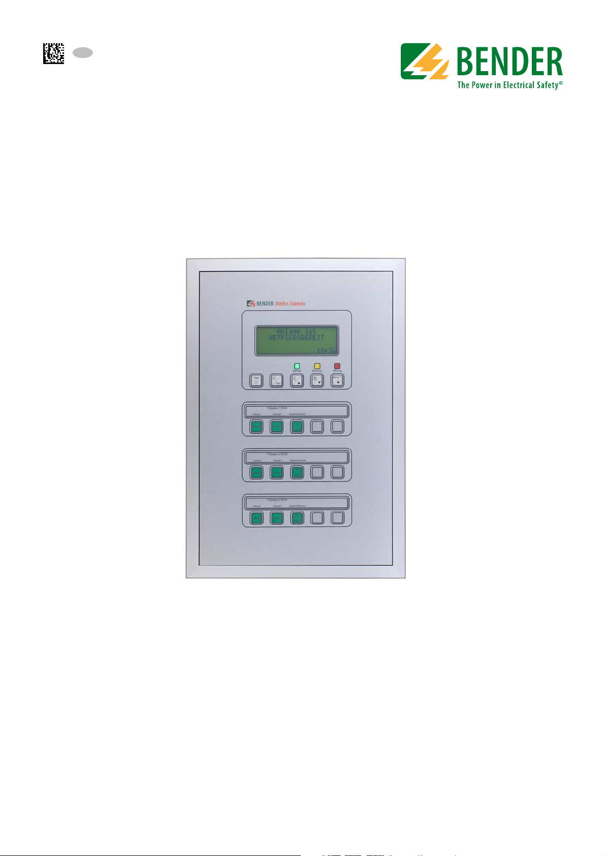
TM800
Alarm indicator and operator panel
Software version: 4.0x
TM800_D00165_00_M_XXEN/06.2015
Page 2

Bender GmbH & Co. KG
P.O. Box 1161 • 35301 Gruenberg • Germany
Londorfer Straße 65 • 35305 Gruenberg • Germany
Tel.: +49 6401 807-0 • Fax: +49 6401 807-259
E-mail: info@bender.de • www.bender.de
Photos: Bender archives.
© Bender GmbH & Co. KG
All rights reserved.
Reprinting only with permission
of the publisher.
Subject to change!
Page 3

Table of Contents
1. How to get the most out of this manual ............................................................. 7
1.1 How to use this manual ......................................................................................................... 7
1.2 Explanation of symbols and notes ..................................................................................... 7
2. Safety instructions .................................................................................................. 9
2.1 Intended use .............................................................................................................................. 9
2.2 Qualified personnel ................................................................................................................. 9
2.3 General safety instructions ................................................................................................... 9
2.4 Delivery conditions, warranty and liability .................................................................. 10
3. System description .............................................................................................. 11
3.1 MEDICS® ................................................................................................................................... 11
3.2 TM800 features ...................................................................................................................... 12
3.3 Functionality of the TM800 ............................................................................................... 13
3.3.1 LC display ................................................................................................................................. 13
3.3.2 Programmable messages .................................................................................................. 14
3.3.3 History memory ..................................................................................................................... 14
3.3.4 Interfaces .................................................................................................................................. 14
3.3.4.1 BMS bus ............................................................................................................................. 14
3.3.4.2 USB interface .................................................................................................................... 15
3.3.5 Programming and reading the TM800 ......................................................................... 15
3.3.5.1 Connection of the personal computer ................................................................... 15
3.3.5.2 Optional software .......................................................................................................... 15
3.3.6 Firmware versions ................................................................................................................. 15
3.4 Mechanical design ................................................................................................................ 16
3.4.1 Module overview .................................................................................................................. 16
3.4.2 BM800 and BM400 modules ............................................................................................. 16
3.4.2.1 BM800 ................................................................................................................................ 16
3.4.2.2 BM400 ................................................................................................................................ 16
3.4.3 Operating and display modules ..................................................................................... 16
3.4.4 Inputs and outputs ............................................................................................................... 17
3.4.4.1 Digital output 1 ............................................................................................................... 17
3.4.4.2 I/O modules ...................................................................................................................... 17
3.4.5 Individual internal components ...................................................................................... 18
TM800_D00165_00_M_XXEN/06.2015
3
Page 4

Table of Contents
4. Installation and connection ............................................................................... 19
4.1 Installation ................................................................................................................................ 19
4.1.1 Overview of enclosure variants ........................................................................................ 19
4.1.2 Unpacking ................................................................................................................................ 20
4.1.3 Installing the flush-mounting type enclosure with bezel frame (UPB) .............. 21
4.1.4 Installing the flush-mounting enclosure with mounting frame (UPE) ............... 22
4.1.5 Mounting the front plate .................................................................................................... 24
4.1.5.1 Flush-mounting type enclosure with bezel frame (UPB) ................................. 24
4.1.5.2 Flush-mounting type enclosure with mounting frame (UPE) ........................ 25
4.1.6 Installation of the surface-mounting enclosure (AP) ................................................ 26
4.1.7 Opening the front plate ...................................................................................................... 27
4.2 Connection ............................................................................................................................... 28
4.2.1 Connection details ................................................................................................................ 28
4.2.2 Modules and connections of the TM800 (connection example) .......................... 29
4.2.3 BMS-bus connection ............................................................................................................ 31
4.2.3.1 Terminating resistor ....................................................................................................... 31
4.3 Examples for connection and address assignment .................................................. 32
4.3.1 Address settings and their meaning ............................................................................... 35
5. Commissioning and testing ............................................................................... 37
5.1 Tests before switching on ................................................................................................... 38
5.2 Tests after switching on ...................................................................................................... 39
5.3 Make settings (parameterisation) .................................................................................... 39
5.3.1 Settings at the TM800 .......................................................................................................... 40
5.3.2 Settings using the TMK-SET software ............................................................................. 41
5.3.3 Tests after parameter setting ........................................................................................... 42
5.4 Periodic verification and service ...................................................................................... 43
5.4.1 Periodic verification .............................................................................................................. 43
5.4.2 Service ........................................................................................................................................ 44
5.4.3 Maintenance ............................................................................................................................ 44
6. Troubleshooting ................................................................................................... 45
6.1 Error messages ........................................................................................................................ 45
6.2 Malfunctions ............................................................................................................................ 46
6.3 Replace flash memory .......................................................................................................... 48
7. Operation ............................................................................................................... 49
7.1 Operator control and display elements ......................................................................... 49
7.2 Quick reference guide .......................................................................................................... 50
4
TM800_D00165_00_M_XXEN/06.2015
Page 5

Table of Contents
7.2.1 Display under normal operating condition ................................................................. 50
7.2.2 Display during fault condition ......................................................................................... 51
7.2.3 Test function ........................................................................................................................... 52
8. Menu mode: Operation and setting ................................................................. 55
8.1 Switching on and calling the main menu .................................................................... 55
8.2 Menu overview diagram .................................................................................................... 56
8.3 Main menu functions ........................................................................................................... 57
8.4 The main menu ...................................................................................................................... 57
8.4.1 Exit .............................................................................................................................................. 57
8.4.2 Menu2: Values ........................................................................................................................ 57
8.4.3 Menu 3: History ...................................................................................................................... 57
8.4.4 Menu 4: Settings .................................................................................................................... 59
8.4.4.1 Exit ....................................................................................................................................... 59
8.4.4.2 Settings menu 2: Alarm addresses ........................................................................... 59
8.4.4.3 Settings menu 3: Test addresses .............................................................................. 60
8.4.4.4 Settings menu 4: Measurement addresses ........................................................... 61
8.4.4.5 Settings menu 5: Digital inputs ................................................................................. 61
8.4.4.6 Settings menu 6: Buzzer (and LED) .......................................................................... 63
8.4.4.7 Settings menu 7: Common reset .............................................................................. 63
8.4.4.8 Settings menu 8: Clock ................................................................................................. 63
8.4.4.9 Settings menu 9: Language ........................................................................................ 64
8.4.4.10 Settings menu 10: Interface ....................................................................................... 65
8.4.4.11 Settings menu 11: Relays ............................................................................................ 65
8.4.4.12 Settings menu 12: Password ...................................................................................... 66
8.4.4.13 Settings menu 13: Service menu .............................................................................. 66
8.4.5 Menu 5: Control ..................................................................................................................... 67
8.4.5.1 Exit ....................................................................................................................................... 67
8.4.5.2 Control menu 2: Reset (AlarmClear) ........................................................................ 67
8.4.5.3 Control menu 3: EDS Start/Stop ............................................................................... 67
8.4.5.4 Control menu 4: Test communication .................................................................... 68
8.4.5.5 Control menu Reset mode .......................................................................................... 68
8.4.6 Menu 6: External devices .................................................................................................... 68
8.4.7 Menu 7: Info ............................................................................................................................ 70
8.5 Overview of setting options .............................................................................................. 71
9. Technical data ....................................................................................................... 73
9.1 Technical data BM800/BM400 modules ....................................................................... 73
9.1.1 Standards, approvals and certifications ........................................................................ 74
9.2 Dimensions ............................................................................................................................. 75
TM800_D00165_00_M_XXEN/06.2015
5
Page 6

Table of Contents
9.2.1 Surface-mounting enclosure, aluminium, silver matt anodised .......................... 76
9.3 Ordering details ...................................................................................................................... 76
10. Internal components and modules ................................................................ 77
10.1 BM800 and BM400 module ................................................................................................ 77
10.1.1 BM800 and BM400 dimensions ........................................................................................ 77
10.2 Operating and display module BI800S .......................................................................... 78
10.2.1 BI800S dimensions ................................................................................................................ 78
10.2.2 Wiring diagram BI800S ........................................................................................................ 78
10.2.3 Technical data BI800S ......................................................................................................... 78
10.2.4 Ordering information BI800S ............................................................................................ 79
10.3 Operating and display module BI71S ............................................................................. 80
10.3.1 BI71S dimensions ................................................................................................................... 80
10.3.2 Wiring diagram BI71S ........................................................................................................... 80
10.3.3 Technical data BI71S ............................................................................................................. 81
10.3.4 Ordering information BI71S ............................................................................................... 81
10.4 Operating and display module BI72S ............................................................................. 82
10.4.1 BI72S dimensions ................................................................................................................... 82
10.4.2 Wiring diagram BI72S ........................................................................................................... 82
10.4.3 Technical data BI72S ............................................................................................................. 83
10.4.4 Ordering information BI72S ............................................................................................... 83
10.5 I/O module BMI8/8 ................................................................................................................ 84
10.5.1 BMI8/8 dimensions ............................................................................................................... 84
10.5.2 Wiring diagram BMI8/8 ........................................................................................................ 84
10.5.3 Technical data BMI8/8 .......................................................................................................... 85
10.6 I/O module BMI8/4 and BMI0/4 ........................................................................................ 86
10.6.1 BMI8/4 and BMI0/4 dimensions ....................................................................................... 86
10.6.2 Wiring diagram BMI8/4 and BMI0/4 ............................................................................... 86
10.6.3 Technical data BMI8/4 and BMI0/4 .................................................................................. 87
INDEX ...........................................................................................................................89
6
TM800_D00165_00_M_XXEN/06.2015
Page 7
1. How to get the most out of this manual
DANGER
WARNING
CAUTION
1.1 How to use this manual
This operating manual describes the TM800 alarm indicator and operator panel with the software
version specified on the title page. The functions and processes described may vary from those featured in other versions. This manual is intended for qualified personnel working in electrical engineering and electronics and in particular for those designing, installing and operating electrical
equipment in medical locations.
Chapter "Operation" on page 49 can also be used as a quick reference guide by medical personnel.
Before using the devices, please read this operating manual, the supplement entitled "Important
safety instructions for Bender Products" and the instruction leaflets supplied with the individual system components. Keep this document in an easily accessible location near to the devices.
Should you have any further questions, please contact our Technical Sales department. We are also
happy to provide on-site service. Contact our Service Department for more information.
Although great care has been taken in the drafting of this operating manual, it may nevertheless
contain errors and mistakes. Bender cannot accept any liability for injury to persons or damage to
property resulting from errors or mistakes in this manual.
1.2 Explanation of symbols and notes
The following terms and symbols are used to denote hazards and instructions in Bender documentation:
The signal word indicates that there is a high risk of danger that will result in
death or serious injury if not avoided
This signal word indicates a medium risk of danger that can lead to death or serious injury, if not avoided.
This signal word indicates a low level risk that can result in minor or moderate
injury or damage to property, if not avoided.
This symbol denotes information intended to assist the user in making optimum
use of the product.
TM800_D00165_00_M_XXEN/06.2015
7
Page 8

How to get the most out of this manual
8
TM800_D00165_00_M_XXEN/06.2015
Page 9

2. Safety instructions
2.1 Intended use
In terms of human/machine interface, alarm indicator and operator panels play a crucial role. Their
task is to take system information and transform it into clear instructions, particularly in the event of
critical operating situations. The flexible TM800 alarm indicator and operator panels provide solutions that meet the requirements of modern medical facilities as well as industrial and functional
buildings. They are used for
the display and visualisation of operating status, warning and alarm messages
central operation and parameterisation of BMS bus devices (BMS = Bender Measuring Device
Interface)
the output of visual and audible warning messages
the display of measured values from Bender monitoring systems with BMS interface, such as
MEDICS®, RCMS or EDS
In addition, they are used for the display, control and operation of
operating theatre tables
equipment for supplying medical gases
battery-supported central power supply systems (BSV systems)
air conditioning and ventilation systems
room lighting
communication equipment
and third-party systems.
All technical devices installed in one alarm indicator and operator panel constitute a technology centre in the relevant room.
Please heed the limits of the area of application indicated in the technical specifications. Use which
deviates from or is beyond the scope of these technical specifications is considered non-compliant.
Use for the intended purpose also includes:
Device-specific settings compliant with local equipment and operating conditions.
The observation of all information in the operating manual.
Compliance with test intervals.
2.2 Qualified personnel
Only appropriately qualified personnel may work with the Bender devices. Personnel who are familiar with the installation, commissioning and operation of the equipment and have undergone appropriate training are considered qualified. Personnel must have read this manual and understood
all instructions relating to safety.
2.3 General safety instructions
Bender devices are designed and built in accordance with the state of the art and accepted rules in
respect of technical safety. However, the use of such devices may introduce risks to the life and limb
of the user or third parties and/or result in damage to Bender devices or other property. Only use
TM800_D00165_00_M_XXEN/06.2015
9
Page 10

Safety instructions
Bender devices:
–As intended
– In perfect working order
– In compliance with the accident prevention regulations and guidelines applicable at the
location of use
Eliminate all faults immediately which may endanger safety.
Do not make any unauthorised changes and only use replacement parts and optional accesso-
ries purchased from or recommended by the manufacturer of the devices. Failure to observe
this requirement can result in fire, electric shock and injury.
Reference signs must always be clearly legible. Replace damaged or illegible signs immediately.
Make sure that the dimensions of the BSV (battery-supported safety power supply), the genera-
tor set and the whole wiring are adequate. The applicable national and international standards
must be observed here. Only in this way selective operation of safety devices can be achieved
and a high degree of safety in case of overload and short circuit can be ensured.
2.4 Delivery conditions, warranty and liability
The conditions of sale and delivery set out by Bender apply. Conditions of sale and delivery can be
obtained from Bender in printed or electronic format.
10
TM800_D00165_00_M_XXEN/06.2015
Page 11
3. System description
3.1 MEDICS®
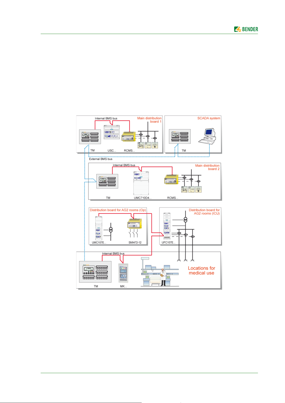
The TM800 alarm indicator and operator panel is an integral component of the MEDICS® system.
MEDICS
Example of a section of a hospital with the MEDICS
®
is an intelligent system that guarantees safe power supply in medical locations.
®
system
Legend to the illustration above
MK… Alarm indicator and test combination
RCMS… Residual current monitoring system for TN-S systems
SMI472 Signal converter for third-party technical equipment (e.g. med. gases, BSV (battery-
supported systems)
TM… Alarm indicator and operator panel
UFC107E… Changeover and monitoring module for IT systems with EDS insulation fault location system
UMC107E… Changeover and monitoring module for IT systems
UMC710D… Changeover module for main distribution boards
USC710D… Control module for changeover modules (preferably in main distribution boards)
SCADA system (Supervisory Control and Data Acquisition)
TM800_D00165_00_M_XXEN/06.2015
11
Page 12

System description
MEDICS® includes:
Single and three-phase monitoring modules. MEDICS
®
system modules are, for example:
UMC…, USC…, UFC… and/or EDS… insulation fault location systems
Display and operating units such as TM… alarm indicator and operator panels or MK… alarm
indicator and test combinations
Communication between these components via the BMS bus (two-wire connection).
The connection of third-party technical systems by means of protocol converters (gateways) or
via digital inputs and relay outputs.
The real strength of MEDICS
®
is to be foun d i n commun ic ation between all involved components and
the resulting information provided to the user. The functionality of the equipment is continuously
monitored. Operating states, irregularities, faults and equipment failures are displayed. This means
high operational reliability of the installation for the user.
3.2 TM800 features
On its backlit LC display, the TM800 displays messages from all BMS-bus devices and digital inputs
assigned via alarm addresses. As well as being used as a standalone indicator, the TM800 also supports parallel indication in different rooms. In the event of an alarm message, the yellow LED "WARNING" or the red LED "ALARM" lights up and the message appears on the LC display in plain text
format. At the same time there is an audible signal (can be acknowledged/muted). If a second message is received whilst the first is still pending, the audible signal will sound again and the messages
will appear alternately on the LC display. The address of the device triggering the alarm can also be
called up. The audible signal sounds again once a configurable period of time has elapsed (repetition
can be deactivated). Illuminated pushbuttons can be programmed to signal alarms and operating
states or for programming operating information. Operator actions or messages can be output via
digital outputs.
Internal device parameters (alarm addresses, test addresses…) and the parameter setting of EDSand RCMS systems can be accessed via the menu system. TM800 can be also be used as a master device in installations with a number of IT and EDS systems.
The test button can be used to check the function of the associated devices such as insulation monitoring devices, LIM (Line Isolation Monitors) or GFCI (Ground Fault Circuit interrupters). The message
is output only on the TM800 on which the test button "TEST" was pressed. The test and its individual
evaluations are carried out sequentially. Finally, a message appears indicating either a successful test
or a fault.
TM800 features:
Display, control and operation of Bender monitoring systems and third-party systems
Backlit clear LC text display (4 x 20 characters, 8 mm)
Additional text with specific information for technical and medical personnel can be displayed
LEDs in traffic light colours: 3 LEDs for optical differentiation of messages
Predetermined standard texts in 21 languages for Bender MEDICS® systems
1000 freely programmable message texts (with TMK-SET PC software)
Audible alarm (can be acknowledged or muted)
Easy parameterisation:
– with a personal computer (USB interface, BMS bus): TM800, MK800, EDS46x, EDS47x,
EDS49x, RCMS460, RCMS470, RCMS490
– via menu: TM800 basic parameters
12
TM800_D00165_00_M_XXEN/06.2015
Page 13
System description
Betrieb Warnung Störung
History memory with real-time clock to store 1000 warning and alarm messages
Variable operator and display modules with a freely programmable function
Easy integration with third-party systems, because operating theatre table controls, medical
gases, intercom systems are behind a closed foil surface
Control of third-party systems by flexible I/O modules with galvanic separation
Alarm LED at each input/output for fast diagnosis
Functions can be easily extended by adding I/O modules
Clearly defined structure thanks to an external and internal bus
Non-reflecting, multi-coloured foil surface
Optionally available with an antibacterial foil surface
3.3 Functionality of the TM800
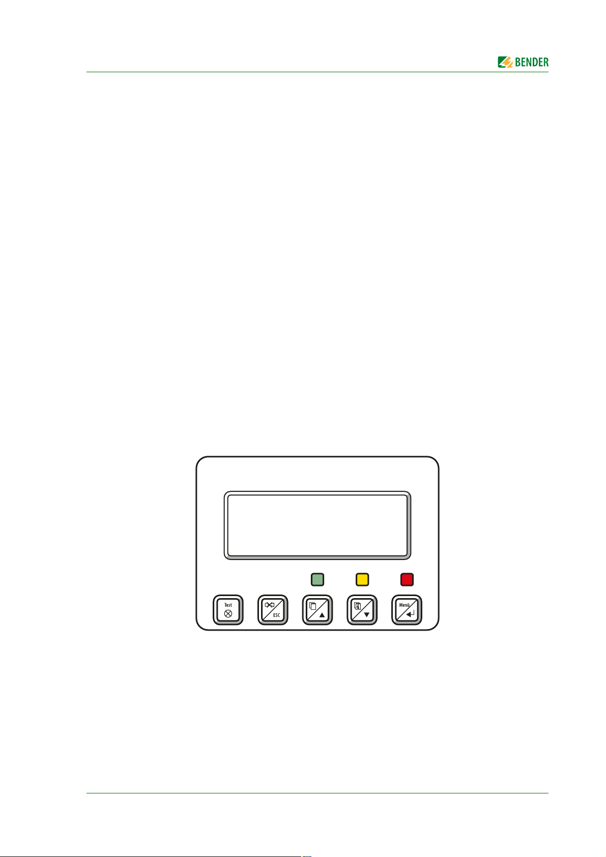
3.3.1 LC display
The backlit features four lines of 20 characters. It assists medical and technical personnel during the
decision-making process with information that is always clear and unambiguous. Every alarm message comprises three lines which appear spontaneously and three additional lines which can be displayed at the touch of a button. The fourth line contains status information (the number of
messages, test procedures, menu information).
Below the text display, three LEDs are arranged. They indicate: normal operation (green), warning
(yellow) or alarm messages (red).
Five buttons are available to acknowledge or to mute alarm and warning messages, for testing the
assigned devices and for the menu system.
TM800_D00165_00_M_XXEN/06.2015
13
Page 14

System description
3.3.2 Programmable messages
Standard message texts can be activated by enabling alarm addresses. These texts are available in
21 national languages. Alarm addresses can be enabled via the device menu system (without personal computer). Individual message texts, each comprising 6 lines à 20 characters can be programmed with the TMK-SET software. Up to three outputs can be assigned to each alarm.
An LED (yellow or red) and an audible signal can be assigned to each message. For this purpose, the
PC is connected to the USB interface or BMS bus (RS-485). In addition to the buzzer, a relay can be
activated that enables, for example, an alarm horn sound in a loud environment.
3.3.3 History memory
Warnings and alarms with date and time stamp are automatically written to the history memory.
1000 text messages can be stored. Each subsequent message overwrites the oldest message in the
history memory (message 1001 will overwrite message 1 etc.). The history memory can be read out
via the operating menu or the TMK-history PC software.
3.3.4 Interfaces
Alarm indicator and operator panels feature different interfaces, for communication with third-party
systems and/or MEDICS
–Internal BMS bus
–External BMS bus
–USB interface
®
components:
3.3.4.1 BMS bus
The BMS bus system (BMS=Bender Measuring Device Interface) guarantees high operational reliability:
Based on the tried and tested industrial standard RS-485
A self-contained system - not influenced by third-party systems
Redundant master function and data transmission (internal and external bus)
Mutual device monitoring
Open, thanks to defined interfaces, e.g. OPC server
Internal BMS bus
The internal BMS bus is used for communication with BMS bus devices,
– e.g. modules like UMC…, UMA…, UFA…, UFC…, LFC…, ATICS®
– or devices like RCMS…, EDS…, SMI…, SMO…, MK800…, TM800
Up to 30 devices can be connected to each internal bus line (in combination with the DI-1PSM repeater up to 150). One address is assigned to each bus device. Address 1 is assigned to the TM800
alarm indicator and operator panel which represents the master on the internal bus.
If the external BMS bus is switched off, addresses 2…150 (slave) can be selected on the internal bus.
14
TM800_D00165_00_M_XXEN/06.2015
Page 15

System description
External BMS bus
The external BMS bus enables communication with other TM800 alarm indicator and operator panels, SMI472-12 or BMS-OPC servers. The master function is cyclically passed to the subsequent master on the external bus. The TM800, with address 1, however, takes over some special tasks:
– As a "master clock", it synchronises the time of all devices on the internal BMS bus
– It ensures that the required supply voltage is available on the external BMS bus.
Messages can be displayed on any TM800 alarm indicator and operator panel via the external BMS
bus. The PC software TMK-SET is used to assign the messages accordingly.
A personal computer is recommended to be connected via the external BMS bus to the TM800 alarm
indicator and operator panel. Any information of the TM800 panels connected to the external BMS
bus can be displayed and set at a central point. If the personal computer does not feature an RS-485
interface, an RS-232/RS-485 converter DI-2 or a USB/RS-485 converter DI-2USB will be required.
3.3.4.2 USB interface
A personal computer can also be connected to the TM800 via the USB interface using a standard-USB
device cable (type A/type B). To access the USB interface plug, open the front plate.
Only the connected TM800 can be read out and set via the USB interface.
3.3.5 Programming and reading the TM800
3.3.5.1 Connection of the personal computer
Connect the TM800 to a personal computer:
directly via the USB interface or
via an RS-232/RS-485 converter DI-2 or a USB/RS-485 converter DI-2USB to the internal or exter-
nal BMS bus.
3.3.5.2 Optional software
You can use the PC software TMK-SET to read, display and change the TM800 settings.
You can use the PC software TMK-History to read the history memory of the TM800 (download
from http://www.bender-de.com).
BMS-OPC server
3.3.6 Firmware versions
The TM800 is controlled by an internal software (firmware).
All devices sharing one external BMS bus must be equipped with compatible
software versions. The following software versions are required:
TM V 4.0 or higher
SMI472 V 2.03 or higher
TM800_D00165_00_M_XXEN/06.2015
All devices must be set to the same baud rate.
15
Page 16

System description
3.4 Mechanical design
3.4.1 Module overview
The TM800 alarm indicator and operator panels are based on a modular design. The appropriate
combination of modules will be made by Bender so that the user is not unnecessarily burdened with
planning details. This chapter provides a summary of the applicable modules:
BM800 Module for TM800 alarm indicator and operator panel
BM400 module like BM800, but without an LC display and control buttons
BI… operating and display modules each with five illuminated pushbuttons
BMI… I/O modules (digital inputs, relay outputs, open collector outputs)
Individual components (remote operating table control, intercom systems…)
3.4.2 BM800 and BM400 modules
3.4.2.1 BM800
Module for a TM800 alarm indicator and operator panel with LC display. BM800 features:
– LC display (without a front foil, because this is included already in the front plate of TM800)
– one operating LED, warning and alarm LED each as common alarm LEDs
– 5 control buttons
– Interfaces 2 x RS-485, 1 x USB, 2 x I²C
–Buzzer
3.4.2.2 BM400
BM400 is a module similar to BM800, but without LC display and control buttons. These operating
and display modules together with digital I/O modules can be configured to form indicator and operator panels.
3.4.3 Operating and display modules
The operating and display modules consist of 5 elements. Depending on the panel type, different
numbers of modules are available (also see "Internal components and modules" on page 77ff).
Type Characteristics
BI800S Operating and display elements to expand the BM800/BM400 modules. 16 BI800S
modules can be controlled via I²C bus. One individual function (switch, button, LED etc.)
can be assigned to each element.
BI71S Operating and display elements without an I²C bus:
5 illuminated pushbuttons, 5 potential free changeover contacts, max. AC 250 V/8 A.
BI72S Operating and display elements without an I²C bus:
5 illuminated pushbuttons, 5 potential free changeover contacts, max. AC 24 V/0.9 A
16
TM800_D00165_00_M_XXEN/06.2015
Page 17
System description
3.4.4 Inputs and outputs
Digital inputs and outputs as well as relay outputs are available for the control and indication of different technical equipment. The I/O modules are controlled via I²C bus.
The digital inputs are designed for a voltage of AC/DC 0…30 V (HIGH=10…30 V; LOW=0…2 V). In
practice, these digital inputs are controlled via an internal or external voltage and potential-free contacts (N/C or N/O operation, selectable). The voltage required for these inputs can be supplied by the
built-in power supply unit. The behaviour of the alarm contact at the digital input (N/O contact or N/
C contact) can be assigned via this PC software. That means that the hardware of the alarm indicator
and operator panel does not need to be changed in case of subsequent changes of the contact behaviour.
Digital inputs or outputs (potential free relay contacts or open collector outputs) are controlled by
warning or alarm messages, via operating and display modules or the digital inputs. A message, a
digital input or an illuminated pushbutton can be assigned to a relay output via the PC software
TMK-SET.
The I/O modules are snapped on a DIN rail in the flush-mounting box separately from the display and
the pushbutton panels. So the system can easily be expanded. Each input and output provides an
alarm LED so that the status is visible at a glance for the technical staff.
3.4.4.1 Digital output 1
When an I/O module BMI8/8, BMI8/4 or BMI0/4 is built in, the first output can be programmed individually. It can be used for system functions (see "Settings menu 11: Relays" on page 65). The output
switches when:
– an internal TM800 device error is recognised
– the test button is pressed (relay will be activated for approx. 1.5 s)
– a device failure is recognised on the BMS bus,
– any warning or alarm message occurs (common alarm)
– the buzzer sounds (relay is activated when buzzer sounding)
The output can also be programmed via TMK-SET like all other outputs.
TM800 alarm indicator and operator panels offer safe separation according to
IEC 60664 between the relay contacts and the electronics, interface outputs, digital inputs and among each other.
3.4.4.2 I/O modules
Type Characteristics
BMI8/8 8 digital inputs, 8 open collector outputs
The open collector outputs are capable of driving a load of up to 15 W at an operating
voltage of 24 V. They feature flyback diodes for the connection of relays.
TM800_D00165_00_M_XXEN/06.2015
17
Page 18
System description
Type Characteristics
BMI8/4 8 digital inputs, 4 relay outputs
The digital outputs correspond to those of the BI8/8 module. The potential-free output
relays feature one changeover contact eachAC 250 V, 5 A (AC1).
BMI0/4 Expansion for BMI8/4 by 4 relay outputs. The module BMI0/4 can only be used in com-
bination with the BMI8/4 module. The potential-free output relays feature one changeover contact each AC 250 V, 5 A (AC1).
3.4.5 Individual internal components
In addition to the operating functions activated via operating and display modules, often complete
operating units from a third-party manufacturer are integrated into the alarm indicator and operator
panel. Typical examples are operating table controls or intercom systems. These modules are integrated in the alarm indicator and operator panels by Bender so that an aesthetically attractive functional solution is available, documented by the official release of the manufacturer. The required
connections are made in accordance with the specifications of the respective manufacturer.
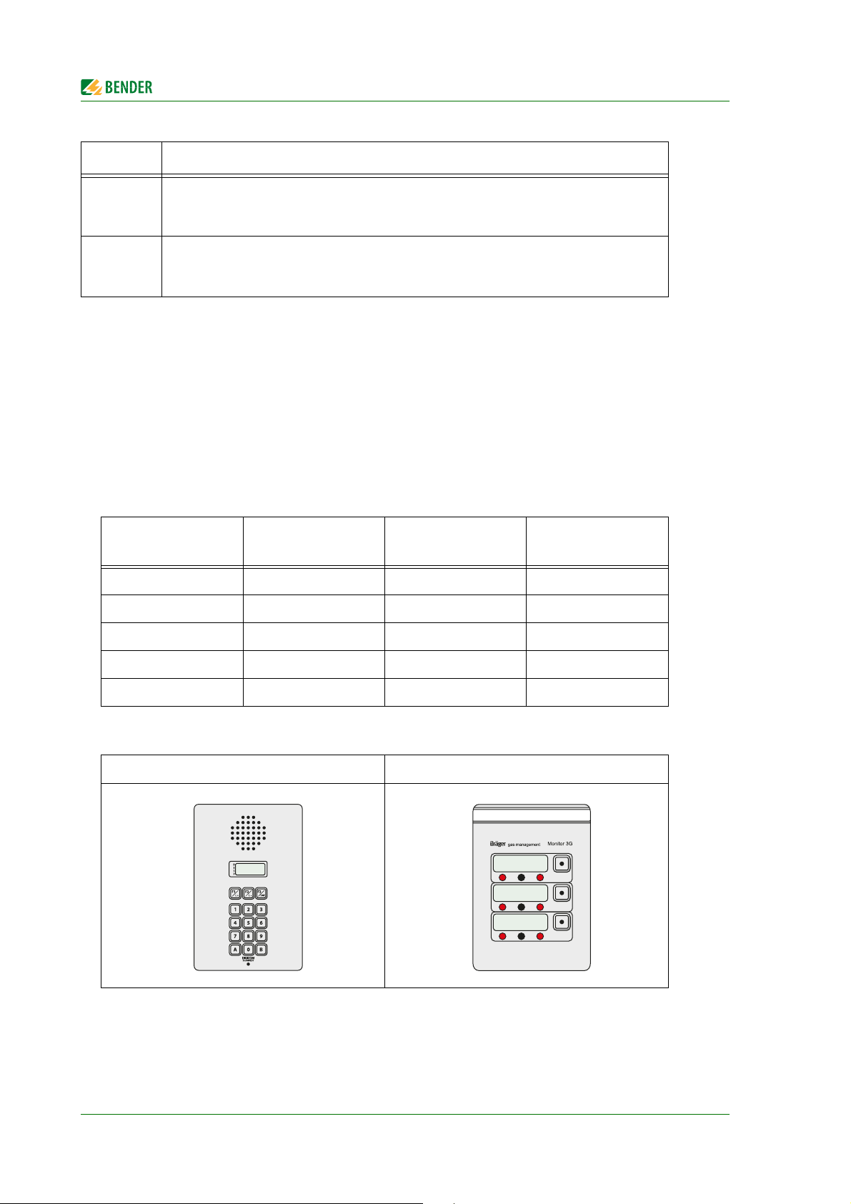
Typical examples of third-party systems used in medical locations
Med. gases Intercom systems
Dräger Digicom-Scanvest ALM Maquet
Gehrke Berchtold Trumpf
Schneider Dräger
Stentofon Haraeus
Telecom Behnke
Operating theatre
light
Operating theatre
table
Intercom system – Digicom Dräger Monitor 3G
18
TM800_D00165_00_M_XXEN/06.2015
Page 19

4. Installation and connection
4.1 Installation
4.1.1 Overview of enclosure variants
The design of the alarm indicator and operator panels is based on the individual customer requirements in terms of interior design and the architect's and constructor's needs. In addition to the basic
versions also room-high stainless-steel alarm indicator and operator panels or other versions are
available.
The foil surface is completely closed, i.e. there are no screws needed for fixing the front plate. The
panel is easy to clean so that a high standard of hygiene is guaranteed. For additional protection, the
front panel surface can also be delivered with antibacterial surface.
Flush-mounting type enclosure with bezel frame (UPB)
A gap of up to 12 mm between the flush-mounted enclosure and the wall can be concealed by a bezel frame made of anodised aluminium. This version is recommended to be used for wallpapered
walls or walls with non-standard tiles, for example.
Flush-mounting type enclosure with mounting frame (UPE)
The mounting frame permits accurate and close wall mounting. The mounting frame is made of anodised aluminium. The mounting frame version is preferably used where the enclosure is required
to fit exactly the dimension of the tiles.
TM800_D00165_00_M_XXEN/06.2015
19
Page 20
Installation and connection
WARNING
WARNING
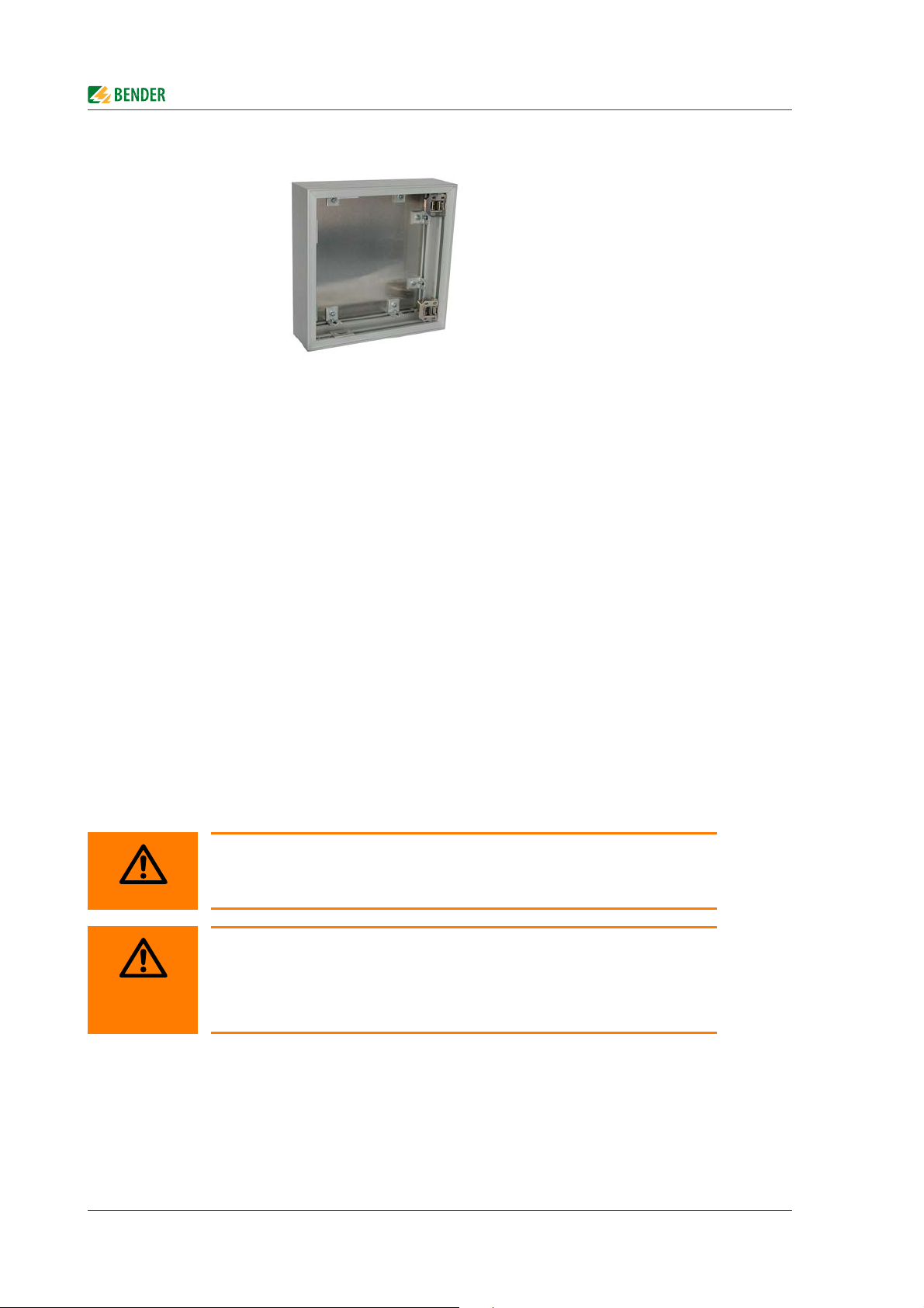
Surface-mounting enclosure (AP)
The anodised surface-mounting enclosure is suitable for both pure surface-mounting and for partially recessed mounting. The enclosures can be supplied with a depth of 90, 150 and 210 mm.
The support frame inside the flush-mounted or surface-mounted case is fitted with a long-term elastic seal in order to avoid the ingress of cleaning agents into the panel. Depending on the size, the
front plate is connected to the flush mounting or surface mounting enclosure by two or more stable
hinges. This guarantees easy installation of the alarm indicator and operator panel.
All necessary modules and display elements are permanently fixed to the front plate using threaded
bolts or mounting frames. The front plate is connected with the mounting plate via a flexible spiral
hose that is fixed on both sides with cable clips. The technical equipment and systems are connected
to a terminal board that is fixed on a mounting plate. The power supply unit for the alarm indicator
and operator panel is also located on this mounting plate. The mounting plate can easily be dismantled. That allows the flush-mounting or surface-mounting enclosure to be installed prior to the final
assembly stage. Cable connections between the front plate and the terminal board also do not need
to be disconnected.
With the exception of the mounting plate no other components are fixed to the baseplate of the
flush-mounting/surface-mounting enclosure, allowing sufficient room for installation.
4.1.2 Unpacking
Unpack all the parts supplied with the system. Do not use sharp-edged tools that may damage the
content of the packaging.
Compare your order with our delivery note to check that you have received all products in full. The
article numbers printed on the nameplates simplifies the identification of the devices.
Check all parts supplied for any evidence of damage in transit. Devices damaged
in transit must not be used. If a device is damaged, please contact Bender. Details
of who to contact are indicated on the delivery document.
Before using devices that have been stored at low temperates: Leave the devices
to stand for 3 to 4 hours at room temperature before connecting the power supply. A change in temperature from cold to warm will result in condensation on all
device components. Putting damp devices into operation risks damaging electrical components and there is a danger of electric shock on contact.
20
TM800_D00165_00_M_XXEN/06.2015
Page 21

Installation and connection
Drawing no.: 9800267
4.1.3 Installing the flush-mounting type enclosure with bezel frame (UPB)
Note: Do not remove the plaster cover and the fixing brackets during the installation to protect the
wall-mounting enclosure!
1. Before inserting the cables remove the knockouts. Guide the power supply cables into the
enclosure.
2. Install the flush-mounting enclosure in a way that the enclosure (and thus the plaster cover)
are approximately 2 mm below the finished surface of the wall.
3. After installing the enclosure securely, remove the plaster cover and the fixing brackets. Then
install the bezel frame into the flush mounting enclosure.
TM800_D00165_00_M_XXEN/06.2015
21
Page 22

Installation and connection
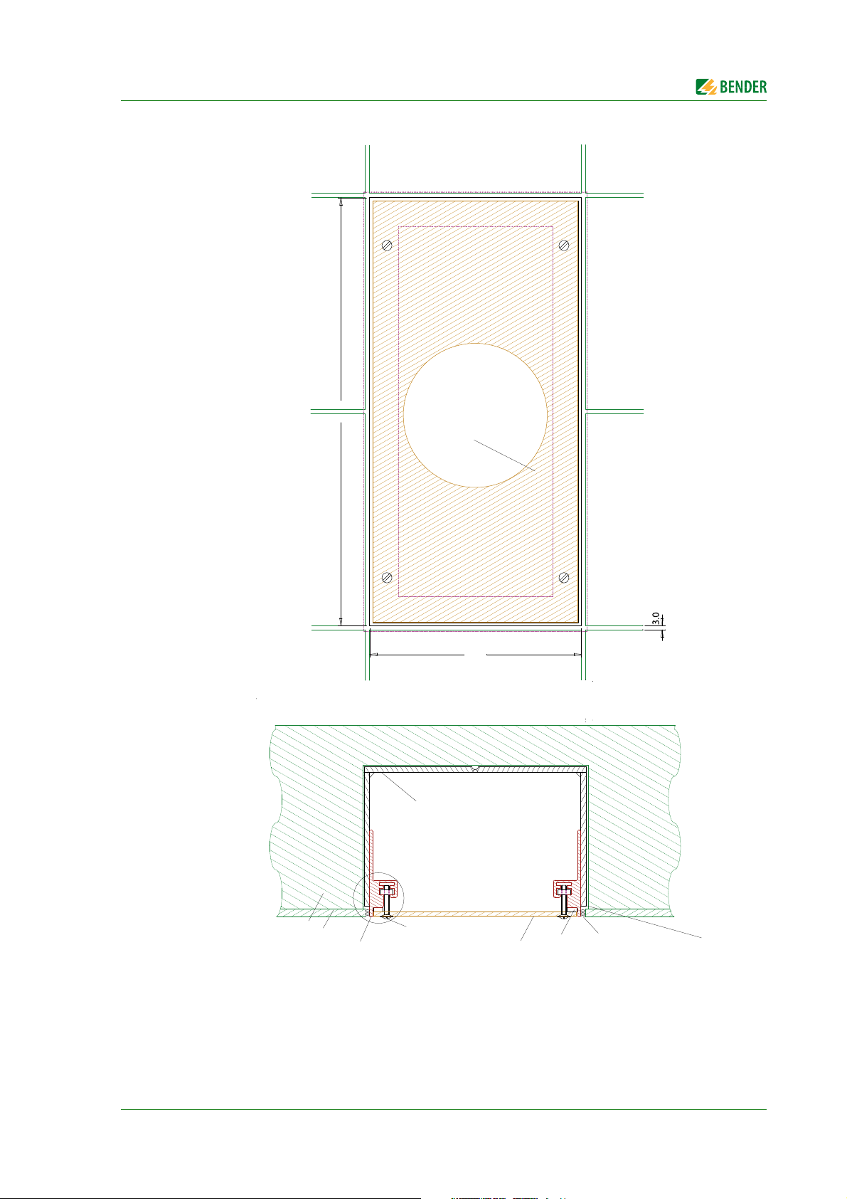
4.1.4 Installing the flush-mounting enclosure with mounting frame (UPE)
The front plates are fitted into the wall-mounting enclosure and identified by a number identical to
the number of the enclosure. The front plate number must be identical to the enclosure number!
Note: Do not remove the plaster cover during the installation to protect the wall-mounting enclosure!
1. Before inserting the cables remove the knockouts. Lead the power supply cables into the
enclosure.
2. Install the mounting frame and the wall-mounting enclosure (UPE) deeper than the finished
wall surface (i.e. tile thickness plus adhesive thickness). Note: The wall-mounting enclosure is
partially covered by the wall surface (e.g. tile)
3. Once the enclosure is firmly installed and the joints are filled, the plaster cover can be
removed.
Size of the panel and flush-mounting enclosure
Typical tile grid
150 mm tile grid= 147 mm tile + 3 mm joint
153 mm tile grid= 150 mm tile + 3 mm joint
Calculation of the panel size
Panel dimension = number of tiles x tile grid - one joint width
Example:
Panel dimension = 2 x 150 mm - 3 mm
Panel dimension = 297 mm
Calculation of the flush-mounting enclosure size
Flush-mounting enclosure dimension= Number of tiles x tile grid - one joint width + 10 mm
Example:
Flush-mounting enclosure dimension= 2 x 150 mm - 3 mm + 10 mm
Flush-mounting enclosure dimension= 307 mm
22
TM800_D00165_00_M_XXEN/06.2015
Page 23
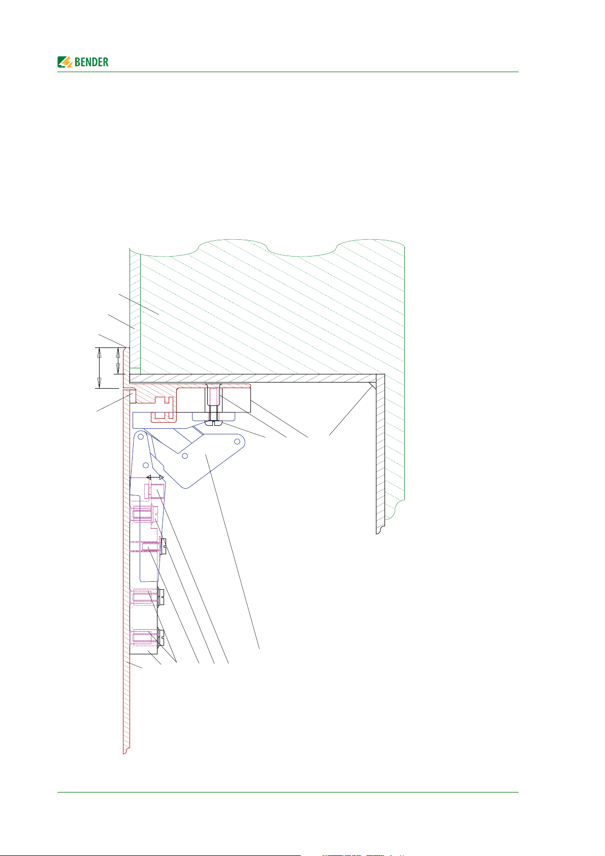
Installation and connection
wall surface, tiles
inside mounted plaster frame, anodized alum-profile, 2mm
brick wall
slotted oval head screw, M4x20mm
with washer and nut
mounting lid
seal
backbox, 4mm
depth as specified
p
l
a
s
t
e
r
3
m
m
297.0
mounting lid
1
4
7
.
0
Drawing no9800268
TM800_D00165_00_M_XXEN/06.2015
23
Page 24
Installation and connection
Drawing no.: 9800269
4.1.5 Mounting the front plate
The front plates are fitted into the flush-mounting enclosure and are marked with a number that is
identical to the number of the enclosure. The front plate number must be identical to the enclosure
number!
Install the hinges of the front plate as described in the drawing below:
4.1.5.1 Flush-mounting type enclosure with bezel frame (UPB)
brick wall
wall surface
adjustable height max. 20mm
bezel/cover frame + alum.-profile, 3mm
20.0
seal
13.0
rivet nut M4
backbox, 4mm
depth as specified
spacer WxHxD 52x35x12
slotted pan head machine screw,M4x16mm
24
frontplate, 3mm, Alum.
hinge
hinge
hinge fixing
+ M4x12 screw
Alum. mountingplate
welded stud M4x5x6x8
horizontal adjustment
hinge fixing
screw M4x8
vertical adjustment
Fixing instructions see on dwg# 9800373EA+B
Mounting instructions see on dwg# 9800267E
Optional: spring catch, see dwg# 9800266E
TM800_D00165_00_M_XXEN/06.2015
Page 25
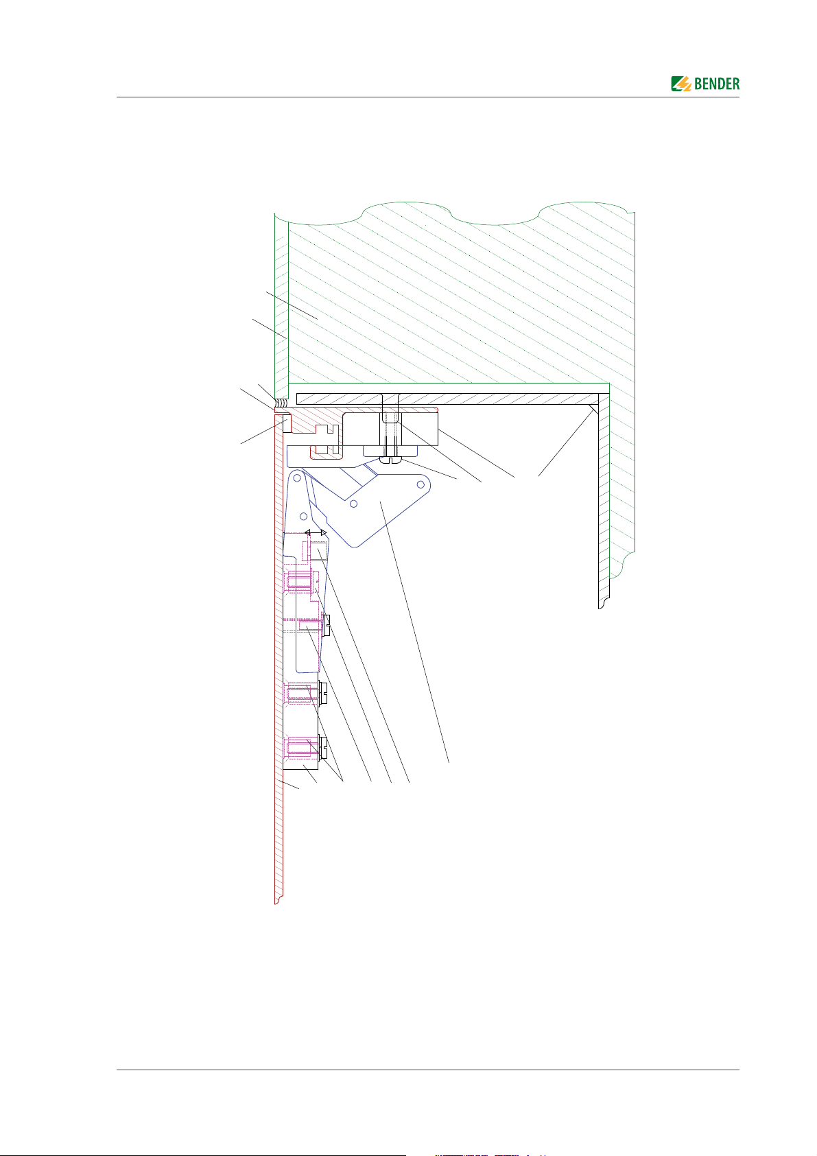
Installation and connection
in side mouted plaster frame, anodized alum-profile, 2mm
adjustable in depth by 15mm
wall surface, tiles
brick wall
seal
plaster, 3mm
slotted pan head machine screw,M4x16mm
frontplate, 3mm, Alum.
Alum. mountingplate
welded stud M4x5x6x8
+ M4x12 screw
hinge fixing
horizontal adjustment
screw M4x8
hinge fixing
vertical adjustment
Hinge
spacer WxHxD 42x35x6
depth as specified
Fixing instruction see on dwg# 9800374EA+B
Mounting instructions see on dwg# 9800268E
Optional: spring catch, see dwg# 9800266E
rivet nut M4
backbox, 4mm
Drawing no.: 9800272
4.1.5.2 Flush-mounting type enclosure with mounting frame (UPE)
TM800_D00165_00_M_XXEN/06.2015
25
Page 26
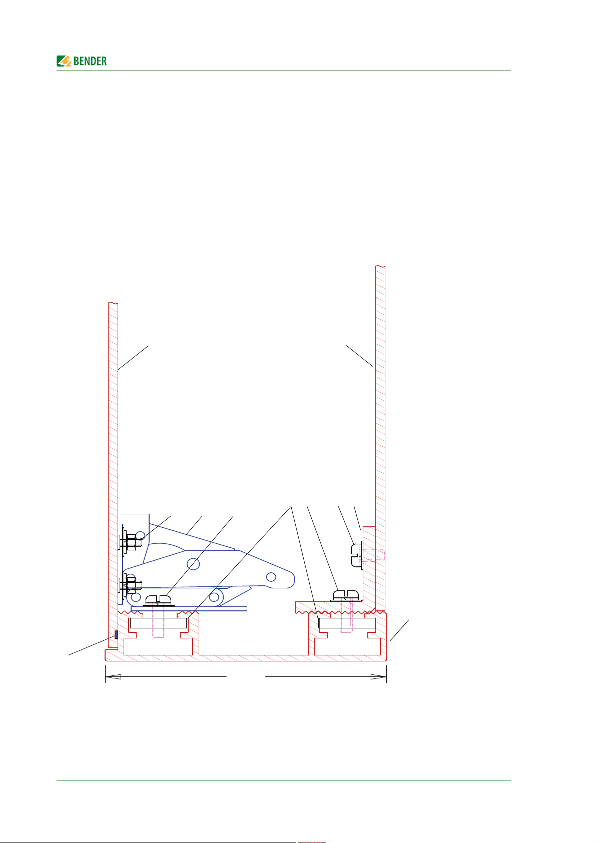
Installation and connection
Threaded bolt
T
Threaded bolt M3x12 mm
Hinge
Screw M4x12 mm
Slide nut M4
Screw M4x12 mm
Screw M4x10 mm
Fastening angle for base plate
Base plate, aluminium, 3 mm
Front plate, aluminium, 3 mm
Profile enclosure made of anodized aluminium
T = depth: 90, 150 mm (210 mm on request)
Drawing no.: 9800274
4.1.6 Installation of the surface-mounting enclosure (AP)
1. Open the front plate as described in chapter "4.1.7 Opening the front plate".
2. Drill holes into the enclosure for wall mounting and cable entries. The holes are not pre-drilled
so that local conditions can be considered. However, you must ensure that the cables are positioned in such a way that there is enough space left for the circuit-boards when the frontplate
is closed.
3. Fix the enclosure to the wall using stainless screws.
4. Lead the power supply cables into the enclosure.
26
TM800_D00165_00_M_XXEN/06.2015
Page 27
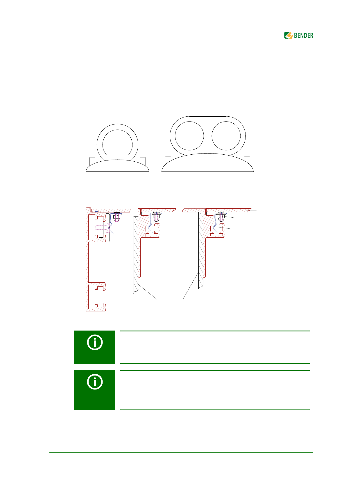
Installation and connection
Suction cup d=80 mm
or
Suction cup d=55 mm
Art. No. 102851
Art. No. 102850
steel C75 - H&H
spring catch, 12.5mm
welded stud,
front plate, 3 mm, alum.
M3x6 mm
For following wallboxes:
surface-mounting frame
(AP)
(UPE)
mounting frame
(UPB)
bezel frame
backbox, 4 mm
Drawing no.: 9800266
4.1.7 Opening the front plate
It should only be possible to open the enclosure with a keys or a tool (as, for example a suction cup,
screw driver). This is required by the following standards:
VDE 0660, part 500, chapter 7.4.2.2.3. a)
EN 60439-1, chapter 7.4.2.2.3. a)
IEC 60439-1, chapter 7.4.2.2.3. a)
TM800_D00165_00_M_XXEN/06.2015
Factory-delivered, TM800 panels come with a textile lug that protrudes between
the frame and the front plate. This allows the front plate to be opened for commissioning without the use of a tool. Make sure this textile lug no longer protrudes from the enclosure after commissioning.
Components protruding from the front plate (such as socket-outlets, remote operating theatre table control) which could enable the user to hold on to them
and to open the alarm indicator and operator panel are secured by means of a
screw located in the middle of the side opposite the hinges:
Raised countersunk head screw, M4x10 with rosette.
27
Page 28
4.2 Connection
DANGER
DANGER
CAUTION
CAUTION
CAUTION
Risk of electric shock!
Before fitting the enclosure and working on the device connections, make sure
that the power supply has been disconnected.
Failure to comply with this requirement will expose personnel to the risk of an
electric shock. Furthermore, the electrical installation may be damaged and the
device destroyed beyond repair.
Connect the TM800 alarm indicator and operator panel exclusively according to
the wiring diagram supplied with the device. Do not make any changes to the
internal wiring. Wiring not conforming to the accompanying diagram or unauthorised modifications may result in the TM800 malfunctioning or completely
failing to operate.
If inductive loads and the TM800 share a common voltage source, it is absolutely
necessary to use flyback diodes directly at the inductive load. Always use a separate power supply for the operation of impulse relays in order to avoid interferences.
Installation and connection
Make sure that the power supply of the TM800 is isolated against PE. If this is
not taken into account and a personal computer is connected to the USB interface the TM800 or the personal computer may be damaged.
The device contains components that can be damaged by electrostatic dis-
charges (ESD). If work requires the opening of the device, the safety precautions
concerning the dissipation of electrostatic electricity have to be observed.
4.2.1 Connection details
The following connections are available on modules installed in the lower part of the enclosure:
Connect the supply voltage to the terminals 0 and 230 V of the TM800's power supply unit. The
standard supply voltage is AC 230 V.
The terminals for the digital inputs, the open collector outputs and the relay outputs are availa-
ble on the associated I/O modules BMI8/8, BMI8/4, BMI0/4. Use cables with a cable cross section
of at least 0.75 mm
length per connection is 500 m.
A terminal board allows the connection to the internal and external BMS bus (internal bus = ter-
minals iA/iB, external bus = terminals eA/eB).
Connect the BMS bus according to the instructions in chapter "4.2.3 BMS-bus connection" and
in the "BMS bus" leaflet. Use a shielded cable of at least mm or 0.8 mm cross section for the
interface line (e.g. J-Y(St)Y n x 2x0.8). The terminals iS resp. eS are used to connect the shield of
the respective BMS bus. The shield must be connected to earth at one end. The shield may in no
circumstances be earthed at several points.
2
for the connection of digital inputs and relay outputs. The maximum cable
28
TM800_D00165_00_M_XXEN/06.2015
Page 29

Installation and connection
eA eB eS iA iB iS
eA
eBeSiA
iB
iS
BI800
BI800
BI800
BI800
BM800
A
B
1
D
6
2
345
978
C
4.2.2 Modules and connections of the TM800 (connection example)
TM800_D00165_00_M_XXEN/06.2015
29
Page 30

Legend to wiring diagram
A Back of the front plate
B Mounting plate, installed in the bottom part of the enclosure.
Installation and connection
C
2
C bus, is used for communication between the modules BM800 (resp. BM400) and the
I
operating and display modules BI800S. The terminals of the two I
2
C buses must not be
interchanged!
D
2
C bus, is used for communication between the modules BM800 (or BM400) and the I/O
I
modules BMI8/8, BMI8/4 and BMI0/4. The terminals of the two I
2
C buses must not be inter-
changed!
1 Terminal board for connection to the internal and external BMS bus
internal bus = terminals iA, iB, iS, external bus = terminals eA, eB, eS)
(
2 Digital inputs of the I/O module BMI8/4, or BMI8/8
3 Open collector outputs of the I/O module BMI8/8
4 Relay outputs of the I/O module BMI8/4
5 Relay outputs of the I/O module BMI0/4
6 Connection of the supply voltage U
to the terminals 0 and 230 V of the power supply unit.
S
The standard supply voltage is AC 230 V.
7 Switch S1 to terminate the external BMS bus.
8 Switch S2 to terminate the internal BMS bus.
9 USB connection for programming purposes. Cable: Type A plug on type B plug.
TM800 modules
BM800 Module
BI800S Operating and displaying module to expand each BM800/BM400 module by five pushbut-
tons
BMI8/8 8 digital inputs, 8 open collector outputs.
The open collector outputs are capable of driving a load of up to 15 W, at an operating voltage of 24 V. They feature flyback diodes for the connection of relays.
BMI8/4 8 digital inputs, 4 relay outputs
The digital outputs correspond to those of the BMI8/8 module. The potential-free output
relays feature one changeover contact of AC 250 V, 5 A (AC1) each.
BMI0/4 Expansion for BMI8/4 by 4 additional relay outputs. The
BMI0/4 module can only be used in conjunction with BMI8/4. The potential-free output
relays feature one changeover contact of AC 250 V, 5 A (AC1) each.
Mains
Power supply unit of the TM800 alarm indicator and operator panel.
Part
30
TM800_D00165_00_M_XXEN/06.2015
Page 31

Installation and connection
4.2.3 BMS-bus connection
Communication between the TM800 alarm indicator and operator panel and other system components takes place via two serial interfaces (internal and external BMS bus). These interfaces cables are
of two-wire design. See "BMS bus" instruction leaflet for more details about the BMS bus.
The number of bus devices is limited to 30. Install a DI-1PSM repeater if you want to use more devices
on the BMS bus. A DI-1PSM also is required when the BMS bus segment of 1200 m is exceeded.
4.2.3.1 Terminating resistor
The BMS bus must be terminated at both ends with terminating resistors of 120 Ω (0.4 W). One terminating resistor is installed in each TM800 for the internal and external bus.
If several TM800 alarm indicator and operator panels are connected via the BMS bus, the terminating
resistors of the TM800 alarm indicator and operator panels which are not installed at the end of the
bus have to be switched off. The same applies to all other devices and modules that are not installed
at the end of the bus.
Missing or incorrectly installed terminating resistors (e.g. in the middle of the
bus) will cause bus instability.
Use the DIP switches S1 and S2 to set the terminating resistor for the internal and external BMS bus:
S1 = external BMS bus; S2 = internal BMS bus. Factory setting: S1 and S2: off. The DIP switches are
located on the BM800 module adjacent to the interface terminals. Use the DIP switch to select on or
off position.
BMS-bus addresses
Be sure that the addresses of all devices connected to the bus are correctly assigned. Never assign
one address twice. Assign the addresses consecutively without any gaps. Bear in mind that each bus
requires one master. A device becomes a master by assigning address 1 to it. Address assignment
can be carried out via the menu of the TM800 alarm indicator and operator panel (see "Settings
menu 10: Interface" on page 65) or via the basic settings in the TMK-SET software.
Internal BMS bus
Select an address between 1 and 150 for the internal bus of the alarm indicator and operator panel
(factory setting: 1). The addresses 100…103 are reserved for special tasks (e.g. programming). This
setting can only be changed when the external bus has been switched off before. On the internal
BMS bus the baud rate is set to a fixed value of 9600 bits/s.
External BMS bus
Select an address between 1 and 99 for the BMS bus of the TM800 alarm indicator and operator panel.
The external bus is primarily used for the connection of several TM800 alarm indicator and operator
panels. But also MK800 alarm indicator and test combinations and SMI472-12 signal converters can
be connected. Up to 99 devices can be connected.
The following applies to the external bus:
When the TM800 alarm indicator and operator panel is the only control device in the system,
address 1 (Master) is assigned to it.
TM800_D00165_00_M_XXEN/06.2015
31
Page 32

Installation and connection
CAUTION
On the external bus, the Master function can be cyclically passed from one address to the next
higher one.
The addresses are consecutively assigned to additional TM800 alarm indicator
and operator panels (2, 3 etc.). Only when there are no gaps between the addresses, reliable function can be ensured.
All devices on the external bus must be equipped with compatible software versions (see chapter "3.3.6 ").
All devices must be set to the same baud rate.
4.3 Examples for connection and address assignment
Example Devices on the internal bus
Changeover and monitoring module UMC107E-… with alarm indicator and operator panel TM800 and
3 alarm indicator and test combinations MK2430. All components are connected to the TM800 via the internal RS-485 interface.
32
TM800_D00165_00_M_XXEN/06.2015
Page 33

Installation and connection
Example 2: Parallel operator panel
Changeover and monitoring module UMC107E-… with an alarm indicator and operator panel TM800 in
an operating theatre, a "higher-level" alarm indicator and operator panel TM800 in the technical control
room and a personal computer to evaluate the history memory of the alarm indicator and operator panels. If the personal computer does not have an RS-485 interface, an RS-232/RS-485 converter DI-2 or a
USB/RS-485 converter DI-2USB will be required.
TM800_D00165_00_M_XXEN/06.2015
33
Page 34

Example 3: Central devices on the BMS bus
Installation and connection
A three or four-pole changeover module UMC710D- with two changeover and monitoring modules
UMC107E downstream and messages from the UPS (battery-supported safety power supply) system.
Each UMC107E is connected to "its" alarm indicator and operator panel TM800 via the internal BMS bus.
The TM800 panels are connected with each other and also to a "higher-level" TM800 in the technical
room, to the SMI472-12 converter module and to a personal computer for the evaluation of the history
memory via the external BMS bus. If the personal computer does not have an RS-485 interface, an RS-232/
RS-485 converter DI-2 or a USB/RS-485 converter DI-2USB will be required.
34
TM800_D00165_00_M_XXEN/06.2015
Page 35

Installation and connection
4.3.1 Address settings and their meaning
Display
Meaning
External address Internal address
0 (ext. bus on) 0 -- -- --
0 (ext. bus on) 1 TM/MK itself -- dig. IN*
0 (ext. bus off ) M = own addr. TM/MK itself -- dig. IN*
0 (ext. bus off) M <> own addr Device M on the
int. bus of the
own device
N = own addr. 0 Device N on the
external bus
N = own addr. 1 TM/MK itself -- dig. IN*
N = own addr. M > 1 Device M on the
int. bus of the
own device
N <> own addr. 0 Device N on the
external bus
N <> own addr. 1 Device N on the
external bus
Setting
on TM/MK800
ext: 0/int: M int. bus: int M
-- dig. IN*
-- int. bus: int M
ext: N/int: 0 ext. bus: ext: N,
-- ext. bus: ext: N,
Setting
on TMK-SET
int: 0
int: 0
N <> own addr. M > 1 Device M on the
int. bus of device
N
ext: N/int: M ext. bus: ext: N,
int: M
TM800_D00165_00_M_XXEN/06.2015
35
Page 36

Installation and connection
Explanatory note to the digital inputs (*)
Alarm messages from digital inputs on TM/MK800 are always displayed on the device itself regardless of whether an individual message has been programmed or not (Exception:
channel is deactivated).
An entry into the alarm address table is not required.
If no individual message is programmed, the standard text will be displayed.
An alarm message can also be programmed to be displayed without text/LED/buzzer (silent
message).
Note: Flashing alarm messages are not allowed!
In principle, all alarm messages are stored in the history memory (Exception: channel is deactivated):
If no individual message is programmed, the standard text will be displayed resp. will be stored
in the history memory.
If the message has been programmed without a text (silent message), its source (DigIn resp.
address and channel No.) will be stored in the history memory (no individual text possible!).
Test messages are only stored in the history memory of the device that triggered the message.
Transmission via BMS bus:
All alarm messages are actively sent (i.e. as a new message) via the external or internal BMS.
Operating messages are actively sent via the external BMS bus and are not stored in the history
memory.
Note: Flashing messages must be avoided, where possible, and on no account be sent via the
int./ext. BMS bus!
The first 16 digital inputs can be configured as "flashing" and in this case are not signalled via
the external BMS. This is only permissible for messages with a flashing frequency of 0.5 Hz!
Inputs that are assigned to operating messages or switching commands are not displayed with a text
message or stored into the history memory.
36
TM800_D00165_00_M_XXEN/06.2015
Page 37

5. Commissioning and testing
Start commissioning according to the following commissioning pattern:
1. Tests before switching on
2. Tests after switching on
3. Set parameters (parameterisation)
4. Settings at the TM800
5. Settings in the TMK-SET software
6. Tests after parameter setting
Write down all settings and keep it together with the device and installation documentation.
When setting the TM800 with the configuration softwareTMK-SET, a project file
will be created. Save this file. Create a backup copy of this file and keep it in a safe
place.
TM800_D00165_00_M_XXEN/06.2015
37
Page 38

5.1 Tests before switching on
Is the power supply
connected correctly?
Does the supply voltage
match the information on
the TM800 nameplate?
Are terminating resistors
installed resp. switched
oncorrectly at the beginning
and end of the BMS bus?
no
Provide the appropriate
operating voltage
Connect the supply voltage
correctly
Is the BMS bus (int./ext.)
connected correctly?
no
Connect the supply voltage
correctly. Check polarity of
the terminals A/B!
Install/connect the
terminating resistors
correctly (at TM800 by
means of DIP switch "Term"
on/off)
yes
yes
yes
TM800 with BMI8/8 resp.
BMI8/4 only: Are the digital
inputs connected correctly
and do they have the right
potential?
Make corrections
yes
yes
no
no
no
TM800 with BMI8/4 resp.
BMI0/4 only: Are the relay
outputs connected
correctly?
Make corrections
yes
no
no
Are the other devices
connected correctly?
Make corrections
yes
Are all BMS bus device
addresses set according to
the plan?
Make corrections, first
check that the supply
voltage is switched on.
yes
Have all rules specified
in the "BMS bus" instruction
leaflet been observed?
Make corrections
yes
Is the software and
hardware of all devices in
the system up to date?
Update older devices
yes
Switch voltage supply on.
Then proceed with "tests
after switching on"
no
no
no
Commissioning and testing
Continue with chapter "Tests after switching on" on page 39.
38
TM800_D00165_00_M_XXEN/06.2015
Page 39

Commissioning and testing
Measure the supply voltage
of TM800 (terminals 0,
230 V). Voltage OK?
no
Make corrections
yes
Close the TM800's front
plate
Power supply or TM800
failure? - Remedy fault!
Does one of the three LEDs
below the display light up
and does anything appear
on the TM800's display?
no
Does TM800 indicate a
fault?
Make a note of the
message. Adapt the
signalling device to the
system or remedy the fault.
yes
yes
no
Call up menu "6. External
devices". Are addresses
and software versions of the
connected devices OK?
no
Correct the address settings
of the external devices.
yes
Optional: Use the TMK-SET
software to connect the PC
to the BMS bus of the
TM800. Call up the TMKSET function "Scan bus".
Are addresses and software
versions of the connected
devices OK?
no
Correct address settings of
the external devices.
yes
Test the system. Functions
OK?
no
Change the parameter
settings of TM800.
TM800 is ready for
operation
yes
5.2 Tests after switching on
TM800_D00165_00_M_XXEN/06.2015
Continue with chapter "Make settings (parameterisation)" on page 39.
5.3 Make settings (parameterisation)
All settings can be carried out using the TMK-SET software. Alternatively, some
settings can be carried out via the TM800 menu (see diagrams).
39
Page 40

Commissioning and testing
Set language
Set BMS bus addresses
(int./ ext.)
Set alarm addresses and
system numbers
Set test addresses and
types of Isometers
TM800 with BMI8/8 resp.
BMI8/4 ?
Use of standard assignment
for medical gases/UPS
systems?
Can the buzzer sound be
differentiated from other
device signals?
Common
acknowledgement on/off
yes
Set time/date
Use of standard texts?
Use TMK-SET for
parameterisation (refer to
5.3.2)
no
Setting "medical"
Wiring acc. to specifications!
Relay: Set function and
switching behaviour
no
Adapt buzzer settings
Set and enable password
no
Relay or pushbutton
parameterisation?
yes
yes
5.3.1 Settings at the TM800
The following settings can optionally be carried out via the function buttons at the TM800 or the
TMK-SET software. Make a note of the modified settings (setting table).
Continue with chapter "Tests after parameter setting" on page 42.
40
TM800_D00165_00_M_XXEN/06.2015
Page 41

Set language
Set password
Set buzzer
Common
acknowledgement on/off
TM800 with BMI8/8 resp.
BMI8/4?
Digital inputs: Set function
and operating mode
Relay: Set function and
operating mode
Set device address
Standard display: enter the
appropriate test
Program alarm addresses
for standard alarm
messages.
Enter system numbers or
system designation
yes
yes
Enter individual alarm
messages for the required
channels
If applicable, use semi-automatic mode.
Enter test addresses
Save parameter settings to
project file and print, if
required
Default setting, send
messages and alarms to
TM800
Adapt the Isometer type to
the test addresses
yes
Use of standard assignment
for medical gases/UPS?
Setting "medical"
Wiring acc. to specifications!
yes
no
Operating messages?
Program operating
messages
yes
Switching commands?
Program switching
commands
yes
Commissioning and testing
5.3.2 Settings using the TMK-SET software
TM800_D00165_00_M_XXEN/06.2015
Continue with chapter "Tests after parameter setting" on page 42.
41
Page 42

5.3.3 Tests after parameter setting
Select "External devices"
from the menu. Are all
external device settings
OK?
no
Make corrections
Simulate error messages
(e.g. device failure,
insulation fault). Create an
error directly or select the
"test communication" (*)
function. Is the error
correctly being signalled by
the TM800?
yes
no
yes
TM800 is ready for
operation
Make corrections
Does the TM800 react
correctly to pressed
pushbuttons or to
messages at the digital
inputs?
no
Make corrections
Save modified parameter
settings to project file and
make a print-out, if required.
Send modified default
settings, messages and
alarms to TM800.
Commissioning and testing
(*) Messages which can be created by a BMS device are simulated.
42
TM800_D00165_00_M_XXEN/06.2015
Page 43

Commissioning and testing
5.4 Periodic verification and service
5.4.1 Periodic verification
The following periodic verifications of electrical installations have to be carried out according to the
local or national standards effective at the time of installation. For your Bender products, we recommend:
Task By Interval
Functional test of IT system monitoring
(insulation, load current, transformer temperature and connection monitoring) by pressing the test button on the alarm indicator and test combination or on the alarm indicator and
operator panel.
Functional test of the transfer switching device*:
Functional test of the automatic transfer switching device. Follow the instructions in chapter "Testing of the transfer switching device!
Functional test of the IT system monitoring (insulation, load
current, transformer temperature and connection monitoring)
on the insulation monitoring device.
Test of the setting values and the changeover periods Electrically
Test of the transfer switching device, the IT system monitoring,
and the connection to the SCADA system (Supervisory Control
and Data Acquisition) (if applicable) and the interaction
between the components in the system.
The test includes the following:
- Inspection:
Marking, display elements, mechanical components,
wiring, parameterisation, connection of
third-party equipment, evaluation of the fault memory
- Measurement:
Internal/external supply voltages/potentials,
bus voltage, bus protocol, bus scan
- Testing:
Device function, device communication.
- Documentation:
Test results, recommendations for elimination of defects.
Medical
personnel
Electrically
skilled person
Electrically
skilled person
skilled person
Bender-Service Once every 24
Once every
working day
Once every six
months
Once every six
months
Once every 12
months
months
* This test must only be performed by an authorised electrically skilled person in agreement with the
medical locations concerned.
Before carrying out the tests, please refer to the instructions relating to the functional tests in the
check list. If no national directives apply, you should perform the tests recommended by IEC 603647-710: 2002-11, section 710.62 and DIN VDE 0100-710 (VDE 0100 Part 710):
TM800_D00165_00_M_XXEN/06.2015
43
Page 44

Commissioning and testing
5.4.2 Service
For technical support, commissioning, troubleshooting and periodic verification
Bender offers:
First Level Support
Technical support by phone or e-mail for all Bender products:
Question about specific customer applications
Commissioning
Troubleshooting
Telephone: +49 6401 807-760*
Fax: +49 6401 807-259
In Germany only: 0700BenderHelp (Tel. and Fax)
E-mail: support@bender-service.com
Repair Service
Repair, calibration, update and replacement service for all Bender products
Repair, calibration, testing and analysing Bender products
Hardware and software update for Bender devices
Delivery of replacement devices for faulty or incorrectly delivered Bender devices
Extended warranty for Bender devices with in-house repair service resp. replacement devices at
no extra cost
Telephone: +49 6401 807-780** (technical issues)
+49 6401 807-784**, -785** (commercial issues)
Fax: +49 6401 807-789
E-mail: repair@bender-service.com
Please send the devices for repair to the following address:
Bender GmbH, Repair-Service, Londorfer Straße 65, 35305 Grünberg
Field Service
On-site service for all Bender products
Commissioning, parameter setting, maintenance, trouble shooting for Bender products
Analysis of the electrical installation in the building (power quality test, EMC test, thermogra-
phy)
Practical training courses for customers.
Telephone+49 6401 807-752**, -762 ** (technical issues)
+49 6401 807-753** (commercial issues)
Fax: +49 6401 807-759
E-mail: fieldservice@bender-service.com
*Available from 7.00 a.m. to 8.00 p.m. on 365 days of the year (CET/UTC+1)
**Mo-Thu 7.00 a.m. - 8.00 p.m., Fr 7.00 a.m. - 13.00 p.m.
Internet: www.bender.de
5.4.3 Maintenance
The TM800 alarm indicator and operator panel does not contain any parts that must be maintained.
Despite this, the intervals specified for periodic verification should be adhered to.
44
TM800_D00165_00_M_XXEN/06.2015
Page 45

6. Troubleshooting
6.1 Error messages
The following errors are recognised by the BM800 module and indicated on the display. The buzzer
emits a beep code corresponding to the error number every 10 seconds. If an optional input/output
module exists and if the function "device error" is set in the "Relay" settings menu, also the digital
output 1 will also switch.
No. Display Description Task
1 DISPLAY ERROR Display defective Replace BM800 module*
2
3 RTC ERROR Clock chip defective Replace BM800 module*
4 FLASH ERROR Memory module D5 defective Replace memory module D5
5Address internal
6 Overflow ERROR (03) More than 80 alarm messages
2
I
C-BUS ERROR(X)
ERROR (XXX)
Overflow ERROR (05) More than 1000 device failure
Error code (X):
1 I²C bus error
2 Ack error when sending the
address
3 Ack error during data trans-
mission
4 Ack error while receiving the
address
5 Ack error while receiving
data
6 Communication problem
Address of the TM800 on the
internal BMS bus is already occupied (XXX=current address)
are present.
messages are present
Interrupt supply voltage to
TM800 for ≥ 3 minutes. If the
error continues to exist,
bus
BM800 module or I²C
defective -> replace*.
(socketed), replace BM800 module*
Change the address of TM800 in
the menu
Reduce the amount of messages
Reduce the amount of messages
cable is
Overflow ERROR (07) More than 99 text messages are
Overflow ERROR (08) Automatic correction of the his-
Overflow ERROR (11) Stack Error Make a note of the error code.
7 Checksum ERROR Program memory defective Replace BM800 module*
TM800_D00165_00_M_XXEN/06.2015
Reduce the amount of messages
present
None
tory memory is carried out
because of voltage interruption.
Contact Bender Service.
45
Page 46

No. Display Description Task
Troubleshooting
8 Address external
ERROR (XXX)
9
10
2
I
C-0-Error I2C-Bus-Interrupt
2
C-1-Error I2C-Bus-Interrupt
I
Address of the TM800 on the
external BMS bus is already
occupied (XXX=current address)
Change the address of TM800 in
the menu
Replace BM800 module*
Replace BM800 module*
*Please make a note of the cause of error, the error number and if applicable the error code. This information facilitates the diagnosis and repair of the equipment.
6.2 Malfunctions
Below please find a selection of errors likely to occur and how to eliminate them. This error list does
not claim to be exhaustive. Possible error codes occurring after carrying out a test are listed in the
chapter "Test function" on page 52f.
Error Possible cause Task
No indication on the display
of the TM800 alarm indicator
and operator panel.
Check AC/DC 24 V power supply;
Check the fuse of the power supply unit.
Replace fuse, if required.
No characters on the display,
although the display is illuminated.
Function buttons do not
operate.
The common alarm LEDs do
not perform any function
Character matrix visible on
the display, but firmware
doesn't run.
Time of day gets lost in case
of short-term voltage failure
Error during the execution of
a switching command (No.
and address of an operating
and display module not
found).
Interface of the internal I²C bus
defective; ribbon cable or plug
defective; address at the operating and display modules not correctly set or assigned twice via
DIP switch.
Replace BM800 module*
Replace BM800 module*
Replace BM800 module
Replace BM800 module
Replace BM800 module
Replace defective part
Change the address.
46
TM800_D00165_00_M_XXEN/06.2015
Page 47

Troubleshooting
Error Possible cause Task
Error during the transmission
of the assignments or basic
settings via the USB interface.
Error during transmission of
the assignments or basic settings via the external BMS
bus.
Address of the alarm indicator
and operator panel not correctly
set (menu); alarm indicator and
operator panel address does not
match the setting in the TMKSET configuration software; USB
cable defective; wrong serial
interface (com port) set in TMKSET software.
Address or baud rate of the
alarm indicator and operator
panel not correctly set (menu);
alarm indicator and operator
panel address does not match
the setting in the TMK-SET configuration software; address of
externally connected devices
incorrectly set; incorrect parameterisation with TMK-SET; interface cables A/B mixed up; RS-485
bus incorrectly terminated or not
terminated at all; wrong serial
interface set in the TMK-SET software.
Replace defective part
Change the setting.
make corrections
Error on internal BMS bus. Device addresses on the internal
bus incorrectly set; interface
cables A/B mixed up; network
incorrectly terminated or not at
all; incorrect parameter setting
with TMK-SET.
Functional error of the output relays.
Functional error of the digital
inputs.
Incorrect programming of the
switching commands with TMKSET; relay defective.
Digital inputs not correctly set
with TMK-SET. Incorrect connection (does not match pre-assignment). Incorrect setting "neutral/
medical". Input defective.
Make corrections
Make corrections
Make corrections or replace
TM800_D00165_00_M_XXEN/06.2015
47
Page 48

Troubleshooting
DANGER
CAUTION
X
6.3 Replace flash memory
Most of the programmed data of TM800 are saved in a flash memory (e.g. standard texts, address tables, switching commands, operating messages). New parameters can be transmitted to the TM800
using the "TMK-SET" software via USB interface or the BMS bus.
If no personal computer is available, there is the possibility to replace the existing flash memory by
a factory-set individually programmed flash memory. Proceed as follows:
Before fitting the device and prior to working on the device connections, make
sure that the power supply has been disconnected.
If this is not taken into account, there exists the danger of electric shock for the
user. Furthermore, the electrical installation may be damaged and the device
may be destroyed beyond repair.
The device contains components that can be damaged by electrostatic discharges (ESD). When work activities are carried out when the device is open, the
safety precautions concerning the dissipation of electrostatic electricity have to
be observed.
1. Interrupt the supply voltage to the TM800.
2. Take appropriate precautions to avoid ESD
damage (wearing an earthing strap).
3. Open the TM800 front plate.
4. The flash memory D5 is located above the
plug contact for the external BMS bus.
Remove the existing flash memory using
the supplied extraction tool.
5. Put the new flash memory onto the D5
socket as shown in the drawing. It is essential to consider the alignment when inserting the flash memory: see position of the
slanted corner shown in the drawing (X).
6. Press the flash memory straight and evenly
into the socket.
7. Switch on the supply voltage of the TM800.
8. Check parameters and make corrections, if
required. Particularly check the password
setting as well as the parameters of the
used digital inputs.
9. Check the function of the TM800.
10.Restart the system.
48
TM800_D00165_00_M_XXEN/06.2015
Page 49

7. Operation
Betrieb Warnung Störung
1
7
6
5
2
3
4
89
10
This chapter can also be used by the medical personnel as a quick reference guide.
7.1 Operator control and display elements
LED and LCD
1 LED "Operation": Power On indicator, green (only lights up if no warnings or alarms are
pending).
2 LED "Warning" warning messages, yellow
3 LED "Fault": alarm messages, red
4 LCD: Display of operating status, warning and alarm messages as well as menu functions.
TM800_D00165_00_M_XXEN/06.2015
49
Page 50

The buttons have the following functions:
Power supply: OK
Med. gases: OK
09:50
In operating mode In menu mode
Operation
5"TEST" button
No function
Press and release: LED test
Press and hold down: Trigger the test of
assigned devices (insulation monitoring
devices, LIM, GFCI).
6
button (mute button)
Mute the buzzer after an alarm message/
"ESC" button
To mute or deactivate buzzer.
acknowledge the alarm.
In operating mode In menu mode
7
button (scroll)
Arrow button
"▲" to move up in the menu.
To scroll through the warning and alarm
messages listed on the display.
8
button (additional text)
Toggle between display text and additional
Arrow button
menu.
"▼" to move down in the
alarm text (if available).
9"MENU" button
Starts the menu mode to set the TM800; for
↵" button (Enter button). To confirm the
"
selected menu item.
display and control functions
10 Operating and display module BI800S, BI71S or BI72S. Switching function and/or display
function, depending on the programming and/or assignment. Texts and colours freely configurable.
7.2 Quick reference guide
The illustrations below serve as examples.
7.2.1 Display under normal operating condition
There are no warnings or alarms pending.
The green "Normal" LED is lit.
The LC display shows the programmed standard display.
A maximum of 3 measuring values can be displayed in lines 1…3.
– Line 1…3: User-definable standard display text
– Line 4 Status bar, indicates the time of day (can be switched off).
50
TM800_D00165_00_M_XXEN/06.2015
Page 51

Operation
Intensive care unit 03
Insulation fault
Measured value 43 kΩ
xx/yy zzz 09:50
7.2.2 Display during fault condition
A warning or an alarm message exists.
Depending on the type of fault, either the yellow LED "Warning" or the red LED "Alarm" will
light up. The green LED "Normal" no longer lights up.
The buzzer sounds simultaneously. If the cause of fault cannot be remedied immediately, the
buzzer can be muted by pressing the " " (6) button.
The LC display shows details about the message.
– Line 1: Standard display. "System": Enter user-defined text here: "Intensive care unit 03"
– Line 2…3: Message text, measured value (if available)
– Line 4 Status line
xx = Sequence number of the message displayed
yy = Number of pending messages
= Message text page, in this case page 1
zzz = Insulation fault location or test currently in progress (see table).09:50=
Time (example)
During the insulation fault location or test process, the following displays are possible:
zzz Meaning
EDSa EDS insulation fault location in progress (automatic)
EDSp Continuous EDS insulation fault location in progress
EDSs Single-pass EDS fault location in progress
EDS EDS insulation fault location process has been completed, the current measuring
sequence is still running.
TEST Test is running. The message "TEST" flashes if the message being displayed has been
caused by the test.
Only when the external bus is in "Off" position:
noMA No master on the internal bus.
MAST Device is "substitute master" on the internal bus.
TM800_D00165_00_M_XXEN/06.2015
51
Page 52

Press the "Additional text" button (8) to get more information.
since: 25:01:12 16:52
Device: Isometer
Addr/Ch: 003/01
xx/yy zzz 09:50
– Line 1: Date and time the message occurred.
– Line 2: Device triggering the message.
– Line 3: Address and channel of the device triggering the message.
– Line 4 Status line
xx = Sequence number of the message displayed
yy = Number of pending messages
= Message text page, in this case page 1
zzz = Insulation fault location or test currently in progress (see table)
09:50 = Time (example)
When the messages are individually programmed, the message text display may
vary.
If messages are pending and one of the arrow buttons is pressed, the latest message will appear on the display. If no further button is pressed, this message will
be displayed for 15 seconds.
Operation
7.2.3 Test function
Press and hold down the "TEST" button for at least one second to check the function of the assigned
insulation monitoring devices (e.g. 107TD47, IRDH…), LIM (Line Isolation Monitors) and GFCI
(Ground Fault Circuit interrupters). A message is only output on the TM800 on which the test button
was pressed.
During the test, the message "TEST" is shown in the status line. The message "TEST" flashes if the message currently displayed has caused the test.
The associated devices are tested one after another. TM800 automatically evaluates the currently occurring messages. Once the process is complete, either a common message about a successful test
or an error message is displayed.
If more than one device has been tested, a separate error code will be displayed for each device failing the test. The following error codes are displayed in the event of an Isometer failing the test:
Error
code
0 No messages received from the ISOME-
1 Only insulation fault message received. Only insulation fault message from
Meaning: for 107TD47 (medical
Isometer)
TER® although the test command was
confirmed by the ISOMETER®.
Meaning: for IRDH… (industrial
Isometer)
No messages received from the ISOMETER® although the test command
was confirmed by the ISOMETER®.
channel 1 received.
Note
Channel 1
52
TM800_D00165_00_M_XXEN/06.2015
Page 53

Operation
Error
code
Meaning: for 107TD47 (medical
Isometer)
Meaning: for IRDH… (industrial
Isometer)
2 Only overload message received. Only insulation fault message from
channel 2 received.
3 Only insulation fault message and over-
load message received.
4 Only overtemperature message
received.
5 Only insulation fault message and over-
temperature message received.
6 Only overload message and overtem-
perature message received.
14 Test command could not be sent
because no query was made (slave).
15 ISOMETER® did not confirm the test
command (no answer).
Test command could not be sent
because no query was made (slave).
ISOMETER® did not confirm the test
command (no answer).
Note
Channel 2
Channel 1
and 2
Channel 3
Channel 1
and 3
Channel 2
and 3
Slave
only
Information on error codes
For TM800 alarm indicator and operator panels, which are "slaves" on the BMS bus, a timeout of
50 seconds is applicable for error codes 0 and 14.
Error code 14 occurs when a request for a test to be performed on a slave has been made, but
the test command cannot be sent because the TM800 has not been queried. In this case, the
master was not able to scan the TM800 because the address gap upstream of the TM800 was
too large. This error code is not so much an indication of a faulty ISOMETER® but that the BMS
bus system is faulty.
TM800_D00165_00_M_XXEN/06.2015
53
Page 54

Operation
54
TM800_D00165_00_M_XXEN/06.2015
Page 55

8. Menu mode: Operation and setting
TM800 Addr.:01/001
Software 4.02 D279
Date: 02.05.12
Bender GmbH Grünberg
********************
*** SYSTEM READY !**
Bender GmbH Grünberg
09:50
1.Exit
2.Values
3.History
4.Settings
8.1 Switching on and calling the main menu
When the TM800 is connected to the power supply, the following information appears on the display for approx. 3 seconds. Details about the address and the firmware version of the device are displayed. This information is also available in the "Info" menu.
If the TM800 was not connected to the power supply for several days, it may take
some time until the starting procedure has completed (approx. 30 seconds). In
this case, enter the time and date again.
If there are no messages pending, the standard display will be shown when the starting procedure
is completed.
The TMK-SET software allows you to change the standard display and the message texts.
Press the "Menu" button to open the main menu.
The following buttons can be used in the main menu:
ESC Exit function or go up one menu level
▲, ▼ Select menu items
↵ Confirm the selected menu item (Enter)
The menu mode is exited automatically if no buttons are pressed in one of the
menus for more than five minutes (exception: "Test communication" in the "Control" menu and "Position mode" in the "External devices" menu).
TM800_D00165_00_M_XXEN/06.2015
55
Page 56

Some menus are password-protected. Password protection is only effective if the
Please enter
Password
0 0 0
1.Exit
2. Values
4.Settings
5.Control
3.History
6.External devices
7.Info
2.Alarm addresses
1.Exit
3.Test addresses
4.Value addresses
5.Digital inputs
6.Buzzer
7.Common reset
8.Clock
9.Language
10.Interface
11.Relay
12.Password
13.Service menu
1.Exit
2.Reset (AlarmClear)
3.EDS start/stop
4.Test Communication
5.Setup Reset mode
password has been enabled (switched on).
When an attempt is made to open one of these menus, the password entry
screen display appears automatically:
Once a valid password has been entered, full access will be given to all menus
(except to the service menu) until menu mode is exited.
8.2 Menu overview diagram
The following diagram will help you to navigate through the menus:
Menu mode: Operation and setting
56
TM800_D00165_00_M_XXEN/06.2015
Page 57

Menu mode: Operation and setting
1.Exit
2.Values
3.History
4.Settings
8.3 Main menu functions
Menu item Function Page
1. Exit Exit menu mode 57
2. Values No function 57
3. History Displays history with information about messages, acknowledgements and associated times.
4. Settings Various settings for this TM800 59
5. Control This menu offers various options for controlling the overall system. 67
6. External devices Settings on the connected evaluating devices (e.g. EDS4xx and
RCMS4xx).
7. Info Information about the device type, the firmware version and the last
time the assignments were transmitted.
8.4 The main menu
8.4.1 Exit
Exits menu mode.
57
68
70
8.4.2 Menu2: Values
This menu has no function.
8.4.3 Menu 3: History
The TM800 can store up to 1000 messages in the history memory (ring buffer). If more than 1000
messages are stored by the TM800, message 1001 will overwrite message 1.
The "History" menu provides information about messages, acknowledgements and their time
stamps. It also indicates whether an alarm is still pending or when it was acknowledged or muted
with the " " button. The complete content of the history memory with additional texts and address
of the device sending the message can be displayed on a PC and printed out using the TMK-History
software version 3.x or higher. Connection to the TM800 can be established via USB interface and the
internal and or external BMS bus.
TM800_D00165_00_M_XXEN/06.2015
57
Page 58

Menu mode: Operation and setting
Entry: 003/003
From: 04.12.11 16:00
Ack.: 04.12.11 16:00
to: 04.12.11 16:03
System: 01
Insulation fault
Meas. value:
Addr/Ch: 01/003/01
1. Use the arrow buttons to select the entry you require.
The latest entry appears first on the display. Older messages can be selected using the arrow
buttons.
2. Press the "↵" button to call up the message text of the selected entry. In the last line, the path
the message took to reach the TM800 is displayed. In this case an insulation fault was received
via the internal BMS bus from address 003, channel 01.
The table on the following page contains information about other possible displays.
3. If analogue values are displayed, as shown in the example above, the maximum and minimum
values can be displayed by pressing the "" button.
4. Press the "↵" again to select an entry.
Repeat these operating steps for all messages you need. Then press "ESC" to exit the menu.
Possible displays in the last line of the history memory message text display:
Tex t Meaning
Address: ee/iii/kk Address of the device triggering the message (ee = external BMS bus address, iii
= internal BMS bus address, kk= channel no. of message).
Digital Inp No kk Number (kk) of the digital input on this TM800 which triggered the message.
TESTex Note that the current history entry was created as the result of a test triggered
on this TM800.
TESTin Note that the latest history entry was made due to a test initiated on the device
assigned to it (insulation monitoring device, LIM, GFCI).
58
TM800_D00165_00_M_XXEN/06.2015
Page 59

Menu mode: Operation and setting
1.Exit
2.Alarm addresses
3.Test addresses
4.Value addresses
8.4.4 Menu 4: Settings
The following menu items are available for configuring the TM800:
Menu item Function Page
1. Exit Exit "Settings" menu; go up one menu level.
2. Alarm
addresses
3. Test addresses Setting bus addresses for devices which are required to carry out a
4. Value
addresses
5. Digital
inputs
6. Buzzer
(and LED)
7. Common
reset
8. Clock Setting of the date and time on the real-time clock on this TM800. At
9. Language
10. Interface Setting of the device address and baud rate for this TM800. 65
11. Relay Operating mode and function of digital input 1 of the TM800 65
12. Password Change password, activate/deactivate password. 66
Bus address setting for devices whose alarm messages are to be displayed on this TM800.
test when the "TEST" button is pressed.
No function 61
Setting of the operating behaviour for digital inputs. 61
Setting of the frequency and repetition rate of buzzer signal. 63
Setting whether this TM800 should respond to a common acknowledgement initiated via the reset button on a higher-level device.
the same time this setting is sent via BMS bus and all other devices
are synchronised.
The device with address 1 (TM… or MK…) synchronises all other
devices every hour.
Selection of the operating language for the TM800 (German or English).
59
60
63
63
64
13. Service menu These settings can only be made by authorised Bender Service personnel. Retrieve information about the device status, enter settings
for special operating conditions and execute a firmware update.
66
8.4.4.1 Exit
Exit menu mode.
8.4.4.2 Settings menu 2: Alarm addresses
Bus address setting for devices whose alarm messages are to be displayed on this TM800. The text of
individual messages can be modified using the TMK-SET software. Select the addresses of devices
whose messages are to be displayed. Set addresses are monitored for presence on the BMS bus; if a
device cannot be found on the bus, a corresponding message will appear.
If several systems or areas (e.g. several operating theatres) are connected to the TM800, the numbers
1…4 can be assigned to them.
TM800_D00165_00_M_XXEN/06.2015
59
Page 60

Menu mode: Operation and setting
1.Exit
No Ext Int Syst.
1 000 003 01
---Alarm addresses---
1.Exit
2.Edit table
3.Clear table
Indiv. Assignm.: 4
1.Exit
2.Edit table
3.Clear table
1.Exit
No Ext Int Type
1 000 003 107TD
---Test addresses---
1. Exit Back to the main menu
2. Edit table
Use the arrow buttons to select the line "No" and confirm with the "↵" button.
Use the arrow buttons to set the external BMS bus address "Ext" and confirm
with the "↵" button.
Use the arrow buttons to set the internal BMS bus address "Int" and confirm
with the "↵" button. Use the arrow buttons to select the external system
number "Syst." and confirm with the "↵" button.
TM800 always adds a new line at the end of the table. This line can be modified (e.g. 4 000 000 00 off). In this way, other alarm addresses can be activated.
3. Clear table Deactivate all addresses ("off"). "Clear table" is only possible when no test
addresses are activated.
Possible settings for the system number "Syst.":
Syst. Meaning
00 There's no text in line 1 of the alarm message.
01…04 Texts of "System 01" to "System 04" are displayed.
T Programmed text is displayed.
Off Deletes the current line of the table
8.4.4.3 Settings menu 3: Test addresses
Set the bus addresses for insulation monitoring devices (z. B. 107TD47, IRDH…), transfer switching
devices with monitoring functions (ATICS®), LIM (Line Isolation Monitors) and GFCI (Ground Fault Circuit interrupters), which are required to carry out a test when the "TEST" button is pressed. The setting can only be made for devices which have also been activated in the "Alarm addresses" menu
and/or programmed for individual alarm texts. Individual alarm texts are a minimum requirement
for:
Channel 1…3 (setting "107TD47")
Channel 1 (setting "IRDHxxx")
60
TM800_D00165_00_M_XXEN/06.2015
Page 61

Menu mode: Operation and setting
1.Exit
2.Input: 001: 24V
Alarm at 24V
---Digital inputs---
1.Exit
2.Operat. principle
3.Function: neutral
1. Exit Back to the main menu
2. Edit table Use the arrow buttons to select the line "No" and confirm with the "↵" button.
Use the arrow buttons to set the external BMS bus address "Ext" and confirm
with the "↵" button.
Use the arrow buttons to set the internal BMS bus address "Int" and confirm
with the "↵" button. Use the arrow buttons to select insulation monitoring
device "Type" and confirm with the "↵" button.
TM800 always adds a new line at the end of the table. This line can be modified (e.g. 4 000 000 off). In this way other test addresses can be activated.
3. Clear table Deactivate all addresses ("off").
Possible settings for "Type":
Syst. Meaning
107TD Insulation monitoring device, e. g. 107TD47
IRDHx Industrial insulation monitoring device, e. g. IRDH…
GFCI Ground Fault Circuit Interrupter
LIM Line Isolation Monitor
Off Deletes the current line of the table
8.4.4.4 Settings menu 4: Measurement addresses
Currently has no function.
8.4.4.5 Settings menu 5: Digital inputs
Setting of the operational characteristics of the digital inputs IN1…IN.. (TM800 in combination with
BMI8/8 or BMI8/4 only. The following setting can be made individually for each input: "24V" (high) or
"0V" (low). When the input is set to "24V" an alarm message will be sent when the voltage at the input
is 24 V. When the input is set to "0V" an alarm message will be sent when the voltage is 0 V. It is for
this reason that you should always set unused digital inputs to "off".
1. Exit Back to the main menu
2. Use the arrow buttons to select the operating mode for the digital input and confirm with the "↵"
button,select "0 V", "24 V" or "Off" using the arrow buttons. Press "↵" to accept the entry. Repeat the procedure to set more digital inputs.
3. Function Set the message text category to "neutral" or "medical", see chapter "Alarm texts for the
digital inputs" on page 62.
TM800_D00165_00_M_XXEN/06.2015
Alarm messages for medical gases are signalled by the red "ALARM" LED and the
buzzer sound. The buzzer can be set to mute. The buzzer sounds again every 12
minutes as a reminder.
Individual settings can only be made using the TMK-SET software.
61
Page 62

Menu mode: Operation and setting
Alarm texts for the digital inputs
To all digital inputs a neutral or specific alarm message can be assigned. A neutral alarm message indicates the alarm, the channel and the address of the device triggering the alarm. In comparison, a
specific alarm message (medical) signals a fixed pre-programmed alarm, e.g. "oxygen". Assign the inputs according to the table "Neutral and specific alarm messages"
The TMK-SET PC software can be used to assign other messages to individual or all digital inputs.
The alarm messages in the following table are sent to other TM… or MK… panels via the BMS bus
and displayed there in plain text format. If freely programmable alarm messages need to be displayed on a different TM… or MK…, the same alarm messages must have been programmed in the
displaying device.
Specific alarm messages
These messages contain details about medical gases and BSV systems. Alarm messages for medical
gases are signalled by the red "ALARM" LED and the buzzer sound. The buzzer sound can be set to
mute (acknowledged). The buzzer sounds again every 12 minutes as a reminder. Individual settings
can only be made using the TMK-SET software.
Neutral and specific alarm messages
Inputs
IN1 Alarm: Address/channel XXX/01 Alarm: Oxygen Alarm (red)
IN2 Alarm: Address/channel XXX/02 Alarm: Vacuum
IN3 Alarm: Address/channel XXX/03 Alarm: Nitrous oxide
IN4 Alarm: Address/channel XXX/04 Alarm: Compressed air 5 bar
IN5 Alarm: Address/channel XXX/05 Alarm: Compressed air 8 bar
IN6 Alarm: Address/channel XXX/06 Alarm: Nitrogen
IN7 Alarm: Address/channel XXX/07 Alarm: CO2
IN8 Alarm: Address/channel XXX/08 Alarm: BSV battery operation Warning (yel-
IN9 Alarm: Address/channel XXX/09 Alarm: BSV overload
IN10 Alarm: Address/channel XXX/10 Alarm: BSV converter failure
IN11 Alarm: Address/channel XXX/11 Alarm: BSV fault
IN12 Alarm: Address/channel XXX/12 Alarm: BSV test run
IN13 Alarm: Address/channel XXX/13 Alarm: BSV mains operation
IN14 Alarm: Address/channel XXX/14 Alarm: Failure air conditioning
Neutral alarm messages
"FuncNeutral"
Specific alarm messages
"Function: Medical"
LED
low)
IN15 Alarm: Address/channel XXX/15 Alarm: OP light battery operation
IN16 Alarm: Address/channel XXX/16 Alarm: Sat OP light battery opera-
tion
62
TM800_D00165_00_M_XXEN/06.2015
Page 63

Menu mode: Operation and setting
1.Exit
2.Warning: 6
3.Alarm: 8
1.Exit
2.C.Reset Int.: On
3.C.Reset Ext.: On
1.Exit (CET)
2.Time 11:45
3.Date 27.12.11
4.Format: dd.mm.yy
8.4.4.6 Settings menu 6: Buzzer (and LED)
The buzzer will sound in the event of an alarm. Setting of the frequency and repetition rate of the
two consecutive buzzer sounds.
1. Exit Back to the main menu
2. Warning
3. Alarm
A variety of signals can be preset for "Warning" and "Alarm". An individual
buzzer sound can be set via the TMK-SET software.
dure the selected buzzer signal sounds and the LED lights up or flashes.
8.4.4.7 Settings menu 7: Common reset
Set whether this TM800 should respond (on) or not (off) to the acknowledgement of the buzzer
sound by pressing the "Buzzer off" button on an MK… or on another TM… panel
When common acknowledgement is switched on, the buzzer sound of this TM800 can also be acknowledged (muted) on an MK… or a TM… that is located in another room. The alarm message itself
will remain visible on the display until its cause has been rectified.
During the setting proce-
1. Exit Back to the main menu.
2. C.Reset Int: Setting for the internal BMS bus:
On Buzzer can be acknowledged externally.
Off Buzzer cannot be acknowledged externally.
2. C.Reset Ext.: Setting for the external BMS bus:
On Buzzer can be acknowledged externally.
Off Buzzer cannot be acknowledged externally.
8.4.4.8 Settings menu 8: Clock
This menu is used to set the time, date and date format display. These settings remain stored after a
supply failure for approx. 5 days.
The clock adjusts itself automatically to the Central European Summer Time (CEST) and wintertime
(CET). Adjust the time again if the time no longer corresponds to the local time after automatic
switchover. The automatic switchover can be deactivated (menu item "5. Summertime").
1. Exit Back to the main menu
2. Time Set the time (hours and minutes)
3. Date Set the date (DD.MM.YY)
4. Format Select German or American (mm/dd/yy)
TM800_D00165_00_M_XXEN/06.2015
63
Page 64

Menu mode: Operation and setting
1.Exit
2.Menu: English
3.Messg.: German
5. Summer time Setting to automatic switchover to central European summer time:
auto automatic switchover
off no switchover
Time and date for the system can be set on any MK… or TM… panel. The settings
are transferred via the BMS bus to the master device (address 1), which transfers
the settings to all other MK…or TM…panels.
8.4.4.9 Settings menu 9: Language
Selection of the language for the operation of the menu and the display of the messages (alarm and
operating messages) for the TM800. Changes take effect immediately.
1. Exit Back to the main menu
2. Menu Set the operating language for the menu: German or English
3. Mess. Select the language for the message display. You may select:
German English French Italian
Spanish Portuguese Portuguese
(Brazil)
Norwegian Swedish Finnish Danish
Polish Hungarian Czech Slovenian
Croatian Serbian Turkish Indonesian
Russian
Dutch
The language setting activates the language-specific characters. However, userdefined alarm texts remain unchanged.
For this reason, you should only programme and transfer individual alarm texts
after language selection.
64
TM800_D00165_00_M_XXEN/06.2015
Page 65

Menu mode: Operation and setting
1.Exit
2.Addr. ext.: 1
3.Baud ext.: 57600
4.Addr. int.: 1
1.Exit
2.Operat. princ.: N/O
3.Mode:
Device error
8.4.4.10 Settings menu 10: Interface
Setting of the own device address and the transfer rate (baud rate) for the connection to the BMS
bus.
1.Exit Back to the main menu.
2.Addr. external Setting of the external BMS bus address.
Addresses between 1 and 99 may be selected, (factory setting: 1).
"Off" = external Bus is switched off.
3.Baud external The baud rate of the external BMS bus is selectable: 19200, 38400 or
57600 bit/s, (factory setting 57600 bit/s. This setting can also be carried out
when the external bus is switched off.
4.Addr. internal Setting of the internal BMS bus address.
Addresses between 1 and 150* may be selected, (factory setting: 1).
This setting can only be changed when the external bus has been switched
off before.
On the internal BMS bus the baud rate is set to a fixed value of 9600 bits/s.
Change the corresponding device address if several TM800 are connected to one BMS bus. One
TM800 must have the address 1 (master).
All other TM800 are addressed in consecutive order: 2, 3, 4… There should be no gaps between addresses. Only in this way the functionality of the system can be ensured (also refer to the "BMS bus"
manual). Data exchange will only work between devices with the same baud rate.
* The addresses 100…103 are intended for special tasks (e.g. programming) and therefore cannot be
assigned.
8.4.4.11 Settings menu 11: Relays
Set the relay mode and function for the optional digital input 1 of the TM800. Only TM800 panels
with BMI8/8 or BMI8/4 offer this menu.
1. Exit Back to the main menu
2. Relay mode Set the mode of operation:
N/O operation
N/C operation
3. Function Output switches in the event of:
Setting Description
Programmable
Device error Relay switches when an internal fault occurs on TM800
Programming via TMK-SET -> individual alarms or
operating messages
Common
alarm
TM800_D00165_00_M_XXEN/06.2015
Relay switches in case of any warning or alarm message.
65
Page 66

Setting Description
1.Exit
2.Password: X X X
3.Status: Off
Please enter
Password
0 0 0
Menu mode: Operation and setting
Device failure
Test Relay switches for approx. 1 seconds once a test has
Buzzer The relay switches as soon as the buzzer sounds. Also
Relay switches as soon as the TM800 recognises a
device failure
been started via the "TEST" button on the assigned
devices (insulation monitoring devices, LIM, GFCI).
other signalling devices can be installed to indicate
pending messages on the TM800.
8.4.4.12 Settings menu 12: Password
Change, activate/deactivate password.
1. Exit Back to the main menu
2. Password Change password. Factory setting: 807
3. Status: Activate or deactivate password protection.
Some menus are password-protected. Password protection is only effective if the
password has been enabled (switched on).
When an attempt is made to open one of these menus, the password entry
screen display appears automatically:
Once a valid password has been entered, full access will be given to all menus
(except the Service menu) until menu mode is exited.
8.4.4.13 Settings menu 13: Service menu
Only Bender service personnel are authorised to make settings in the Service menu. Access to this
menu is possible only when the correct password is entered.
In the Service menu, information about the device status can be called up and settings for specific
operating conditions can be made.
66
TM800_D00165_00_M_XXEN/06.2015
Page 67

Menu mode: Operation and setting
1.Exit
2.Reset (AlarmClear)
3.EDS start/stop
4.Test Communication
1.Exit
2.Reset (AlarmClear)
3.EDS start/stop
Reset done!
1.Exit
2.Reset (AlarmClear)
3.EDS start/stop
EDS system running
1.Exit
2.Reset (AlarmClear)
3.EDS start/stop
EDS system stop
8.4.5 Menu 5: Control
This menu offers various options for controlling individual devices or the whole system:
Menu item Function Page
1. Exit Exit "Control" menu; go up one menu level. 67
2. Reset
(AlarmClear)
3. EDS Start/Stop Manual starting/stopping of test procedure on the EDS system 67
4. Test
communication
5. Reset mode Determine whether a reset is to be carried out via the internal BMS
To reset all fault messages pending on the BMS bus. 67
Testing of communication via the BMS bus (TM800 with BMI8/8 resp.
BMI8/4 only).
bus only or also via the external BMS bus.
68
68
8.4.5.1 Exit
Exit menu mode.
8.4.5.2 Control menu 2: Reset (AlarmClear)
Press the "↵" button to reset fault messages pending on the BMS bus. "Reset done!" will then appear
in the last line.
This reset command is sent via the BMS bus. Note that some devices (e.g. PRC487) do not respond to
this reset.
8.4.5.3 Control menu 3: EDS Start/Stop
Press the "↵" button to start and stop the measuring procedure of the EDS system. This function can
only be activated by the master. The current status appears in the last line.
EDS system running Once started, EDS4xx-12 and PGH47x run continuously. If you exit the
TM800_D00165_00_M_XXEN/06.2015
menu, "EDSp" will appear in the last line of the standard display in order to
indicate continuous running
*
.
67
Page 68

Menu mode: Operation and setting
1.Exit
2.Channel: 3
-Test communication-
1. Exit
2. Internal interface
3. External interface
EDS system stop Stops the EDS4xx-12 and PGH47x from continuous operation. If you exit the
menu, "EDS" will appear in the last line of the standard display until the current measurement cycle finishes.
*
Other abbreviations that might appear in the last line of the display:
EDSa Automatic mode: Insulation fault location has been started by e.g.
ISOMETER®, ATICS® or isoMED427P on PGH47x.
EDSs Single mode A single run has been started by IN2 on PGH471.
8.4.5.4 Control menu 4: Test communication
Testing the communication via the BMS bus. For this purpose, an error message is simulated on a
digital input. This fault message is sent to evaluating devices (such as MK…, TM…, SMO…) via the
BMS bus. Check that these devices are responding to the fault message as requested.
Channel 3 Setting of the channel whose message is to be activated.
8.4.5.5 Control menu Reset mode
Set whether the reset command should have an effect on the internal BMS bus only or also on the
external bus. Setting possibilities
– internally only
– internally and externally
8.4.6 Menu 6: External devices
This menu is used to set and control external devices. Functions include for example displaying information about connected devices (address, software version, device type) or continuous displaying a channel on a connected evaluator.
Select the BMS bus to which the external device is connected.
Internal interface Devices connected to the internal bus of this TM800 can be displayed and
adjusted.
External interface Devices connected to the external bus of this TM800 can be displayed and
adjusted. If other Bender devices utilising an internal bus (TM…, MK…) are
addressed via the external bus, also the devices connected to this internal
bus can be displayed and adjusted.
Devices which can be parameterised:
EDS46x, EDS47x, EDS49x,
RCMS460, RCMS470, RCMS490
The device connected to the selected bus will be displayed. Select the address of the external device
to be displayed (e.g. EDS4xx-12 or RCMS4xx-12).
68
TM800_D00165_00_M_XXEN/06.2015
Page 69

Menu mode: Operation and setting
1. Exit (internal!)
001: TM800 V4.04
002: EDS470 V3.20
003: 107TD47 V2.52
1. Exit (107TD47)
2. Position mode
1. Exit (107TD47)
2. Channel 1
Re= 20 KΩ
1. Exit (EDS470)
2. General
3. Channel
4. Relay
Address, type and version of the connected device are displayed. When no device is detected under
this address, the character "?" appears.
Use the arrow buttons to select the address of the external device and confirm your selection with
the "↵" button.
If the device has been recognised, the TM800 will read the current settings of the connected device.
In the first line of the display shows the device type.
Use the Up/Down buttons to select the appropriate function or device setting and confirm with the
"↵" button. Example:
in the EDS or RCMS menu there are a number of setting possibilities. These are described in more detail in the operating manuals for the corresponding systems.
TM800_D00165_00_M_XXEN/06.2015
69
Page 70

Menu mode: Operation and setting
TM800 Addr.:01/001
Software 4.02 D279
Date: 02.09.12
www.bender.de
Assignments
programmed
on: 12.07.13 07:07
Text version: 2.20
Bootloader 2.20
Number of BI800 0
Number of BMI X/X 0
Alarm addresses 0
Test addresses 0
Indiv. Assignm. 0
Switch.cmd. T/D: 00/00
8.4.7 Menu 7: Info
Information about the device type, the firmware version and the last time assignments were transmitted. Assignments are settings carried out via PC software (e.g. TMK-SET):
Enter standard texts
Assigning texts and functions to the alarm messages and digital inputs of the TM800
Set parameters
Select:
ESC Exit menu mode
▲ Show date of last assignment transmission:
▼(press once) Show version of standard texts and version of the boot loader (internal soft-
ware for updates). Number of BI800S and BMIx/x.
▼(press twice) The alarm addresses, test addresses and individual messages and the
number of the devices will be displayed. Switching commands: (TM800 with
BMI8/4 resp. BMI0/4 only).
↵ Go back to the main menu
70
TM800_D00165_00_M_XXEN/06.2015
Page 71

Menu mode: Operation and setting
Parameter Adjustable via
Name Range
Factory
setting
User
setting
TM800/MK800
Menu no.
TM800/MK800
Service menu item
TMKset
Parameter menu
Note
Buzzer settings
Warning
Alarm
(0),1..9
(0),1..9
6
8
4.6.2
4.6.3
--
Buzzer settings Frequency setting 1, 2, buzzer interval for ALARM and
WARNING, selection of predefined messages (preset)
Common reset
Int.
Ext.
y/n
y/n
y
y
4.7.2
4.7.3
--
Buzzer mute via bus
RS-485 int.
RS-485 ext.
Setting whether an external device should respond to an
alarm acknowledgement to mute the buzzer on the int.
(ext.) BMS
Clock/date
Format
Summertime
dd.mm.yy /
mm/dd/yy
auto/off
dd.mm.yy
auto
4.8.4
4.8.5
--
Clock /Date/ CEST
automatic
Set the time and date /
automat. summertime/wintertime on/off
Language
Menu
Message
Deutsch/English
20 languages
Deutsch
Deutsch
4.9.2
4.9.3
--
Language Menu language setting
Interface
Addr. external
Baud external
Addr. internal
1..99/off
19800.. 57600
1..150/off
1
57600
1
4.10.2
4.10.3
4.10.4
--
RS-485 settings
external address
external baud rate
internal address
Switch off unused external interface
Ext. BMS off for single panels: faster internal
communication.
In case of communication problems, reduce the baud
rate.
Int. BMS off for parallel panel: faster external
communication.
Internal address can only be set when the ext. BMS is
switched off.
Digital output 1 Function
Operating mode
4.11 -- Digital
output 1
Setting of the function for the first digital output or relay:
Test/device error/common alarm/device failure/
programmable
Password prompt
Password
Status
X X X
on/off
807
on
4.12.2
4.12.3
--
Password required
Changing the password
Activating/deactivating the password prompt
Reset mode int./int.+ext. int. 5.5 -- Reset mode *) Determine the effect of the RESET command (for devices
with fault memory: EDS, RCMS, ISOMETER) via BMS
History buffer -- -- -- -- 2. History
2.2 Clear History
Diagnostic information
History memory reset
Display the number of available data records.
Clear all data records in the history memory.
Reset counter -- -- -- -- 3 Reset counter
3.2. Clear Reset Count.
Reset counter
reset
Display the Power-Down, Watchdog and external reset
counters
Reset all reset counters
-- -- -- -- -- 4. DigitalIN/Taskbits -- Indication of the digital input states and tasks
-- -- -- -- -- 5. BI800-In/BMIxx-Out -- a) Test of individual outputs: set the output number
b) Display the buttons that are pressed
Time-Out int.
Time-Out ext.
42 ms…200 ms
10 ms…100 ms
60 ms
10 ms
-- 6. Setting Timeout/SP
6.2. Time-Out int.
6.3. Time-Out ext.
Timeout
RS485 int.*) /
RS485 ext.*)
Timeout on int. BMS: 060 ms
Timeout on ext. BMS: 010 ms at 56 kBd
May only be changed for test purposes!
Display the stack load in %
(R: Program stack; C: Data stack)
-- -- -- -- -- 7. Timing Analysis 1
7.2 Reset values
-- Indication (and reset) of the max. response times with the
associated address on the int. and ext. bus
8.5 Overview of setting options
The TM800 provides various setting possibilities. The table below shows where the individual
parameters can be set.
TM800_D00165_00_M_XXEN/06.2015
71
Page 72

Menu mode: Operation and setting
Parameter Adjustable via
Name Range
Factory
setting
User
setting
TM800/MK800
Menu no.
TM800/MK800
Service menu item
TMKset
Parameter menu
Note
MaxSlaveTime 500..3000 ms 3000 ms
-- 8. Timing Analysis 2
8.2. MaxSlaveTime
MaxSlaveTime
RS485 ext.*)
a) Indication (and setting) of the MaxSlvTime (3000 ms)
When the time is exceeded, preference is given to the
ext. interface
b) Indication of the SlaveTimeExt (ms)
c) Indication of the M.Delay Ext (ms)
Backlight
Display Time
autom / alw.on
on/off
autom
on
-- 9. Backlight/Dis.Time
9.2 Backlight
9.3 Display Time
LCD Backlight
Show date/time*)
Background lighting automatically switched on when
operated or in the event of an alarm or continuously
switched on.
Deactivate time display in the standard display.
Max.Adress Gap 1..9 3
-- 10. Addr.Gap/FaultCnt
10.2 Max.Address Gap Max.Address Gap
RS485 ext.*)
Number of passes on the ext. bus until the failure
message is created.
Max.Fault Count 0..9 3 -- 10.3 Max.Fault Count
10.4 Addr.
Max.Fault Count
Device failure alarm*)
Max. permissible number of missing answers until a
failure message is generated. Affects the int. and ext.
BMS. When the setting < 3 is selected, the int. BMS is
set to 3.
Display of the failure counter for an address on the int.
BMS: „—“: no failure, „0“: failure message already
activated.
Buzzer
Buzzer-Type
On/Off for 1..9 h
AC / DC
On
AC
-- --
11. Buzzer On/Off/Type
11.2 Buzzer On/Off
11.3 Buzzer-Type
Buzzer On/Off*)
Buzzer type*)
e.g., for the time of commissioning, the buzzer can be
switched off for 1...9 h.
Setting of the buzzer type : AC for int. Piezo / DC
Settings Ext. Bus
0/1
On / Off
1
On
-- 12. Settings Ext. Bus
12.2 D……………………
12.3 EDS/RCMS value
Send state change of dig.
inputs via ext. bus*)
Send EDS/RCMS status
via ext. bus*)
Deactivating the forwarding of operating messages
- of the digital inputs 1-16 to the external bus (e.g.
for flashing messages)
- of all EDS/RCMS devices on the int. BMS
Settings Int. Bus
ALMI Idle-Time
MaxVariation
ATICS Maintenance
1 s / 2 s
0..50 %
On / Off
2 s
25 %
Off
-- 13. Settings Int. Bus
13.2 ALMI Idle-Time
13.3 MaxVariation
13.4 ATICS Mainten.
ALMI Idle-Time
RS485 int.*)
MaxVariation*)
Show ATICS service
notes*)
Time between 2 ALMI queries on the internal BMS.
If the value on the int. BMS exceeds the MaxVariation,
the value will be sent again via the ext. BMS.
Shall test and service messages from ATICS channel 6
be indicated?
Time/Message
3...8 s 3 s -- 14. Time/Message
14.2 Time Interval for messages
Time interval at which messages are displayed
alternately, if different messages occur simultaneously.
Display of the operating, alarm and failure messages
currently pending.
Factory Setting -- -- -- 15. Factory Setting
15.2. Reset Parameter
15.3. Reset all
Reset of the memory content:
- Only reset internal parameters.
- In addition reset all tables, switching commands, texts
(that means, reset to delivery state).
-- -- -- 16. Firmware-Update -- Manual firmware update (only required, if a fault occurs
during program-controlled updates)
*) TMK-SET: only visible in the "Expert Mode"
72
TM800_D00165_00_M_XXEN/06.2015
Page 73

9. Technical data
9.1 Technical data BM800/BM400 modules
Insulation coordination according to IEC 60664-1
Rated insulation voltage........................................................................................................................................ AC 250 V
Rated impulse voltage/pollution degree ................................................................................................................ 4 kV/3
Voltage supply TM800 .................................................... via integrated power supply unit, data depending on the type
BM800 module
Supply voltage U
Frequency range U
Operating range U
The length of time the device can function in the event of a power failure: time, date ..................................... > 5 days
Restart in the event of voltage failure for at least.........................................................................................................1.5 s
Display, characters....................................................................................................................four lines, 4 x 20 characters
Standard message texts in ...............................................................................................................21 national languages
Alarm addresses ........................................................................................................................................................≤ 250
Text messages, programmable.................................................................................................................................... 1000
History memory (messages)........................................................................................................................................ 1000
Standard text message..............................................................................................................................3 x 20 characters
Additional text message (press button to access) ...................................................................................3 x 20 characters
Alarm LEDs (three different colours) green (normal), yellow (warning), red (alarm)
Menu texts..................................................................................................................................................German/English
Buttons.......................................... 5 (lamp test + test of assigned devices, buzzer mute, additional text, scroll, menu)
Power consumption ................................................................................................................................................ ≤ 5 VA
.............................................................................................................................................. AC/DC 24 V
s
............................................................................................................................... AC 40…60 Hz/DC
s
...................................................................................................................AC 18…28/DC 19…30 V
s
Buzzer
Buzzer message ............................................................. can be acknowledged, adoption of characteristics of new value
Buzzer interval .................................................................................................................................................configurable
Buzzer frequency ............................................................................................................................................. configurable
Buzzer repetition configurable
Interface internal/external
Interface/protocol............................................................................. 1 x RS-485/BMS internal, 1 x RS-485/BMS external
Baud rate............................................................................................ 9.6 kbit/s internal, 19200…57600 kbit/s external
Cable length ........................................................................................................................................................ ≤ 1200 m
Cable: twisted pair, one end of shield connected to PE: J-Y(St)Y min. 2x0.8
Terminating resistor ............................120 Ω (0.25 W) can be connected via DIP switch, factory setting: "off" position
Device address, BMS bus external/internal ............................................................................................ 1…150/1…99
Factory setting device address internal/external ............................................................................ 1 (master)/1 (master)
Programming
Interfaces ................................................................ RS-485 or USB (V2.0/V1.1), USB cable: Type A plug on Type B plug
Software............................................................................................................................... TMK-SET version 4.x or higher
Factory setting password query............................................................................................................................ activated
TM800_D00165_00_M_XXEN/06.2015
73
Page 74

Operating and display modules and I/O modules
Operating and display modules BI800S:
Max. number of illuminated pushbuttons ...................................................................................................................... 80
Buttons/alarm LEDs per panel............................................................................................................................................5
Power consumption ................................................................................................................................................ ≤ 2 VA
I/O module:
Maximum number of inputs and outputs............................................................................................................. 192/192
Environment/EMC
EMC .................................................................................................................................................................. EN 61326-1
Ambient temperatures:
Operating temperature ................................................................................................................................. -5…+55 °C
Transport ..................................................................................................................................................... -25…+70 °C
Long-term storage ...................................................................................................................................... -25…+55 °C
Classification of climatic conditions acc. to IEC 60721:
Stationary use (IEC 60721-3-3) ................................................................... 3K5 (no condensation, no formation of ice)
Transport (IEC 60721-3-2) .......................................................................................................................................... 2K3
Long-term storage (IEC 60721-3-1) ........................................................................................................................... 1K4
Classification of mechanical conditions acc. to IEC 60721:
Stationary use (IEC 60721-3-3) .................................................................................................................................. 3M4
Transport (IEC 60721-3-2) ......................................................................................................................................... 2M2
Long-term storage (IEC 60721-3-1) .......................................................................................................................... 1M3
Option "W" data different from the standard version:
Classification of climatic conditions acc. to IEC 60721:
Stationary use (IEC 60721-3-3) ..................................................... 3K5 (condensation and formation of ice is possible)
Classification of mechanical conditions acc. to IEC 60721:
Stationary use (IEC 60721-3-3) .................................................................................................................................. 3M7
Technical data
Connection properties (supply voltage, BMS bus):
Rigid/flexible/conductor sizes .......................................................................0.2…2.5/0.2…2.5 mm
Flexible with ferrules, without/with plastic sleeve ............................................................ 0.25…2.5/0.25…2.5 mm
2
/AWG 24…-12
2
Connection properties (inputs):
Rigid/flexible/conductor sizes ....................................................................... 0.08…1.5/0.08…1.5 mm
Flexible with ferrules, without/with plastic sleeve .............................................................0.25…1.5/0.25…0.5 mm
2
/AWG 28-16
2
Stripping length ..........................................................................................................................................................7 mm
Tightening torque ......................................................................................................................................... 0.5…0.6 Nm
Other
Operating mode .................................................................................................................................continuous operation
Mounting ...................................................................................................................................................display-oriented
Connection ............................................................................................................................................... plug-in terminals
Degree of protection, built-in components (DIN EN 60529) ...................................................................................... IP50
Degree of protection, terminals (DIN EN 60529) ........................................................................................................ IP20
Flammability class.................................................................................................................................................. UL94V-0
Weight..........................................................................................................................according to the respective version
9.1.1 Standards, approvals and certifications
The TM800 remote alarm indicator and operator panels comply with the requirements of IEC 603647-710, DIN VDE 0100-710.
74
TM800_D00165_00_M_XXEN/06.2015
Page 75

Technical data
9.2 Dimensions
Flush-mounting enclosure with internal mounting frame, aluminium, silver matt anodised
Frame outer
Type Design
UPE-1 Tiles 297 x 297 307 x 307 310 x 310
UPE-2 Tiles 447 x 297 457 x 307 460 x 310
UPE-3 Tiles 297 x 447 307 x 457 310 x 460
UPE-4 Tiles 447 x 447 457 x 457 460 x 460
UPE-5 Tiles 447 x 597 457 x 607 460 x 610
UPE-6 Tiles 597 x 447 607 x 457 610 x 460
UPE-7 Tiles 597 x 597 607 x 607 610 x 610
UPE-8 Tiles 597 x 747 607 x 757 610 x 760
dimensions
(W x H)/mm
Outside
dimensions of the
enclosure
(W x H)/mm
The dimensions refer to a tile grid of 150 mm.
The enclosure has a wall thickness of 4 mm.
Flush-mounting enclosure with bezel frame, aluminium, silver matt anodised
Type
Outer dimensions
of
the bezel frame
(W x H)/mm
Outside
dimensions of the
enclosure
(W x H)/mm
dimensions of the
wall cutout
(W x H)/mm
Dimensions of the
wall cutout
(W x H)/mm
Outside
UPB-1 333 x 333 307 x 307 310 x 310
UPB-2 483 x 333 457 x 307 460 x 310
UPB-3 333 x 483 307 x 457 310 x 460
UPB-4 483 x 483 457 x 457 460 x 460
UPB-5 483 x 633 457 x 607 460 x 610
UPB-6 633 x 483 607 x 457 610 x 460
UPB-7 633 x 633 607 x 607 610 x 610
UPB-8 633 x 783 607 x 757 610 x 760
The enclosure consists of a 4 mm wall thickness.
TM800_D00165_00_M_XXEN/06.2015
75
Page 76

9.2.1 Surface-mounting enclosure, aluminium, silver matt anodised
Type Dimensions (W x H x D)/mm
APK-1 300 x 300 x 150
APK-2 450 x 300 x 150
APK-3 300 x 450 x 150
APK-4 450 x 450 x 150
APK-5 650 x 450 x 150
APK-6 450 x 600x 150
APK-7 600 x 600 x 150
APK-8 600 x 750 x 150
9.3 Ordering details
Technical data
Description Art. No.
USB cable PC -> Alarm indicator and operator
panel (Type A - Type B)
Parameterisation software:
- TMK-SET V 4.0 parameterisation software for
MK2430, MK800, TM800,
- TMK-History V 3.x for MK2430, MK800,
TM800, TM1000 and PRC1470
- USB driver software for
MK2430, MK800 and TM800
- MEDISET V1.x parameterisation software for
TM1000 and PRC1470
Suction cup d=80 mm 102850
Suction cup d=55 mm 102851
--
as Internet download
76
TM800_D00165_00_M_XXEN/06.2015
Page 77

10. Internal components and modules
CAUTION
WARNING
Connection via I²C bus
Communication between the BM800/BM400 and different modules can be established by means of
the I²C bus.
Assign the addresses in consecutive order. The system can only function reliably
when there are no gaps between the individual addresses.
Use the module's inputs and outputs for its intended purpose only. It this is not
taken into consideration the module and/or any component connected to it
may be damaged.
Example: Never connect open collector outputs or digital inputs to the mains
voltage! Risk of destruction!
10.1 BM800 and BM400 module
10.1.1 BM800 and BM400 dimensions
TM800_D00165_00_M_XXEN/06.2015
77
Page 78

Internal components and modules
12
10.2 Operating and display module BI800S
The operating and display module BI800S is used to extend BM800/BM400 modules by 5 pushbuttons each. Per module, 16 operating and display modules (hence 80 individual pushbuttons) can be
controlled via the I²C bus. An individual function (switch, pushbutton, LED etc.) can be assigned to
each element of a BI800S operating and display module via PC software. The link between the element and the appropriate input, output or interface is also carried out via the PC software.
In addition, acoustical messages can be set to be distinguishable from one another. In case of subsequent modifications of the functions, the hardware need not to be changed.
10.2.1 BI800S dimensions
10.2.2 Wiring diagram BI800S
1SS100 DIP switch for setting the address on the I²C bus. The addresses
0…15 (7) can be set, see p.c.b. labelling.
2XST100 Connector I²C bus for connecting additional BI800S and connec-
tion to the display module.
10.2.3 Technical data BI800S
Buttons/alarm LEDs per panel
Power consumption ........................................................................................................................................... ..... ≤ 2 VA
Address range........................................................................................................................................................... 0…15
78
TM800_D00165_00_M_XXEN/06.2015
Page 79

Internal components and modules
10.2.4 Ordering information BI800S
Type Description Art. No.
BI800S Operating and display module SMDLED
for MEDICS® panels, 5 illuminated pushbuttons, new version with SMD LEDs
B95100128
TM800_D00165_00_M_XXEN/06.2015
79
Page 80

Internal components and modules
161,5
65
55,5
10.3 Operating and display module BI71S
BI71S includes five illuminated pushbuttons and five potential-free changeover contacts The operating and display modules BI71S do not feature an I²C bus connection to the panel's p.c.b. BM800/
BM400.
Application example: Direct control of remote-control switches for room lighting. Each LED can be
individually controlled with 24 V. Diode decoupling for LED testing.
10.3.1 BI71S dimensions
10.3.2 Wiring diagram BI71S
80
TM800_D00165_00_M_XXEN/06.2015
Page 81

Internal components and modules
Connections:
1 Us: DC +24 V or AC 24 V 50/60 Hz
2 U
: DC 0 V or AC 24 V 50/60 Hz
s
3 Lamp test
4 Lamp test
13 LED 2, GND
14 LED 2, +
15 LED 1, GND
16 LED 1, +
5Output: GND
6Output: DC +24 V
7LED 5, GND
8LED 5, +
9 LED 4, GND
10 LED 4, +
11 LED 3, GND
11, 12, 14 changeover contact K1
21, 22, 24 changeover contact K2
31, 32, 34 changeover contact K3
41, 42, 44 changeover contact K4
51, 52, 54 changeover contact K5
12 LED 3, +
10.3.3 Technical data BI71S
Overvoltage category ........................................................................................................................................................ III
Pollution degree ................................................................................................................................................................. 2
Rated insulation voltage..............................................................................................................................................250 V
Safe separation between the connections..............(1…16), (11…14), (21…24), (31…34, (41…44), (51…54)
Voltage test according to IEC 61010-1 (basic insulation/protective separation) ....................................2.21 kV/3.51 kV
Supply:
Nominal voltage ....................................................................................................................................... DC 24 V, AC 24 V
Maximum current consumption............................................................................................................................. 110 mA
Relay contacts:
Maximum current...............................................................................................................8 A at AC 250 V/8 A at DC 24 V
Maximum switching load ...............................................................................................................AC 2000 VA/DC 192 W
Maximum switching voltage
Minimum switching load......................................................................................................................... . 10 mA at DC 5 V
EMC ..................................................................................................................................... IEC 61000-6-2, IEC 61000-6-3
Operating temperature .......................................................................................................................... -25 °C … +55 °C
10.3.4 Ordering information BI71S
Type Description Art. No.
BI71S Operating and display module
with five illuminated pushbuttons, UC 24
V, for TM panels, new version with SMD
LEDs
B92024071
TM800_D00165_00_M_XXEN/06.2015
81
Page 82

Internal components and modules
161,5
50
48
10.4 Operating and display module BI72S
BI72S modules include five illuminated pushbuttons and five potential-free changeover contacts
max. DC 30 V/2 A. The operating and display modules BI72S do not feature an I²C bus connection to
the BM800/BM400 module.
Application example: Direct activation of remote-control switches for room lighting. Each LED can
individually be controlled with 24 V. LED testing with all-pole switching via changeover relays on the
internal supply voltage.
10.4.1 BI72S dimensions
10.4.2 Wiring diagram BI72S
Connections:
1 U
2 U
3 Lamp test
4 Lamp test
5Output: GND
6Output: DC +24 V
7LED 5, GND
8LED 5, +
9 LED 4, GND
10 LED 4, +
11 LED 3, GND
12 LED 3, +
: DC +24 V or AC 24 V 50/60 Hz
s
: DC 0 V or AC 24 V 50/60 Hz
s
13 LED 2, GND
14 LED 2, +
15 LED 1, GND
16 LED 1, +
11, 12, 14 changeover contact K1
21, 22, 24 changeover contact K2
31, 32, 34 changeover contact K3
41, 42, 44 changeover contact K4
51, 52, 54 changeover contact K5
82
TM800_D00165_00_M_XXEN/06.2015
Page 83

Internal components and modules
10.4.3 Technical data BI72S
Supply:
Nominal voltage .................................................................................................................................... ....DC 24 V, AC 24 V
Maximum current consumption............................................................................................................................. 110 mA
Relay contacts:
Maximum current..................................................................................................................................... ....................... 2 A
Maximum switching voltage .................................................................................................................................. DC 30 V
EMC ..................................................................................................................................... IEC 61000-6-2, IEC 61000-6-3
Operating temperature .............................................................................................................................. -25 … +55 °C
10.4.4 Ordering information BI72S
Type Description Art. No.
BI72S Operating and display module SMDLED
with five illuminated pushbuttons, AC/DC
24 V, for TM panels, new version with SMD
LEDs, contact voltage AC/DC 24 V
B92024072
TM800_D00165_00_M_XXEN/06.2015
83
Page 84

Internal components and modules
3
1
7
5
4
8
2
10.5 I/O module BMI8/8
The I/O module BMI8/8 features 8 digital inputs and 8 open collector outputs.
The open collector outputs are capable of driving a load of up to 15 W at an operating voltage of 24
V. They feature flyback diodes so that the relay can be directly connected.
10.5.1 BMI8/8 dimensions
10.5.2 Wiring diagram BMI8/8
84
TM800_D00165_00_M_XXEN/06.2015
Page 85

Internal components and modules
Legend to wiring diagram BMI8/8
1 X3, X4 Connector I²C bus for connecting additional I/O modules and connec-
2 S1 DIP switch for setting the address on the I²C bus by means of the
3IN1 …8 Digital inputs 1…8 The digital inputs are controlled by voltage signals.
4 V11…V18 Alarm LEDs, light up when voltage is present at the associated digital in-
5 11…84 Open collector outputs, to control LEDs, relays etc.
6 V20…V27 Alarm LED, lights up when the associated open collector output is
7 A1, A2 Supply voltage U
8 R42, R59 Remove the zero-Ω resistance if external U
tion to the display module.
bridge SJ (address 0 … 15 = SJ open, address 16 … 23 = SJ closed)
These can be created by an internal or external voltage and potentialfree contacts.
put.
Input Alarm LED Input Alarm LED
IN1 V11 IN5 V15
IN2 V12 IN6 V16
IN3 V13 IN7 V17
IN4 V14 IN8 V18
closed.
Output Alarm LED Output Alarm LED
11, 14 V20 51, 54 V24
21, 24 V21 61, 64 V25
31, 34 V22 71, 74 V26
41, 44 V23 81, 84 V27
DC
S
is applied.
S
10.5.3 Technical data BMI8/8
Supply voltage
Supply voltage U
Operating range U
Inputs
Digital inputs
Galvanic separation ......................................................................................................................................................... yes
Control of digital inputs............................................................................ via potential-free contacts/extraneous voltage
Operating principle............................................................... N/O or N/C operation individually selectable for each input
Factory setting ..............................................................................................................................................N/O operation
Voltage range (high) .............................................................................................................................. AC/DC 10…30 V
Voltage range (low) ................................................................................................................................... AC/DC 0…2 V
Power consumption ....................................................................................................................... ......................... ≤ 2 VA
Cable length per connection ................................................................................................................................. ≤ 500 m
Wire cross section at least 0.75 mm²
Outputs
Number/type ............................................................................................................................................. 8/open collector
Voltage/power ..................................................................................................................................... max. DC 24 V/15 W
Cable length per connection ................................................................................................................................... ≤ 10 m
Wire cross section ................................................................................................................................... at least 0.75 mm²
............................................................................................................................................. ...... DC 24 V
s
....................................................................................................................................... DC 18…30 V
s
TM800_D00165_00_M_XXEN/06.2015
85
Page 86

Internal components and modules
BMI8/4
BMI0/4
3
7
9
6
10
1
2
8
4
5
9
10.6 I/O module BMI8/4 and BMI0/4
The I/O module BMI8/4 features 8 digital inputs and 4 relay outputs. The potential-free output relays
utilise one changeover contact each AC 250 V, 5 A (AC1).
Der I/O module BMI10/4 features 4 relay outputs for the extension of the BMI8/4 module. The BMI0/
4 module can only be used in conjunction with BMI8/4. The potential-free output relays utilise one
changeover contact each AC 250 V, 5 A (AC1).
10.6.1 BMI8/4 and BMI0/4 dimensions
10.6.2 Wiring diagram BMI8/4 and BMI0/4
86
TM800_D00165_00_M_XXEN/06.2015
Page 87

Internal components and modules
Legend to wiring diagram BMI8/4 and BMI0/4
1IN1…8 Digital inputs 1…8
2 V11…V18 Alarm LEDs, light up when voltage is present at the associated digital
3 X3, X4 Connector I²C bus for connecting additional I/O modules
4 S1 DIP switch for setting the address on the I²C bus by means of the
5 Q1, Q101 Connecting cable between BMI8/4 and BMI0/4
6 V25…V28 Alarm LEDs on the I/O module BMI8/4 light up when
7 A1, A2 Supply voltage U
8 11, 12, 14… 4 relay outputs on the I/O module BMI8/4
9 51, 52, 54… 4 relay outputs on the I/O module BMI0/4
10 V103, V104 Alarm LEDs on the I/O module BMI0/4 light up
The digital inputs are be controlled either via potential-free
contacts or via voltage signals.
input.
Input Alarm LED Input Alarm LED
IN1 V11 IN5 V15
IN2 V12 IN6 V16
IN3 V13 IN7 V17
IN4 V14 IN8 V18
and connection to the display module.
bridge SJ (address 0 … 15 = SJ open, address 16 … 23 = SJ closed).
the associated relay is energised.
Output Alarm LED
11, 12, 14 V25
21, 22, 24 V26
31, 32, 34 V27
41, 42, 44 V28
DC
S
41, 42, 44
for the activation of loads
81, 82, 84
for the activation of loads
V109, V111 when the associated relay is energised.
Output Alarm LED
51, 52, 54 V109
61, 62, 64 V111
71, 72, 74 V104
81, 82, 84 V103
10.6.3 Technical data BMI8/4 and BMI0/4
Supply voltage BMI8/4
Supply voltage U
Operating range U
Inputs BMI8/4
Digital inputs
Galvanic separation ......................................................................................................................................................... yes
Activation of the digital inputs................................................................. via potential-free contacts/extraneous voltage
Operating principle............................................................... N/O or N/C operation individually selectable for each input
Factory setting ..............................................................................................................................................N/O operation
Voltage range (high) .............................................................................................................................. AC/DC 10…30 V
Voltage range (low) ................................................................................................................................... AC/DC 0…2 V
Power consumption ................................................................................................................................................ ≤ 2 VA
TM800_D00165_00_M_XXEN/06.2015
............................................................................................................................................. ...... DC 24 V
s
....................................................................................................................................... DC 18…30 V
s
87
Page 88

Internal components and modules
Outputs BMI8/4 a
Switching elements ..................................................................................... 4 changeover contacts (AC 250 V, 5 A (AC1)
Operating principle ................................................................................. N/C operation or N/O operation programmable
Electrical service life under rated operating conditions ........................................................10,000 switching operations
Contact data acc. to IEC 60947-5-1
Utilisation category ..................................................... AC-13 ............. AC-14 ............. DC-12 ............. DC-12 ........DC-12
Rated operational voltage...............230 V 230 V 24 V 110 V 220 V
Rated operational current ............................................. 5 A ...... ........... 3 A ..................1 A ................. 0.2 A ........... 0.1 A
Minimum contact rating................................................................................................................. 1 mA at AC/DC > 10 V
Connections inputs/outputs
Cable length per connection..................................................................................................................................≤ 500 m
Wire cross section at least ............................................................................................................................... .... 0.75 mm²
88
TM800_D00165_00_M_XXEN/06.2015
Page 89

INDEX
A
Acknowledgement 57, 63
- neutral
- specific
50, 52
14, 59
13
62
62
50
70
68
Additional text
Alarm addresses
Alarm message
assigned devices
Assignments
Automatic mode
B
Baud rate 65
45
Beep code
Bender service personnel
bezel frame
BMS bus
BMS-bus address
BMS-bus addresses
Buzzer
Buzzer sound
19
15, 31
- external
14, 31
- internal
- Audio frequency
- Reminder
62
66
65
31
63
61
C
Cleaning agents 20
Commissioning
Commissioning pattern 37
Common acknowledgement
Connection
Control 67
Converter
- RS-232/RS-485
37
28
15
D
Date 63
Date format
Delivery notes
Design
Device address 65
Diagram
Digital inputs
Dimensions 75
63
- modular
56
20
16
61
63
31
DIP switch
13
Display
Displaying information
68
E
Enclosure variants 19
Enter button
Error
Error list
Evaluating devices
External devices
50
45
46
68
68
F
Fault
- condition
Firmware version
Front plate
Front plate components
Functional test
51
15, 55, 70
20, 24
27
43
G
Gases
62
- medical
H
Hinges 27
History memory 57
I
Individual alarm texts 60
Inputs
62
- digital
Installation
- partially recessed
Installation documentation
Intended use
Interfaces
9
14, 65
20
J
Joint 22
L
Language 64
37
LEDs
13
M
Main menu 55
Maintenance
Master
Master password
Measurement addresses
Medical gases
MEDICS® system
Menu mode
Message text display
Mounting frame
Mounting plate
44
31
66
61
11
55
58
19
20
N
National languages 14
Navigation
Normal
56
- operating condition
O
Ordering information 76
P
Parameter setting 39
Parameters 71
56, 66
Password
Periodic verification
Personnel 9
Plaster cover
44
21
Q
Quick reference guide 49
R
Relay mode 65
Repeater DI-1PSM
67
Reset
Reset mode
31
68
S
Scroll 50
61
50
TM800_D00165_00_M_XXEN/06.2015
89
Page 90

Separation
17
- safe
44
Service
Service menu
Setting possibilities
Settings
Signal converter SMI472-12
Single mode
Software
Software version
Special characters
Standard display
Starting procedure
Starting the EDS system
Status information
Status line
Suction cup
Summertime
surface-mounting enclosure
Switching on
System components
System number
66
71
39, 40, 41, 59
68
14
15
-
- language specific
55
55
13
51, 52
27, 76
63, 64
38, 39
7, 31
60
64
67
INDEX
31
20
T
Terminating resistor
31
Tes taddresses
50, 52
Test
Test communication
Test procedure
Tests
Text display
Time
TMK-History
TMK-SET
Transfer rate
60
- Error code
- Error code note
52
67
37
13
63
- entire system
15, 57
39, 41, 59, 61, 62
65
U
USB interface 15
W
Wiring diagram 30
53
68
64
90
TM800_D00165_00_M_XXEN/06.2015
Page 91

Page 92

Bender GmbH & Co. KG
P.O. Box 1161 • 35301 Gruenberg • Germany
Londorfer Straße 65 • 35305 Gruenberg • Germany
Tel.: +49 6401 807-0 • Fax: +49 6401 807-259
E-mail: info@bender.de • www.bender.de
Fotos: Bender Archiv.
BENDER Group
 Loading...