

Page 1
Manual
EN
RCMS460 and RCMS490
Residual current monitors
Software version: D233 V2.5x
D216/D256/D339/D403 V2.3x
RCMS460-490_D00067_03_M_XXEN/12.2017
Page 2

Bender GmbH & Co. KG
Londorfer Str. 65 • 35305 Gruenberg • Germany
P. O. Box 1161 • 35301 Gruenberg • Germany
Tel.: +49 6401 807-0
Fax: +49 6401 807-259
Email: info@bender.de
www.bender.de
© Bender GmbH & Co. KG
All rights reserved.
Reprinting only with permission
of the publisher.
Subject to change!
Photos: Bender archives
Page 3

Table of Contents
1. Important information .................................................................................... 7
1.1 How to use this manual ................................................................................. 7
1.2 Technical support: service and support ................................................... 8
1.2.1 First level support ............................................................................................. 8
1.2.2 Repair service ..................................................................................................... 8
1.2.3 Field service ........................................................................................................ 9
1.3 Training courses ............................................................................................. 10
1.4 Delivery conditions ....................................................................................... 10
1.5 Inspection, transport and storage ........................................................... 10
1.6 Warranty and liability ................................................................................... 11
1.7 Disposal ............................................................................................................ 12
2. Safety instructions ......................................................................................... 13
2.1 General safety instructions ........................................................................ 13
2.2 Work activities on electrical installations ............................................. 13
2.3 Intended use ................................................................................................... 14
3. System description ........................................................................................ 17
3.1 Typical applications ...................................................................................... 17
3.2 Description of function ............................................................................... 18
3.3 Device variants ............................................................................................... 19
4. Installation and connection ......................................................................... 21
4.1 Unpacking ........................................................................................................ 21
4.2 Fuses, max. voltage, cable lengths ......................................................... 22
4.3 Installation instructions .............................................................................. 22
4.3.1 Dimension diagram RCMS460-… ........................................................... 23
4.3.2 Dimension diagram RCMS490-… ........................................................... 23
RCMS460-490_D00067_03_M_XXEN/12.2017
3
Page 4

Table of Contents
4.4 Connection ...................................................................................................... 24
4.4.1 Wiring diagram RCMS460-… .................................................................... 24
4.4.2 Wiring diagram RCMS490-… .................................................................... 26
4.4.3 Connection of W…, WR…, WS… series measuring current
transformers .................................................................................................... 28
4.4.4 Connection W…AB series measuring current transformers
(AC/DC current sensitive) ........................................................................... 29
4.4.5 Connection WF… series measuring current transformers ............. 31
4.4.6 Example for a system design – minimum system consisting of an
RCMS460-D and 12 measuring points ................................................... 32
4.4.7 Example for a standard system design consisting of an RCMS460-D
and RCMS460-L and a protocol converter COM460IP ..................... 33
4.4.8 Connection digital input ............................................................................. 34
5. Commissioning .............................................................................................. 35
5.1 Before switching on ...................................................................................... 35
5.2 Switching on ................................................................................................... 36
6. Operation ........................................................................................................ 37
6.1 Operating and display elements RCMS460…-D ................................ 37
6.2 Operating and display elements RCMS…-L ........................................ 38
6.3 Working in operating mode ...................................................................... 39
6.3.1 Standard display ............................................................................................ 39
6.3.2 Alarm and its effect ....................................................................................... 39
6.3.3 Test procedure ............................................................................................... 41
6.3.4 Resetting saved alarm messages (RESET) ............................................. 42
6.3.5 Displaying standard information ............................................................. 43
6.4 Setting the RCMS…-L… ............................................................................. 44
6.5 Operation and setting of the RCMS…-D… ......................................... 44
6.5.1 Opening the main menu ............................................................................ 45
6.5.2 Menu overview diagram ............................................................................. 46
6.5.3 Main menu functions ................................................................................... 47
4
RCMS460-490_D00067_03_M_XXEN/12.2017
Page 5

Table of Contents
6.6 The main menu .............................................................................................. 49
6.6.1 Menu 1: Alarm/meas. values ..................................................................... 49
6.6.2 Menu 2: % Bar graph .................................................................................... 49
6.6.3 Menu 3: History .............................................................................................. 50
6.6.4 Menu 4: Harmonics ....................................................................................... 51
6.6.5 Menu 5: Data logger ..................................................................................... 52
6.6.6 Menu 6: Settings ............................................................................................ 53
6.6.6.1 Settings menu 1: General .................................................................. 54
6.6.6.2 Settings menu 2: PRESET ................................................................... 56
6.6.6.3 Settings menu 3: Channel ................................................................. 58
6.6.6.4 Settings menu 4: Relay ....................................................................... 68
6.6.6.5 Settings menu 5: History .................................................................... 70
6.6.6.6 Settings menu 6: Data logger .......................................................... 70
6.6.6.7 Settings menu 7: Language .............................................................. 71
6.6.6.8 Settings menu 8: Interface ................................................................ 71
6.6.6.9 Settings menu 9: Alarm addresses ................................................. 71
6.6.6.10 Settings menu 10: Clock ..................................................................... 72
6.6.6.11 Settings menu 11: Password ............................................................ 73
6.6.6.12 Settings menu 12: Factory settings ................................................ 73
6.6.6.13 Settings menu 13: Service ................................................................. 73
6.6.7 Menu 7: Control ............................................................................................. 74
6.6.7.1 Control menu 1: TEST .......................................................................... 74
6.6.7.2 Control menu 2: RESET ....................................................................... 74
6.6.7.3 Control menu 3: Test communication .......................................... 74
6.6.8 Menu 8: External devices ............................................................................ 76
6.6.9 Menu 9: Info .................................................................................................... 79
7. Tests, service, troubleshooting .................................................................. 81
7.1 Periodic verification ...................................................................................... 81
7.2 Maintenance and service ........................................................................... 81
7.3 Troubleshooting ............................................................................................ 82
7.3.1 Display device error ...................................................................................... 82
RCMS460-490_D00067_03_M_XXEN/12.2017
5
Page 6

Table of Contents
7.3.2 Device error display (channel-related) .................................................. 83
7.3.3 CT connection fault display (channel-related) ................................... 84
7.3.4 External alarm ................................................................................................. 84
8. Data .................................................................................................................. 85
8.1 Standards ......................................................................................................... 85
8.2 Approvals and certifications ..................................................................... 85
8.3 Technical data ................................................................................................ 86
8.4 Ordering information .................................................................................. 91
INDEX ................................................................................................................... 101
RCMS460-490_D00067_03_M_XXEN/12.2017
6
Page 7
1. Important information
1.1 How to use this manual
This manual is intended for qualified personnel working in
electrical engineering and electronics!
Always keep this manual within easy reach for future reference.
To make it easier for you to understand and revisit certain sections in this manual, we have used symbols to identify important instructions and information.
The meaning of these symbols is explained below:
This signal word indicates that there is a high risk of danger
that will result in electrocution or serious injury if not
avoided.
This signal word indicates a medium risk of danger that
can lead to death or serious injury if not avoided.
This signal word indicates a low level risk that can result in
minor or moderate injury or damage to property if not
avoided.
This symbol denotes information intended to assist the user
in making optimum use of the product.
This manual has been compiled with great care. It might nevertheless contain
errors and mistakes. Bender cannot accept any liability for injury to persons or
damage to property resulting from errors or mistakes in this manual.
RCMS460-490_D00067_03_M_XXEN/12.2017
7
Page 8

Important information
1.2 Technical support: service and support
For commissioning and troubleshooting Bender offers you:
1.2.1 First level support
Technical support by phone or e-mail for all Bender products
Questions concerning specific customer applications
Commissioning
Troubleshooting
Telephone: +49 6401 807-760*
Fax: +49 6401 807-259
In Germany only: 0700BenderHelp (Tel. and Fax)
E-mail: support@bender-service.de
1.2.2 Repair service
Repair, calibration, update and replacement service for Bender products
Repairing, calibrating, testing and analysing Bender products
Hardware and software update for Bender devices
Delivery of replacement devices in the event of faulty or incorrectly
delivered Bender devices
Extended guarantee for Bender devices, which includes an in-house
repair service or replacement devices at no extra cost
Telephone: +49 6401 807-780** (technical issues)
+49 6401 807-784**, -785** (sales)
Fax: +49 6401 807-789
E-mail: repair@bender-service.de
Please send the devices for repair to the following address:
Bender GmbH, Repair-Service,
Londorfer Str. 65,
35305 Grünberg
8
RCMS460-490_D00067_03_M_XXEN/12.2017
Page 9

Important information
1.2.3 Field service
On-site service for all Bender products
Commissioning, configuring, maintenance, troubleshooting of Bender
products
Analysis of the electrical installation in the building (power quality test,
EMC test, thermography)
Training courses for customers
Telephone: +49 6401 807-752**, -762 **(technical issues)
Fax: +49 6401 807-759
E-mail: fieldservice@bender-service.de
Internet: www.bender-de.com
*Available from 7.00 a.m. to 8.00 p.m. 365 days a year (CET/UTC+1)
**Mo-Thu 7.00 a.m. - 8.00 p.m., Fr 7.00 a.m. - 13.00 p.m
+49 6401 807-753** (sales)
RCMS460-490_D00067_03_M_XXEN/12.2017
9
Page 10

Important information
1.3 Training courses
Bender is happy to provide training regarding the use of test equipment.
The dates of training courses and workshops can be found on the Internet at
www.bender-de.com -> Know-how -> Seminars.
1.4 Delivery conditions
Bender sale and delivery conditions apply.
For software products the "Softwareklausel zur Überlassung von StandardSoftware als Teil von Lieferungen, Ergänzung und Änderung der Allgemeinen
Lieferbedingungen für Erzeugnisse und Leistungen der Elektroindustrie"
(software clause in respect of the licensing of standard software as part of deliveries, modifications and changes to general delivery conditions for products and services in the electrical industry) set out by the ZVEI (Zentralverband
Elektrotechnik- und Elektronikindustrie e. V.) (German Electrical and Electronic Manufacturer's Association) also applies.
Sale and delivery conditions can be obtained from Bender in printed or electronic format.
1.5 Inspection, transport and storage
Inspect the dispatch and equipment packaging for damage, and compare the
contents of the package with the delivery documents. In the event of damage
in transit, please contact Bender immediately.
The devices must only be stored in areas where they are protected from dust,
damp, and spray and dripping water, and in which the specified storage temperatures can be ensured.
10
RCMS460-490_D00067_03_M_XXEN/12.2017
Page 11

Important information
1.6 Warranty and liability
Warranty and liability claims in the event of injury to persons or damage to
property are excluded if they can be attributed to one or more of the following causes:
Improper use of the device.
Incorrect mounting, commissioning, operation and maintenance of the
device.
Failure to observe the instructions in this operating manual regarding
transport, commissioning, operation and maintenance of the device.
Unauthorised changes to the device made by parties other than the
manufacturer.
Non-observance of technical data.
Repairs carried out incorrectly and the use of replacement parts or
accessories not approved by the manufacturer.
Catastrophes caused by external influences and force majeure.
Mounting and installation with device combinations not recom-
mended by the manufacturer.
This operating manual, especially the safety instructions,
must be observed by all personnel working on the device. Furthermore,
the rules and regulations that apply for accident prevention at the place of use
must be observed.
RCMS460-490_D00067_03_M_XXEN/12.2017
11
Page 12

Important information
1.7 Disposal
Abide by the national regulations and laws governing the disposal of this device. Ask your supplier if you are not sure how to dispose of the old equipment.
The directive on waste electrical and electronic equipment (WEEE directive)
and the directive on the restriction of certain hazardous substances in electrical and electronic equipment (RoHS directive) apply in the European Community. In Germany, these policies are implemented through the "Electrical and
Electronic Equipment Act" (ElektroG). According to this, the following applies:
Electrical and electronic equipment are not part of household waste.
Batteries and accumulators are not part of household waste and must
be disposed of in accordance with the regulations.
Old electrical and electronic equipment from users other than private
households which was introduced to the market after 13 August 2005
must be taken back by the manufacturer and disposed of properly.
For more information on the disposal of Bender devices, refer to our
homepage at www.bender-de.com -> Service & support.
12
RCMS460-490_D00067_03_M_XXEN/12.2017
Page 13

2. Safety instructions
2.1 General safety instructions
Part of the device documentation in addition to this manual is the enclosed
"Safety instructions for Bender products".
2.2 Work activities on electrical installations
Only qualified personnel are permitted to carry out the
work necessary to install, commission and run a device or
system.
Risk of electrocution due to electric shock!
Touching live parts of the system carries the risk of:
An electric shock
Damage to the electrical installation
Destruction of the device
Before installing and connecting the device, make sure
that the installation has been de-energised. Observe the
rules for working on electrical installations.
If the device is used outside the Federal Republic of Germany, the applicable
local standards and regulations must be complied with. The European standard EN 50110 can be used as a guide.
RCMS460-490_D00067_03_M_XXEN/12.2017
13
Page 14

Safety instructions
2.3 Intended use
The RCMS460 or RCMS490 residual current monitor is designed for measuring
residual and operating currents TT and TN-S systems (measuring range see
"Chapter 8.3 Technical data", paragraph "measuring circuit"). Alternatively, digital inputs can be scanned and evaluated.
The RCMS system consi sts of one or m ore RCMS460- D/-L or RCMS490-D/-L residual current monitors, which are able to detect and evaluate fault, residual
and operating currents in earthed power supplies via the related measuring
current transformers. The maximum voltage of the system to be monitored
depends on the nominal insulation voltage of the measuring current transformer used in the case of busbar systems, resp. depend on the cables or conductors that are routed through.
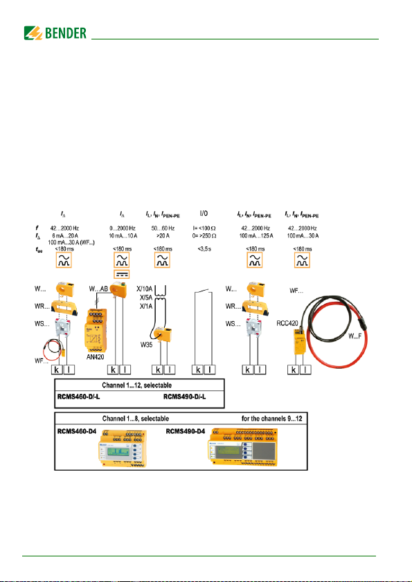
To measure AC/DC sensitive residual currents (according to IEC/TR 60755:
Type B) closed W…AB series measuring current transformers are required.
Six W…AB series measuring current transformers require one AN420 or
AN110 power supply unit.
For alternating and pulsating currents (according to IEC/TR 60755: Type A
W… (closed), WR… (rectangular), WS… (split-core) and WF… (flexible) series
measuring current transformers are used.
Any combination of the various measuring current transformer series can be
connected to the evaluator measuring channels.
Each RCMS460-D/-L and RCMS490-D/-L has 12 measuring channels. Up to 90
residual current monitors can be connected via a BMS bus (RS-485 interface
with BMS protocol), thereby up to 1080 measuring channels (sub-circuits) can
be monitored.
If this product is used for personnel protection, fire or plant protection, the frequency response can be set accordingly. The measured currents can be analysed
for harmonics. The THF can be determined too (THF =
T
otal Harmonic Factor).
The product must be adapted to local equipment and operating conditions
by making individual parameter settings, in order to meet the requirements
of applicable standards and to attain the protection goals.
14
RCMS460-490_D00067_03_M_XXEN/12.2017
Page 15

Safety instructions
In order to meet the requirements of the applicable stan dards, customised parameter settings must be made on the equipment in order to adapt it to local
equipment and operating conditions. Please heed the limits of the range of
application indicated in the technical data.
Any use other than that described in this manual is regarded as improper.
RCMS460-490_D00067_03_M_XXEN/12.2017
15
Page 16

Safety instructions
16
RCMS460-490_D00067_03_M_XXEN/12.2017
Page 17

3. System description
In buildings and industrial installations, a fault or failure of the power supply
involves high costs. In installations which require a high fault tolerance and
good safety, an RCMS system should constantly monitor the TN-S system for
insulation deterioration to ensure that the system is "clean" and electromagnetically compatible.
3.1 Typical applications
Measuring and evaluating residual, fault and rated currents of loads
and installations in the frequency range of 0…2000 Hz (W…, WR…,
WS…, WF… series measuring current transformers, 42…2000 Hz (W…,
WR…, WS…, WF… series measuring current transformers) (measuring
range see "Chapter 8.3 Technical data").
Monitoring of currents which can cause fires in flammable atmos-
pheres.
EMC monitoring of TN-S systems for "stray currents" and additional N-
PE connections.
Monitoring of N conductors for overload caused by harmonics
Monitoring of PE and equipotentional bonding conductors to ensure
they are free of current.
Residual current monitoring of stationary electrical equipment and sys-
tems to determine test intervals which meet practical requirements in
compliance with the accident prevention regulations BGV A3 (Ger-
many).
Personnel protection and protection against fire by rapid disconnec-
tion.
Monitoring of digital inputs.
RCMS460-490_D00067_03_M_XXEN/12.2017
17
Page 18

System description
3.2 Description of function
The currents are detected and evaluated as true r.m.s. value s in the fr equenc y
range of 0 (42)…2000 Hz. All channels are scanned simultaneously so that the
maximum scanning time for all channels is ≤180 ms if 1 x the response value
is exceeded and ≤ 30 ms if 5 x the response value is exceeded.
The latest current values of all channels are shown on the LC display in bar
graph format. If one of the two set response values is exceeded, the response
delay t
begins. Once the response delay has elapsed, the common alarm re-
on
lays "K1/K2" switch and the alarm LEDs 1/2 light up.
Two response values/common alarm relays, which can be set separately, allow a distinction to be made between prewarning and alarm. The faulty channel(s) and the associated measured value are indicated on the LC display. If
the current falls below the release value (response value plus hysteresis), the
release delay "toff“ t
mon alarm relays switch back to their initial state.
If the fault memory is enabled, the common alarm relays remain in the alarm
state until the reset button is pressed or a reset command is sent via the BMS
bus. The device function can be tested using the test button. Parameters are
assigned to the device via the LC display and the control buttons on the front
panel of one of the connected RCMS…-D devices or via connected panels,
Ethernet gateways (z. B. COM460IP) and Condition Monitors (z. B. COMTRAXX
CP700). With the adjustable preset function the response values can set for all
channels taking the latest measured value for each channel into account.
Digital input
Each individual channel can be used for one of the following monitoring functions:
– As digital input using a potential-free contact 1/0
– Or for current or residual current monitoring in combination with
measuring current transformers.
begins. When the release delay has elapsed, the com-
off
18
RCMS460-490_D00067_03_M_XXEN/12.2017
Page 19

System description
History memory in RCMS460-D, RCMS490-D
The device utilises a history memory for failsafe storing of up to 300 data records (date, time, channel, event code, measured value), so that all data about
an outgoing circuit or an area can be traced back at any time (what happened
when).
Analysis of harmonics
The analysis of the harmonics of the measured currents can be selected via a
menu item in RCMS460-D, RCMS490-D. There, the DC component, the THF
and the current value of the harmonics (1…40 at 50/60 Hz, 1…5 at 400 Hz) is
displayed numerically and graphically.
3.3 Device variants
RCMS residual current monitoring systems differ depending on the residual current monitor version used, RCMS460… or RCMS490….
RCMS460-D
Device version RCMS460-D utilises a backlit graphical display. This version is
used for local display of detailed information about all devices connected to the
bus in the control cabinet. This device can be used to parameterise all RCMS devices connected to the BMS bus and to display all measurement details. Several
RCMS-D devices can be used within one system.
RCMS460-L
Device version RCMS460-L utilises a two-digit 7-segment display where the
address of this device is displayed within the BMS bus. The alarm LEDs indicate
in which measuring channel the response value has been exceeded. Parameters
can be set via an RCMS…D, an
tion Monitor (z. B. COMTRAXX CP700).
Ethernet gateway (z. B. COM460IP) or a Condi-
RCMS490-D/RCMS490-L
The function of the device versions RCMS490-D/RCMS490-L corresponds to
the function described above. In addition, a galvanically isolated alarm contact (N/O contact) is available, e.g. for triggering a circuit breaker in this subcircuit when a response value is exceeded.
RCMS460-490_D00067_03_M_XXEN/12.2017
19
Page 20
System description
RCMS…-D4/RCMS…-L4
The function of device version RCMS…-D4/RCMS…-L4 corresponds to the
function described before. The functions of measuring channels k9 … k12
vary from those described before. They are exclusively designed for current
measurements with type A measuring current transformers (measuring range 100 mA … 125 A). For that reason, the measuring channels k9…k12 cannot
be used in c ombi nat ion w ith W…AB ser ies measuring current transformers or
as digital inputs.
Choice of RCMS and measuring channels
20
RCMS460-490_D00067_03_M_XXEN/12.2017
Page 21

4. Installation and connection
4.1 Unpacking
Unpack all the parts supplied with the system. Avoid sharp-edged tools
that may damage the content of the packaging.
Compare
received all products in full. The article numbers and type designation
printed on the nameplates provides an easy means of uniquely identifying
each device.
Check all parts supplied for any evidence of damage in transit. Equip-
ment damaged in transit must not be used. If a device has sustained
damage, please contact Bender. Details of who to contact are indicated
on the delivery documents.
When storing the devices in a cold environment as it is in winter, note
the following: Leave the devices to stand for 3 to 4 hours at room tem-
perature before connecting the power supply. When the devices are
moved from a cold to a warm environment, condensation will be evi-
dent on all parts. Putting damp devices into operation can result in
damage to electrical components and electric shock in case of contact.
your order with our delivery note to check that you have
RCMS460-490_D00067_03_M_XXEN/12.2017
21
Page 22

Installation and connection
4.2 Fuses, max. voltage, cable lengths
Equip the supply voltage of all system components with fuses.
IEC 60364-4-473 requires protective devices to be used to protect the
component in the event of a short circuit. We recommend the use of 6
A fuses.
When using busbar systems, please note: The maximum voltage of the
system being monitored must not exceed the nominal insulation voltage of the measuring current transformers used in the RCMS system.
Select the cables and cable lengths according to the technical data on
page 86ff. If you use cables that are longer than those specified here,
Bender cannot guarantee that the equipment will function safely.
For UL application:
– Use at least 60/70 °C copper lines!
4.3 Installation instructions
Danger of electric shock!
Before fitting the device and prior to working on the device
connections, make sure that the power supply has been
disconnected and the system is dead.
Furthermore, the electrical installation may sustain damage
and the device be destroyed beyond repair.
The devices are suitable for the following installation methods:
Distribution panels according to DIN 43871 or
DIN rail mounting according to IEC 60715 or
Screw mounting using M4 screws.
Mount the measuring current transformers in accordance with the notes in the
"Transformer installation“ technical information. When connecting the measuring current transformers, it is essential that you observe the maximum cable
lengths, the conductor cross section and that you use shielded cables.
22
RCMS460-490_D00067_03_M_XXEN/12.2017
Page 23
Installation and connection
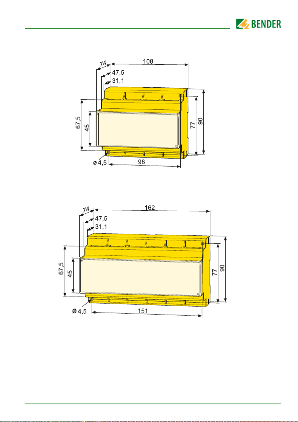
4.3.1 Dimension diagram RCMS460-…
4.3.2 Dimension diagram RCMS490-…
Dimensions in mm
RCMS460-490_D00067_03_M_XXEN/12.2017
23
Page 24
4.4 Connection
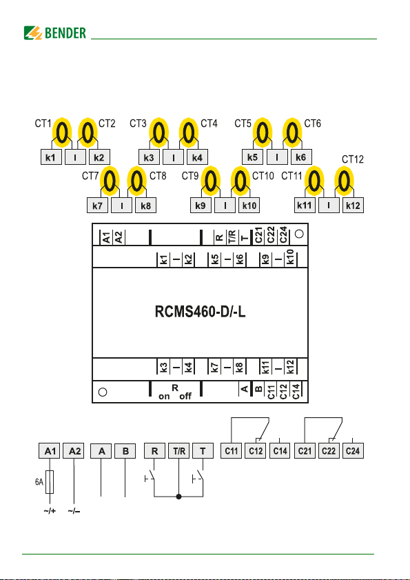
4.4.1 Wiring diagram RCMS460-…
Installation and connection
24
RCMS460-490_D00067_03_M_XXEN/12.2017
Page 25

Installation and connection
Legend to wiring diagram RCMS460-…
A1, A2 Connection of supply voltage US (see ordering informa-
tion):we recommend the use of 6 A fuses.
k1, l …
k12, l
A, B BMS bus (RS-485 interface with BMS protocol)
R, T/R External reset button (N/O contact). The external reset but-
T, T/R External test button (N/O contact). The external test buttons
C11, C12,
C14
C21, C22,
C24
R
on/off
CT Measuring current transformers (W…, WR…, WS…, WF…,
Connection to measuring current transformers CT1…CT12.
Either type A (W…, WR…, WS…, WF… series) or type B
(W…AB series) measuring current transformers can be selected for each measuring channel. When using up to six type B
measuring current transformers, an AN420-2 or AN110
power supply unit is required (for connections see page 29).
The channels k9…k12 of the device versions RCMS460-D4/L4 require the connection of type A measuring current
transformers.
tons of several devices must not be connected to one another.
of several devices must not be connected to one another.
Common alarm relay K1: Alarm 1, common message for
alarm, prewarning, device error.
Common alarm relay K2: ALARM 2, common message for
alarm, prewarning, device error.
Activate or deactivate the terminating resistor of the BMS
bus (120 Ω).
W…AB series)
RCMS460-490_D00067_03_M_XXEN/12.2017
25
Page 26
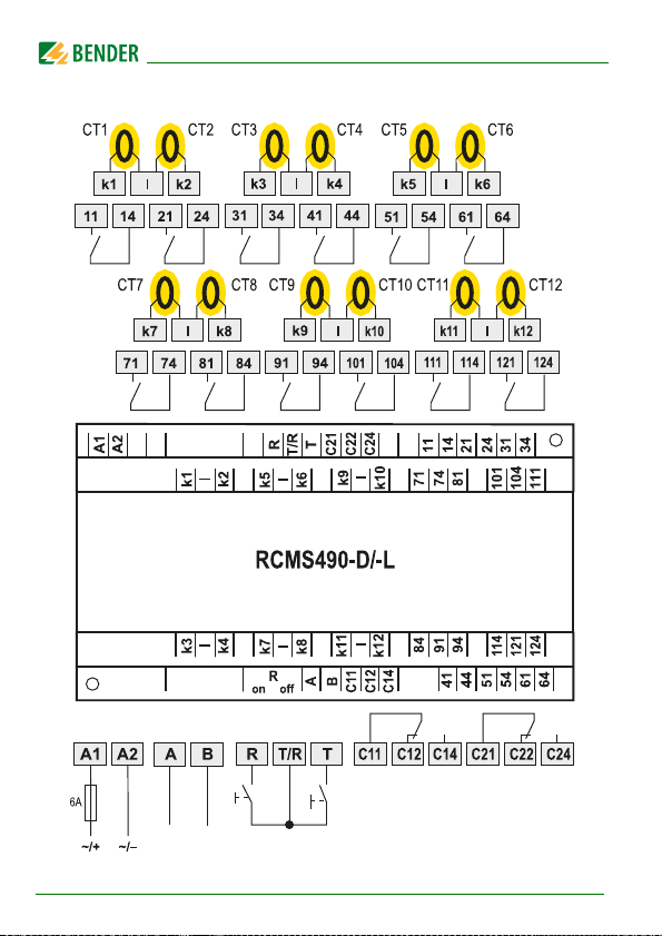
4.4.2 Wiring diagram RCMS490-…
Installation and connection
26
RCMS460-490_D00067_03_M_XXEN/12.2017
Page 27

Installation and connection
Legend to wiring diagram RCMS490-…
A1, A2 Connection of supply voltage US (see ordering information),
we recommend a 6 A fuse
k1, l …
k12, l
A, B BMS bus (RS-485 interface with BMS protocol)
R, T/R External reset button (N/O contact). The external reset but-
T, T/R External test button (N/O contact). The external test buttons
C11, C12,
C14
C21, C22,
C24
R
on/off
11, 14 …
121, 124
CT Measuring current transformers (W…, WR…, WS…, WF…,
Connection to measuring current transformers CT1…CT12.
Either type A (W…, WR…, WS…, WF… series) or type B
(W…AB series) measuring current transformers can be selected for each measuring channel. When using up to six type B
measuring current transformers, an AN420-2 or AN110
power supply unit is required (for connections see page 29).
The channels k9…k12 of the device versions RCMS490-D4/L4 require the connection of type A measuring current transformers.
tons of several devices must not be connected to one another.
of several devices must not be connected to one another.
Common alarm relay K1: Alarm 1, common message for
alarm, prewarning, device error.
Common alarm relay K2: Alarm 2, common message for
alarm, prewarning, device error.
Activate or deactivate the terminating resistor of the BMS
bus (120 Ω )
Alarm relay per channel: One N/O contact per measuring
channel (e.g. N/O contacts 11,14 for channel 1).
W…AB series)
RCMS460-490_D00067_03_M_XXEN/12.2017
27
Page 28
Installation and connection
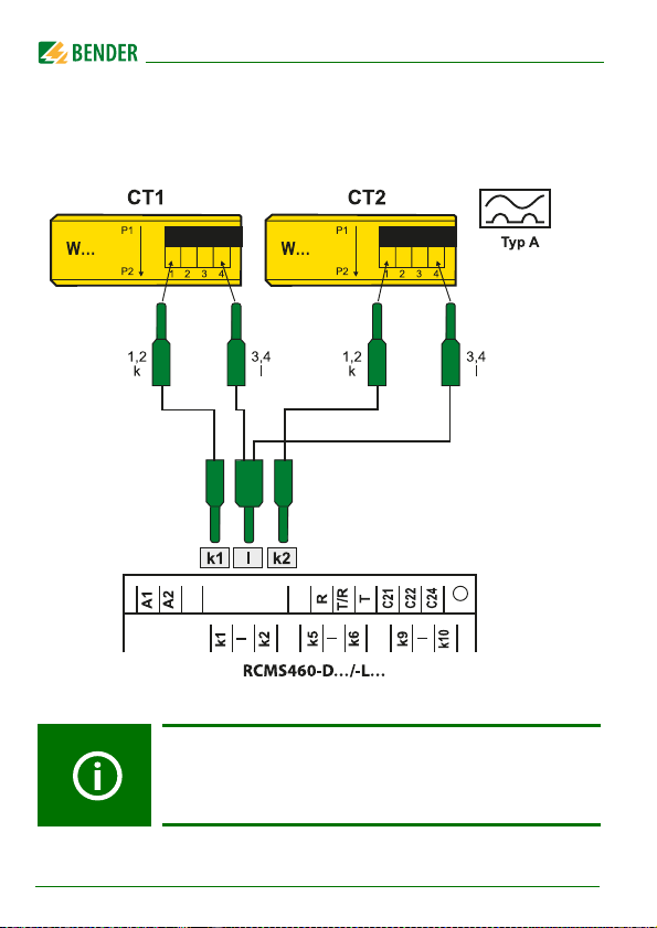
4.4.3 Connection of W…, WR…, WS… series measuring current transformers
Example: Connection W… series measuring current transformers
28
The terminals 1/2 as well as the terminals 3/4 are bridged
internally.
The connections k and l at the residual current monitor must
not be interchanged.
RCMS460-490_D00067_03_M_XXEN/12.2017
Page 29
Installation and connection
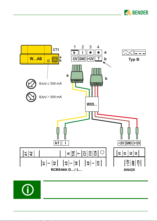
4.4.4 Connection W…AB series measuring current transformers (AC/DC current sensitive)
Coding
(not for W20AB)
The connections k and l at the residual current monitor must
not be interchanged.
RCMS460-490_D00067_03_M_XXEN/12.2017
29
Page 30

Installation and connection
Legend to W…AB series measuring current transformer
connection
W…AB AC/DC sensitive W…AB series measuring current transfor-
mers. Always adapt the measuring current transformers to
the maximum response value I(dn) (see wiring diagram).
WXS… Prefabricated connecting cable.
Colour code:
kyellow
l green
12 V black
GND brown
+ 12 V red
AN420 Power supply unit for supplying up to six W…AB series
measuring current transformers. Alternatively, an AN110
power supply unit can also be used.
Only if these notes are observed will you obtain a true
measurement result.
You must ensure that all live conductors are routed
through the measuring current transformer.
Do not use shielded conductors.
Do not route any PE conductors through the meas-
uring current transformer!
Commercial measuring current transformers are
not suitable for direct connection to the RCMS460/
RCMS490 systems and must not be used.
Additional information is available in our "Transformer
installation" manual.
30
RCMS460-490_D00067_03_M_XXEN/12.2017
Page 31

Installation and connection
4.4.5 Connection WF… series measuring current transformers
The connections k and l at the residual current monitor must
not be interchanged.
RCMS460-490_D00067_03_M_XXEN/12.2017
31
Page 32

Installation and connection
Legend to W…AB series measuring current transformer
connection
W…F Flexible WF… series measuring current transformers
RCC420 Signal converter
Commercial measuring current transformers are not
suitable for direct connection to the RCMS system and must
not be used.
Additional information is available in our "Transformer
installation" manual.
Only if these notes are observed will you obtain a true
measurement result.
4.4.6 Example for a system design – minimum system consisting of an RCMS460-D and 12 measuring points
Measuring current transformer
AC/DC sensitive (0...2000 Hz)
series
W...AB
series
W...AB
series
W...AB
series
W...AB
TN-S-System
Measuring current transformer
pulsed DC sensitive (42...2000 Hz)
distribution
board
series
W..., WR...,
WS..., WF...
series
W..., WR...,
WS...,
series
W..., WR...,
WS..., WF...
32
RCMS460-490_D00067_03_M_XXEN/12.2017
Page 33

Installation and connection
4.4.7 Example for a standard system design consisting of an RCMS460-D and RCMS460-L and a protocol converter COM460IP
COM465IP
COMTRAXX®
ON
ETHERNET/IP
MODBUS/RTU
BMS
RCMS460-D
RCMS460-L
AN420
COM465IP
U
S
AC 85…260 V
NL
DI-1DL
B/N A/P
B/N A/P
Legend to connection example
RCMS… Residual current monitors
AN420 When AC/DC sensitive W…AB series measuring current
transformers are used, an AN420 or AN110 power supply
unit is required that supplies up to six measuring current
transformers of this type. When the supply voltage of
AN110-1 is < 30 V, the output power decreases, so that only
five measuring current transformers can be connected.
COM460IP Protocol converter for connecting the BMS bus (Bender
measuring device interface) with a TCP/IP (Transmission
Control Protocol/Internet Protocol) network via Ethernet.
RCMS460-490_D00067_03_M_XXEN/12.2017
33
Page 34

Installation and connection
CT
a
b
DI-1DL The DI-1DL repeater only is required when the length of the
cable exceeds 1200 m or when more than 32 devices are
connected to the bus.
CT W…, WR…, WS…, WF…, W…AB series measuring current
transformers.
4.4.8 Connection digital input
a Potential-free contact
Status Resistance between k and l
0: > 250 Ω
1: < 100 Ω
b Measuring current transformer
34
RCMS460-490_D00067_03_M_XXEN/12.2017
Page 35

5. Commissioning
5.1 Before switching on
Note on opening the transparent front panel cover:
Take hold of the cover at the bottom edge and swivel it
upwards. The cover can also be removed completely. Once
the adjustments have been completed, the front panel cover
must be refitted.
1. Does the connected supply voltage U
on the device nameplates?
2. Only when busbar systems are used: Has the maximum permissible nominal insulation voltage of the measuring current transformers been observed?
3. Are you sure that the PE conductor has not been routed
through the measuring current transformer at any point?
4. In mounting the measuring current transformers, have any magnetic fields that are nearby and could cause interference been
taken into account?
5. Has the maximum permissible cable length for the measuring
current transformers been observed?
6. Is a 120-Ω resistor connected at the beginning and end of the
BMS bus?
7. Have the maximum permissible interface cable length (1200 m)
and number of BMS bus nodes (32) been observed?
8. Is address 001 and therefore the master function, assigned?
9. In respect of the BMS bus node address settings, has each
address only been assigned once?
RCMS460-490_D00067_03_M_XXEN/12.2017
match the information
S
35
Page 36

Commissioning
5.2 Switching on
1. Connect the supply voltage of all devices connected to the BMS bus.
Initially, the "ON" LED flashes on the RCMS… and the RCMS460…-D
graphic display shows the (Bender) welcome screen. The "ON" LED
then lights up permanently.
2. Set the BMS bus addresses. Never assign one address twice. Check, if
address 001 and thus the master function has been assigned.
3. Select the language (see page 71).
4. Set the CT type for each channel (page 66).
5. Start the preset function (see page 56).
6. Switch off unassigned measuring channels to avoid device errors (see
page 63).
7. Fault messages may be caused by measuring current transformers not
being connected. Check the measuring current transformer connections. Switch off the CT monitoring of the measuring channels not currently used (see page 67).
8. Eliminate insulation faults and the associated fault messages. If a response value is exceeded or device error messages occur, this is indicated on the RCMS… by means of the alarm LEDs lighting up and an
associated message appearing on the graphic display (RCMS…-D
only).
– You can find information about the alarms on the RCMS460…-D in
the "Alarm/Meas. values" menu. Information on the RCMS…-L can
be displayed via the BMS master.
– Eliminate the insulation faults detected by the RCMS. Check whe-
ther the set response values are correct and practical for this system. If you want to readjust all response values, use the preset
function of the device.
– The RCMS…-D displays any device errors that have occurred. The
RCMS…-L… displays an error code. If a device error continues to
exist after a reset has been carried out, the RCMS… has to be
replaced.
36
RCMS460-490_D00067_03_M_XXEN/12.2017
Page 37

6. Operation
1
2
3
6
5
4
7
8
6.1 Operating and display elements RCMS460…-D
LINETRAXX®
1
2
3
4
5
6
7
8
RCMS460-490_D00067_03_M_XXEN/12.2017
RCMS460-D
The "ALARM 2“ LED lights up if the measured value falls below or
exceeds the "Alarm" response value in a measuring channel or
until an error is indicated by the digital input.
The "ALARM 1" LED lights up if the measured value falls below or
exceeds the "prewarning" response value in a measuring channel
or in case of a device error.
LED "ON“ lights up when the device is switched on and
switching on.
"INFO" button: to call up standard information
ESC button: to exit the menu function without changing
"TEST" button: to call up automatic test
Up button: to change parameters, scroll
"RESET" button: to acknowledge alarm and fault messages
Down button: to change parameters, scroll
"MENU" button: to toggle between the standard display, menu
and alarm display
Enter button: to confirm parameter changes
Illuminated graphic LCD
flashes until the device is ready for operation during
parameters
RCMS490-D
37
Page 38

6.2 Operating and display elements RCMS…-L
1
2
3
6
5
4
7
8
9
Operation
LINETRAXX®
1 The "ALARM 2“ LED lights up if the measured value falls below or
2 The "ALARM 1" LED lights up if the measured value falls below or
3 LED "ON“ lights up when the device is switched on and flashes until
4 ESC button: to exit the menu function without changing parameters
5 "TEST" button: to call up automatic test
6 "RESET" button: to acknowledge alarm and fault messages
7 "SET" button: to set the BMS address
8 Alarm-LEDs "1…12“ light up if an insulation fault has been detected
9 Digital display for device address and error codes.
RCMS460-L
exceeds the "Alarm" response value in a measuring channel or until
an error is indicated by the digital input.
exceeds the "prewarning" response value in a measuring channel or
in case of a device error.
the device is ready for operation during switching on.
Up button: to change parameters, scroll
Down button: to change parameters, scroll
"ENTER" button: to confirm parameter changes
in the relevant measuring channel
or flash if there is a fault with the measuring current transformer.
RCMS490-L
38
RCMS460-490_D00067_03_M_XXEN/12.2017
Page 39

Operation
100%
50%
k 1 2 3 4 5 6 7 8 9
10 11
12
0%
Channel disabled
Channel enabled
Channel enabled,
current is flowing
(height ≥ 2 graduation m
(height = 1 graduation m
6.3 Working in operating mode
6.3.1 Standard display
In operating mode, you will see a bar graph on the RCMS460…-D display. For
each of the 12 measuring channels, it shows what percentage of the set alarm
value I
For digital inputs 100 % = 1 and 0 % = 0.
The RCMS…-L shows its BMS bus address (e.g. 02). Only the green "Power ON"
LED is lit.
6.3.2 Alarm and its effect
Possible causes of alarm messages:
The value falls below or exceeds the set response value or the prewarn-
Digital input closed resp. open
Fault measuring current transformer or CT connection fault
Device error (see „Display device error“ on page 82)
(alarm) and I
Δn2
(prewarning) has been reached.
Δn1
ing threshold during current or residual current measurement.
The RCMS460… signals prewarning and/or alarm:
LED "ALARM 1" (prewarning) and/or LED "ALARM 2" (alarm) light
depending on the type of alarm.
Associated common alarm relays (C…) switch.
RCMS490… only: Alarm relays of the individual channel switch.
An alarm message is being sent on the BMS bus.
RCMS460-490_D00067_03_M_XXEN/12.2017
39
Page 40

Operation
ALARM 1/1
Residual current
130 mA
Addr.: 2 Chan.: 12
An entry is made in the history memory.
An entry is made in the history memory.
RCMS…-D…: An alarm message is shown on the display.
Line 1: ALARM, PREWARNING or FAULT
Alarm 1 of 1 pending alarms
Line 2: Alarm status and alarm text: (e.g. residual current, digital in-
put, no Master, CT connection).
No alarm
Prewarning
Alarm, fault
Line 3: r.m.s. value
Line 4: BMS bus address of the RCMS and measuring channel on
which the alarm has occurred.
RCMS…-L…: The alarm LED of the affected measuring channel lights
up.
40
RCMS…-D4/-L4 only (channels 9…12):
When measuring the load current, a prewarning is indicated
in case of overcurrent only. In case of undercurrent a
prewarning is not indicated.
RCMS460-490_D00067_03_M_XXEN/12.2017
Page 41

Operation
Auto test
TEST 12/12
Residual current
100 mA
Addr.: 2 Chan.: 12
6.3.3 Test procedure
A test serves to check the device function (hardware components) of the
RCMS. A test can be activated as follows:
Select standard display and then press the "TEST" button on the RCMS
front panel for at least one second.
Press an external test button connected to the RCMS…
Send a test command via the BMS bus.
RCMS…-D… only: Select "TEST" from the control menu.
The RCMS… responds as follows:
"ALARM 1" and "ALARM 2" LEDs light up.
All alarm relays switch (this function can be deactivated, refer to
page 68).
An alarm message is sent on the BMS bus.
An entry is stored in the history memory with the suffix "TEST".
RCMS…-D…: The progress of the test is indicated on the display.
The RCMS460…-D then displays the set response value for the highest
functioning measuring channel.
Press the "" button several times to display the correct functioning of
the other measuring channels.
RCMS460-490_D00067_03_M_XXEN/12.2017
41
Page 42

Operation
RCMS…-L…: All alarm LEDs light for approx. 10 seconds.
After successful testing, all LEDs must go out again, with the exception of the
LED "ON" and the alarm relays must return to their initial position.
6.3.4 Resetting saved alarm messages (RESET)
If the fault memory is enabled, the alarm status will remain, even after the
cause of the fault has been eliminated, until a "RESET" is carried out.
RCMS…-D… only: First press the "ESC" button to exit the display of the current alarm message. The "RESET" button cannot be pressed before the standard display appears (bar chart).
A reset can be carried out in the following way:
Select standard display and then press the "RESET" button on the RCMS
front panel for at least one second.
Press an external reset button connected to the RCMS…
Send a reset command via the BMS bus.
RCMS…-D… only: Call the "RESET" function in the Control menu.
Saved alarm messages that are no longer pending are deleted. The alarm relay
drops out, the alarm LEDs go out and there are no longer any alarm messages
on the BMS bus.
42
RCMS460-490_D00067_03_M_XXEN/12.2017
Page 43

Operation
RESET
RCMS460-D
10.03.16 12:59
Address :2
Software: D233V2.50
The RCMS…-D shows the progress of the reset operation.
6.3.5 Displaying standard information
This function is only available in RCMS…-D. Press the "INFO" button. You will
now see information relating to the device and software on the RCMS…-D display. Use the "" arrow button to scroll all the information. Please have this
information to hand if you should need to contact us for assistance by telephone.
Line 1: Device type
Line 2: Date, time
Line 3: BMS bus address of the RCMS
Line 4: Software version D233V… for measuring technology proc-
esses
Line 5: Date of the measurement technique software version
Line 6: Software version D216/D256/D339/D403… for
communication processes
Line 7: Date of communication software version
Line 8…10: Bender address, homepage
Line 11: Exit. Exit standard information.
RCMS460-490_D00067_03_M_XXEN/12.2017
43
Page 44

Operation
6.4 Setting the RCMS…-L…
RCMS…-L has a 7-segment LED display. Operation and setting can be carried
out via an RCMS…-D or using the following devices: MK2430, MK800,
COM460IP or CP700. The harmonics analysis and the preset function can only
be carried out in conjunction with an RCMS…-D. Only the BMS bus address
can be set directly on the RCMS…-L.
The following functions and settings are not included in the RCMS…-L :
– Language – Time/date
– Data logger – Interface menu
– History memory – Password
Setting the BMS bus address of the RCMS…-L
1. Press the "SET" button for approximately two seconds to open the
main menu. The BMS bus address flashes.
2. Use the arrow buttons ", " to select the required address.
3. Press the Enter button "↵" to confirm this setting.
4. If you wish to exit the setting without making a change, press the "ESC"
button.
6.5 Operation and setting of the RCMS…-D…
This chapter describes the RCMS…-D menu mode.
The RCMS…-L only has some of these functions available (see „Setting the
RCMS…-L…“ on page 44). This also applies if an RCMS…-D is used to operate
and set an RCMS…-L.
44
RCMS460-490_D00067_03_M_XXEN/12.2017
Page 45

Operation
Exit
1.Alarm/meas.values
2.% Bar graph
3.History
Enter
password:
0 0 0
6.5.1 Opening the main menu
Press the "MENU" button to open the main menu.
In the main menu, use the following buttons:
ESC Exit this function without storing or go up one menu level.
, Select menu items
↵ Confirm selected menu item (Enter).
The menu mode is exited automatically if no button is
pressed for longer than five minutes. Exceptions: The "Test"
and "Test communication" functions.
Settings can be password protected. When an attempt is
made to change settings, the password entry screen appears
automatically:
Details see “Settings menu 11: Password” on page 73.
If you can't remember your password, contact the Bender
Service.
RCMS460-490_D00067_03_M_XXEN/12.2017
45
Page 46

6.5.2 Menu overview diagram
7.Control
8.External devices
9.Info
4.Relay
6.Data logger
7.Language
8.Interface
9.Alarm addresses
10.Clock
11.Password
12.Factory setting
13.Service
Exit
1.TEST
2.RESET
3.Test communication
Exit
Exit
5.History
Exit
1.Alarm/meas.values
3.History
2.% Bar graph
4.Harmonics
5.Data logger
6.Settings
1.General
Exit
2.PRESET
3.Channel
Operation
46
RCMS460-490_D00067_03_M_XXEN/12.2017
Page 47

Operation
6.5.3 Main menu functions
Menu item Function Page
Exit Exit menu mode -
1.Alarm/
meas.values
Displays the following for each measuring
channel, if applicable,: prewarning, alarm,
49
measured value, digital input status, response value, channel disabled, CT connection fault.
2.% Bar graph For each of the 12 measuring channels the
49
reached per cent value of the set alarm
value I
(alarm) and I
Δn2
(prealarm) is indi-
Δn1
cated. In case of digital inputs, the status is
indicated.
3.History Displays the history (300 data records) with
50
information about messages, acknowledgements and associated times. Displays the
minimum and maximum residual current
after an alarm has occurred, with address
and channel.
4.Harmonics Displays the following for the selected
51
measuring channel: measured value, THF
(Total Harmonic Factor) in %; DC component, fundamental oscillation and harmonics in mA.
5.Data logger Displays the recorded measured values (300
52
data records) for each measuring channel.
6.Settings Settings for this RCMS… are made here. 53
RCMS460-490_D00067_03_M_XXEN/12.2017
47
Page 48

Operation
Menu item Function Page
7.Control This menu offers various control options,
8. External
devices
9.Info Information on the device. The same display
such as TEST, RESET, Test communication.
Settings on devices externally connected to
the BMS bus
(e.g. RCMS460-D/-L, RCMS490-D/-L).
is obtained by pressing the INFO button in
the operating mode (refer to „Displaying
standard information“ on page 43).
74
76
79
48
RCMS460-490_D00067_03_M_XXEN/12.2017
Page 49

Operation
I(d) I(dn)
1. 4mA 10mA
2. 120mA 20mA
3.
Channel disabled
100%
50%
k 1 2 3 4 5 6 7 8 9
10 11
12
0%
Channel switched off
Channel enabled
Channel enabled,
current is flowing
(height ≥ 2 graduation m
(height = 1 graduation m
6.6 The main menu
6.6.1 Menu 1: Alarm/meas. values
RCMS…-D… displays the following for each measuring channel: alarm, measured value, response value.
Column 1: Channel number 1…12
Column 2: Alarm status:
Column 3: I(d): The currently measured r.m.s. value of the residual cur-
rent I
Column 4: I(dn): Set response value (rated residual operating current)
I
Δn
or "Channel disabled“ or "CT connected“.
6.6.2 Menu 2: % Bar graph
For each of the 12 channels the RCMS…-D… shows the reached response value in per cent and/or the status of the digital inputs.
No alarm
Prewarning
Alarm, fault
, the load current or the status of the digital input.
Δ
, digital input
100 % Response value (alarm) resp. digital input = 1
50 % Prewarning (here set to 50 %)
0 % Channel disabled resp. digital input = 0
RCMS460-490_D00067_03_M_XXEN/12.2017
49
Page 50

Operation
History no. 297
Start:
01.03.16/15:57:00
Ack.:
End:
01.03.16/16:07:03
History no. 297
Residual current
Min. 21mA/Max.198mA
Addr.:2 Chan.:1
6.6.3 Menu 3: History
The failsafe history memory stores up to 300 events (prewarnings, alarms,
tests). If the history memory is full, the oldest entry will be deleted in each case
in the event of an alarm, to create space for the new entry.
For details about erasing the entire history memory refer to „Settings menu 5:
History“ on page 70.
Line 1: Event number (if applicable): TEST.
Line 2: Event start: Date/time
Line 3: Event acknowledgement (e.g. by pressing
"Buzzer off" at TM…, MK2430, MK800):
Line 4: Event end: Date/time
1. If you are searching for an event that occurred at a specific time, use
the arrow buttons to navigate to the required entry.
2. Press the "↵" button to call up details about the current entry in the history memory.
Date/time
Line 1: Data record number
Line 2:
50
Alarm status and alarm text (e.g. residual current, digital input,
overcurrent at k9…k12 (RCMS…-D4/-L4 only)
No alarm
Prewarning
Alarm, fault
RCMS460-490_D00067_03_M_XXEN/12.2017
Page 51

Operation
Channel:1
1
21mA
THF 3%
DC 3mA
1.
85mA
Line 3: Minimum and maximum measured value after an alarm has
Line 4: Address and measuring channel of the device sending the
occurred.
message.
6.6.4 Menu 4: Harmonics
The analysis of the harmonics of the measured currents is displayed as a bar
and a current value. Harmonics are multiples of the rated frequency.
Example: Rated frequency = 50 Hz, 2nd Harmonics = 100 Hz.
The RCMS…-D… can only determine the harmonics currents correctly if the
selected rated frequency in menu "6. Settings-> General-> Rated frequ." suits
the current being monitored.
At 50 o r 60 Hz, the cur ren t v alu e of harmonics 1…40 is displayed; at 400 Hz the
current value of harmonics 1…5 is displayed.
THF: The total harmonic factor (THF) specifies the ratio of the har-
monics r.m.s value of an alternating quantity to the fundamental r.m.s. value. The smaller the THF, the more sinusoidal
the current signal.
If 50 or 60 Hz are selected in the "Cut-off frequency" menu
(see page 65) the THF cannot be determined. The display
indicates „- - -“ .
An analysis of the harmonics cannot be carried out in
disabled channels or channels with digital input. The display
indicates „- - -“ .
RCMS460-490_D00067_03_M_XXEN/12.2017
51
Page 52

Operation
Exit
1.Data logger
2.Data logger
3.Data logger
Column 1: Identifies the THF, DC component and harmonics number.
Column 2: Bar graph indication of the THF (% of the r.m.s. value),
Column 3: Current r.m.s. value, THF/residual current of this measuring
Select a measuring channel for displaying the harmonics:
– Use the "" button to go to the measuring channel setting. Press
– Use the Up/Down buttons to select a measuring channel. Press "↵"
3. You can use the Up/Down buttons to browse the harmonics current
values of this measuring channel.
bar graph of the current value.
channel. Harmonics current values are updated in order. Updating all harmonics takes up to 15 seconds.
the "↵" button.
to confirm your selection.
6.6.5 Menu 5: Data logger
Up to 300 data records can be recorded for each of the 12 measuring channels. A new measured value is saved if it differs from the previous measured
value by a defined percentage. You define this percentage in the menu "6.
Settings-> 5. Data logger -> Change". You also make settings for overwriting
and deleting measured values here.
52
RCMS460-490_D00067_03_M_XXEN/12.2017
Page 53

Operation
271 01.04.16 15:57:03 35mA
270 01.04.16 15:40:10 51mA
269 01.04.16 15:37:15 36mA
268 01.04.16 15:35:01 70mA
1. Use the Up/Down buttons to select the required measuring channel
(measuring channel number k1…k12). Press the "↵" button.
2. You can use the Up/Down buttons to browse the recorded data
records of this measuring channel (data record number, date, time,
measured value or digital input).
6.6.6 Menu 6: Settings
The following menu items are available for configuring the RCMS:
Menu item Function Page
Exit Exit settings -
1.General Set the fault memory, prewarning, hysteresis, frequency and start-up delay.
2.PRESET Default setting of all response values to a
specified factor and offset value. In case of
digital inputs the current status (0/1) will be
reversed.
3.Channel Set for each measuring channel: factor, response value, function (overcurrent/ undercurrent), digital input or channel "off",
response delay, release delay, cut-off fre-
RCMS460-490_D00067_03_M_XXEN/12.2017
quency, CT type and transformer monitoring.
54
56
58
53
Page 54

Operation
Menu item Function Page
4.Relay Set the relay mode of operation and type of
5.History Delete the history memory. 70
6.Data logger Set change in %, activate/deactivate over-
7.Language Select the language for menu and alarm
8.Interface Set the RCMS…-D own BMS bus address. 71
9.Alarm
addresses
10.Clock Set date format, date, time and summer
11.Password Changing and activating the password. 73
12.Factory setting
13.Service For Bender service employees only. 73
fault that you wish to cause a switching operation for the common alarm relay.
write data, delete data.
texts.
Setting of bus addresses for devices whose
alarm messages are to be displayed on this
RCMS…-D.
time changeover.
Resets all settings to factory settings. 73
68
70
71
71
72
6.6.6.1 Settings menu 1: General
In this menu you make settings that apply to this device and therefore to all
measuring channels.
54
RCMS460-490_D00067_03_M_XXEN/12.2017
Page 55

Operation
1. Fault memory
Faults that only occur temporarily can be saved.
on After eliminating the cause of fault all alarm messages remain
off RCMS… exits the alarm mode as soon as the cause of fault is
stored until a reset is carried out.
eliminated.
2. Prewarning
Setting as a percentage of the response value. Setting range: 10…100 %,
resolution of setting 1%.
3. Hysteresis
If the measured value were to oscillate around the response value, the
RCMS… would constantly change from alarm to normal status and back
again. If a hysteresis of 20 % is set, the alarm status is not exited until the measured value is 20 % below resp. above the response value.
Setting range: 2…40 %, resolution of setting 1%.
4. Frequency
Select the rated frequency of the monitored current. Only if the setting is correct, can the RCMS… determine the harmonics currents properly.
Setting options: DC, 50 Hz, 60 Hz, 400 Hz.
RCMS460-490_D00067_03_M_XXEN/12.2017
55
Page 56

Operation
Exit
1.Factor: *3
2.Offset: 30 mA
3.PRESET
5. Start-up delay t
Time delay after the RCMS… is switched on.
No alarm messages are generated during this period. This time delay is required if the RCMS…-D and the monitored system are switched on simultaneously. Currents caused by switching actions are ignored.
Setting range: 0…99 s. Resolution of settings as follows:
Setting range Resolution of setting
0…50 ms 5 ms
60…200 ms 10 ms
250…500 ms 50 ms
600 ms …2 s 100 ms
2.5…5 s 0.5 s
6…20 s 1 s
25…50 s 5 s
60…99 s 10 s
6.6.6.2 Settings menu 2: PRESET
Default setting of all response values to a specified factor and offset value. This
default setting facilitates commissioning of new installa tions. Alarm messages
as a result of not previously set response values can be avoided. The new response value is determined as follows:
1. The currently measured value is multiplied by the appropriate factor.
2. The specified offset value is added.
Displayed by a formula:
Response value = (currently measured value x factor) + Offset
56
RCMS460-490_D00067_03_M_XXEN/12.2017
Page 57

Operation
1. Factor (for PRESET)
Set the multiplication factor for the latest measured value. Setting range:
1…99 %, resolution of setting 1 %.
Recommended setting (factory setting): Factor 3
2. Offset (for PRESET)
Set the offset value that is to be added to the product of the "current measured value x factor". Setting range: 0…20 A, resolution of setting:
Setting range Resolution of setting
0…20 mA 1 mA
25…50 mA 5 mA
60…200 mA 10 mA
250…500 mA 50 mA
600 mA… 2 A 100 mA
2.5 A…5 A 0.5 A
6 A…20 A 1.0 A
Recommended setting (factory setting): Offset 30 mA
3. PRESET
If the RCMS… is used as a means of protection to ensure
personnel and fire protection, the PRESET function must
not be used!
There is the risk that the selected response values are too
high.
Make sure that all existing insulation faults are eliminated
before using the preset function!
There is the risk that the selected response values are too
high.
RCMS460-490_D00067_03_M_XXEN/12.2017
57
Page 58

Operation
Chan.: 1
Exit
1.Factor: *1
2.Resp. val.:100mA
Setting an
individual channel:
Chan.: 1..12
Exit
1.Factor: --
2.Resp. val..:--
Setting
all channels:
Presetting is carried out for all measuring channels on this device.
Exceptions:
When a channel is disabled, the set response value does not change.
When the current measured value is 0 mA, the smallest possible
response value is set:
– Type A measuring current transformer : 6 mA
– Type B measuring current transformer : 10 mA
If the PRESET routine determines a value that exceeds the maximum
response value (type A: 20 A, type B: 10 A) the highest possible
response value is set.
For digital inputs the current status (0/1) will be reversed.
To prevent unwanted execution of this function, the entry must be confirmed
once more.
6.6.6.3 Settings menu 3: Channel
You make the measuring channel settings in this menu (either individually or
for all channels (1…12) simultaneously). Selecting a measuring channel:
1. Use the "" button to go to the measuring channel setting. Press the
"↵" button.
2. Use the Up/Down buttons to select a single measuring channel (e.g. 1)
or all measuring channels (1…12). Press "↵" to confirm your selection.
58
RCMS460-490_D00067_03_M_XXEN/12.2017
Page 59

Operation
If the measuring channel settings only differ slightly, we
recommend to proceed as follows:
- first set all the measuring channels (1…12) to the same
value
- then modify the setting of an individual measuring channel.
1. Factor (for measuring current transformers)
Setting of a factor to adapt the RCMS… to connected measuring current
transformers. The following factor setting ranges are available depending on
the CT type and the application. When the channel is disabled, this setting
menu has no function (display: --).
Select:
*1 For Bender measuring current transformers (W…, WR…,
*1 … *250 For measuring current transformers with a different transfor-
/2 … /10 If the conductor to be m onitored is wound through the meas-
WS…, WF…, W…AB).
mation ratio (e.g. if third-party measuring current transformers are connected via a Bender measuring current
transformer).
uring current transformer several times in order to amplify
the signal.
Examples for the factor determination
X = transformation ratio, N = number of turns through the measuring current
transformer (wire up)
Example 1: Bender measuring current transformers with a
transformation ratio of 600/1
Factory setting:
Factor: *1, CT monitoring: on
RCMS460-490_D00067_03_M_XXEN/12.2017
59
Page 60

Operation
Example 2: Connection of external Bender measuring current
transformers
Bender-Messstromwandler
BenderMessstromwandler
Settings:
Factor = (X / N)
Measuring current transformer monitoring: On
= 100/1
= *100
60
RCMS460-490_D00067_03_M_XXEN/12.2017
Page 61

Operation
Example 3:
The wire to be monitored is "wound" several times through the
Bender current transformer in order to amplify the signal
Setting:
Factor: /3
Measuring current transformer monitoring: On
2. Response value
The response value is the value at which an alarm is output. In case of digital
inputs, set the status (0 or 1) at which an alarm is to be signalled.
Tolerances have to be taken into account (measuring current
transformers, RCMS…) whenever measurements are carried
out. The IEC 62020 specifies that the set response value shall
not be exceeded, therefore an RCMS… shall respond when
50…100 % of the set response value are reached.
Prewarning is therefore to be signalled earlier (x % of
50…100 % of the response value).
The current measuring channels k9…k12 of version
RCMS…-D4/-L4 have positive tolerances as regards the
response values.
RCMS460-490_D00067_03_M_XXEN/12.2017
61
Page 62

Operation
Depending on the settings in the "Channel -> Mode" menu and "Channel ->
CT" menu the following response values can be selected:
Type AB 10 mA…10 A (DC…2000 Hz)
Type A 6 mA…20 A (42…2000 Hz)
Flex. 100 mA…30 A (42…2000 Hz)
Digital inputs 0/1
Resolution of setting type AB
(AC/DC sensitive measuring current transformers):
Measuring current transformers W20AB measure residual
currents in the range AC/DC 10…500 mA.
Setting range Resolution of setting
10…20 mA 1 mA
25…50 mA 5 mA
60…200 mA 10 mA
250…500 mA 50 mA
600 mA… 2 A 100 mA
2.5 A…5 A 0.5 A
6 A…10 A 1.0 A
Resolution of settings type A
(pulsating current sensitive measuring current transformers):
Setting range Resolution of setting
6…20 mA 1 mA
25…50 mA 5 mA
60…200 mA 10 mA
250…500 mA 50 mA
600 mA… 2 A 100 mA
2.5 A…5 A 0.5 A
6 A…20 A 1.0 A
62
RCMS460-490_D00067_03_M_XXEN/12.2017
Page 63

Operation
Resolution of settings type A (RCMS…-D4/-L4 only, channels k9…k12):
Setting range Resolution of setting
100…200 mA 10 mA
250…500 mA 50 mA
600 mA… 2 A 100 mA
2.5 A…5 A 0.5 A
6 A…20 A 1.0 A
25 A…50 A 5.0 A
60 A…125 A 10.0 A
Resolution of settings type Flex.: the same as for type A
3. Function
Monitoring the measuring channel for overcurrent or undercurrent. Use of the
measuring channel as digital input. Unused measuring channels have to be
disabled.
> Alarm when the response value is exceeded.
< Alarm when the value falls below the set response value.
0/1 Use of the measuring channel as digital input.
off Measuring channel disabled.
* Scanning time digital inputs < 3.5 s.
Potential-free contact > 250 Ω, LC display indication: "0"
Potential-free contact < 100 Ω LC display indication: "1"
RCMS460-490_D00067_03_M_XXEN/12.2017
63
Page 64

Overview of available functions
Operation
RCMS…-
D4/-L4,
Channel
1…8
Measuring function
(selectable)
I/I
: 6 mA…20 A
Δn
RCMS…-D/-L
Channel
1…12
</>/OFF </>/OFF ---
(42…2000 Hz)
type A
I: 100 mA…125 A
--- --- </>/OFF
(42…2000 Hz)
I/I
: 10 mA…10 A
Δn
</>/OFF </>/OFF ---
(0…2000 Hz)
type B
1/0 1/0/OFF 1/0/OFF ---
4. Response delay t(on)
Response delay starts when a new alarm has been triggered.
Setting range: 0…999 s.
Resolution of settings:
Setting range Resolution of setting
0…50 ms 5 ms
60…200 ms 10 ms
250…500 ms 50 ms
600 ms …2 s 100 ms
2.5…5 s 0.5 s
6…20 s 1 s
25…50 s 5 s
60…200 s 10 s
250…500 s 50 s
600…999 s 100 (99) s
RCMS…-
D4/-L4,
Channel
9…12
64
RCMS460-490_D00067_03_M_XXEN/12.2017
Page 65

Operation
5. . Delay on release t(off)
If the condition that triggered the alarm does not exist anymore, the RCMS…
terminates its alarm once the release delay has elapsed.
Setting range: 0…999 s. Resolution of settings: the same as for response delay
t(on).
6. Cutoff frequency
Set the characteristics for the frequency response of residual current measurement I
The frequency response of the equipment can be set for a linear frequency response (up to the maximum frequency of 2000 Hz) if used for fire protection
or for a frequency response in accordance with IEC 60990 for personnel protection. For plant protection, the residual current is measured up to the rated
system frequency. The figure below shows the corresponding frequency response.
and current measurement I.
Δn
Param. Objective
50 Hz Plant protection: Only evaluates the fundamental compo-
nent of the current measurement.
60 Hz Plant protection: Only evaluates the fundamental compo-
nent of the current measurement.
IEC Personnel protection in accordance with IEC 60990 (touch
None Fire protection: Response factor remains the same over the
current for let-go): Above 200 Hz (approx.), the set response
value increases corresponding to the frequency-dependent
threshold according to IEC 60990.
entire frequency range.
RCMS460-490_D00067_03_M_XXEN/12.2017
65
Page 66

Frequency response
(cut-off frequency)
50 Hz 60 Hz
IEC
none
Response factor
I(d)
I(dn)
Operation
Response factor =
I(d) Residual current I
I(dn) Rated residual operating current I
: r.m.s. value currently measured
Δ
: Set response value
Δn
7. CT
Set the type of measuring current transformer.
Type A Pulsating current sensitive W…, WR…, WS…
series measuring current transformers
Flex. Flexible WF… series measuring current trans-
formers
Type AB AC/DC sensitive W…AB series measuring cur-
rent transformers
66
RCMS460-490_D00067_03_M_XXEN/12.2017
Page 67

Operation
8. CT monitor.
Enable or disable the measuring current transformer connection monitoring.
on Measuring current transformer connection is monitored.
Connection interruption, short-circuit or failure of the power supply
unit generate an alarm message after 20 seconds at the latest (W…AB
series) (Fault: CT connection). The "ALARM 1" LED lights up.
off Measuring current transformer connection is not monitored.
Flexible WF… measuring current transformers only:
CT monitor setting "off" must not be changed. If this is not
taken into account, the device signals a fault: "CT
monitoring".
9. Relay mode (RCMS490-D…/-L… only)
These devices have an alarm relay for each measuring channel (N/O contact).
Set the relay mode of operation for each relay.
N/O N/O operation. Relay only switches in the event of an alarm.
N/C N/C operation. Relay only switches in the event of an alarm.
N/O-T N/O operation. Relay switches when there is an alarm or a
N/C-T N/C operation. Relay switches when there is an alarm or a
off* Contacts of the relay are always open.
on* Contacts of the relay are always closed*.
* This function can also be activated via the BMS bus. By sending the command
"off" or "on" via the BMS bus, the switching of the relay can be activated. This
relay does not respond to alarms. It on ly serves as a signal converter (BMS-bus
signals/relay contact signals.
test.
test.
If the relay settings only differ slightly, we recommend the
following procedure for the RCMS490:
- first set all the relays (1…12) to the same value;
- then modify the settings of individual relays.
RCMS460-490_D00067_03_M_XXEN/12.2017
67
Page 68

Operation
Relay: 1
Exit
1.Mode of operation:N/O
Set a
single relay:
Relay: 1..2
Exit
1.Op.mode
2.Alarm: --
Set both
relays:
6.6.6.4 Settings menu 4: Relay
In this men u, yo u se t the com mon a lar m rel ays K1 (C 11, C12, C14 ) and K2 ( C21,
C22, C24), either individually or both alarm relays. Select the relay:
1. Use the "" button to go to the relay channel setting. Press the "↵"
button.
2. Use the Up/Down buttons to select a relay (1, 2) or both relays (1…2).
Press "↵" to confirm your selection.
68
RCMS460-490_D00067_03_M_XXEN/12.2017
Page 69

Operation
1. Relay mode
Set the relay mode of operation:
N/O N/O operation. Relay only switches in the event of an alarm.
N/C N/C operation. Relay only switches in the event of an alarm.
N/O-T N/O operation. Relay switches when there is an alarm or a
N/C-T N/C operation. Relay switches when there is an alarm or a
off Contacts of the relay are always open*.
on Contacts of the relay are always closed*.
* This function can also be activated via the BMS bus. By sending the command
"off" or "on" via the BMS bus, the switching of the relay can be activated. This relay
does not respond to alarms. It only serves as a signal converter (BMS-bus signals/
relay contact signal.
test.
test.
2. Alarm
on Relay switches in the event of an alarm.
off Relay does not switch in the event of an alarm.
3. Prewarning
on Relay switches in the event of a prewarning.
off Relay does not switch in the event of a prewarning.
4. Device error
on Relay switches in the event of a device error.
off Relay does not switch in the event of a device error.
5. Ext. Alarm
on Relay switches in the event of an external alarm*.
off Relay does not switch in the event of an external alarm*.
* Alarm on an external device the address of which has been set to "on" in the
"Alarm addresses" menu. (see “Settings menu 9: Alarm addresses” on page 71).
RCMS460-490_D00067_03_M_XXEN/12.2017
69
Page 70

Operation
Chan.: 1
Exit
1.Modific.: 10%
2.Overwrite:yes
6.6.6.5 Settings menu 5: History
Here the history memory can be completely deleted. Use the "↵“ button to
confirm that the memory has to be deleted.
6.6.6.6 Settings menu 6: Data logger
You make the settings for the data logger recording of the measured values
for each measuring channel in this menu.
Select a measuring channel:
1. Use the "" button to go to the measuring channel setting.
Press the "↵" button.
2. Use the Up/Down buttons to select a single measuring channel or all
measuring channels (1…12). Press "↵" to confirm your selection.
If the measuring channel settings only differ slightly, we
recommend to proceed as follows:
- first set all the measuring channels (1…12) to the same
value
- then modify the settings of an individual measuring
channel.s
1. Modific.
A new measured value will be saved if it differs from the previous measured
value by the percentage value defined here.
Setting range: 0…100 %, resolution of setting 1 %.
70
RCMS460-490_D00067_03_M_XXEN/12.2017
Page 71

Operation
2. Overwrite
Yes If the memory (300 measuring values) for this measuring
channel is full, the oldest measured value is deleted to create
No Data logger records 300 measured values then stops.
space for the new measured value entry.
3. Delete
The recorded measured values of this measuring channel are deleted. To prevent unwanted execution of this function, the entry must be confirmed once
more.
6.6.6.7 Settings menu 7: Language
Select the language for menu and alarm texts. Setting options depend on the
software version:
German, English, French D256 V2.3x
German, English, Swedish D339 V2.3x
German, English, Italian D403 V2.3x
Setting options depend on the software version:
6.6.6.8 Settings menu 8: Interface
Set the RCMS… own BMS bus address. The device with address 1 has the master function on this bus. There must be one device with address 1 in each
RCMS system.
Setting range: Address 1…90
6.6.6.9 Settings menu 9: Alarm addresses
Setting of the bus addresses (1…150) externally connected to the BMS bus,
the alarm messages of which are to be displayed as standard messages on this
RCMS…-D. Set the addresses of devices whose messages are to be displayed
to "on".
Addresses set to "on" are monitored for presence on the BMS bus; if a device
cannot be found on the bus, a corresponding message will appear. The RCMS
address is automatically set to "on".
RCMS460-490_D00067_03_M_XXEN/12.2017
71
Page 72

Exit
1.Address: on
2.Address: off
3.Address: off
on Messages of this device will be displayed.
off Messages of this device will not be displayed.
6.6.6.10 Settings menu 10: Clock
Set the date format, date, time, and summer time changeover.
Set the time and date at the BMS bus master (addr. 1). All
slaves adopt this setting. The setting is synchronised every
hour.
The "Clock" menu setting remains stored for approx. 2 h after
power supply failure.
1. Format
Select the German or American format.
d.m.y German format (day.month.year)
m-d-y American format (month-day-year)
2. Date
Set the date (e.g. 20.08.2014).
3. Time
Set the time (e.g. 16:44).
Operation
4. Summer time
Setting for automatic switchover to Central European Summer Time.
CEST Automatic switchover
Off No switchover (winter time is retained)
72
RCMS460-490_D00067_03_M_XXEN/12.2017
Page 73

Operation
Enter
password:
0 0 0
6.6.6.11 Settings menu 11: Password
Change, activate/deactivate password.
1. Password
Change password. Factory setting: 000
2. Status
Activate or deactivate password protection.
Settings can be password protected. If the password is
activated (enabled), all settings continue to be displayed.
When an attempt is made to change settings, the password
entry screen appears automatically:
Once a valid password has been entered, access will be
granted to settings in all menus (except the Service menu)
until menu mode is exited.
If you can't remember your password, contact the Bender
Service.
6.6.6.12 Settings menu 12: Factory settings
Resets every setting to its factory setting. Factory settings are given in parentheses „( )*“ in the technical data.
6.6.6.13 Settings menu 13: Service
This menu is intended for Bender service employees only.
RCMS460-490_D00067_03_M_XXEN/12.2017
73
Page 74

6.6.7 Menu 7: Control
Channel disabled
Exit
1.Chan.: --
This menu offers various options for controlling the RCMS:
Exit Exit settings
1.TEST Call up a test
Operation
2.RESET Call up a reset (see „Resetting saved alarm mes-
3.Test
communication
sages (RESET)“ on page 42")
Test communication between the RCMS… and
other BMS equipment.
6.6.7.1 Control menu 1: TEST
Call up a test (see also „Test procedure“ on page 41). To prevent unwanted
execution of this function, the entry must be confirmed once more..
6.6.7.2 Control menu 2: RESET
Call up a reset (see also „Resetting saved alarm messages (RESET)“ on page
42). To prevent this function being carried out inadvertently, the operator
must once again confirm this entry.
6.6.7.3 Control menu 3: Test communication
This function enables you to test communication between the RCMS… and
other BMS equipment. To do this, the RCMS… sends an alarm message via the
BMS bus until the "Test communication“ function is exited.
A connected evaluating device (COM460IP, CP700, MK2430, MK800, TM…)
must indicate this alarm.
74
RCMS460-490_D00067_03_M_XXEN/12.2017
Page 75

Operation
Residual current
Exit
1.Chan.: 1
1. Use the button to go to the measuring channel setting. Press the "↵"
button.
2. Use the Up/Down buttons to select a measuring channel. Press "↵" to
confirm your selection.
An alarm message is sent to the BMS bus. This is indicated by the alarm
display . Depending on the function set for the measuring channel,
an alarm (residual current, overcurrent, undercurrent) is output or a
digital input is indicated.
Example: Alarm "residual current“ on measuring channel 1.
3. Press the "ESC" button to exit the function.
RCMS460-490_D00067_03_M_XXEN/12.2017
75
Page 76

Operation
Exit
1.RCMS460-D
2.RCMS460-L
3. --
3: --
6.6.8 Menu 8: External devices
This menu can be used for setting and operating external devices connected via
the BMS bus to this RCMS…-D. In this way, settings at RCMS…-L or other
RCMS…-D, for example, can be carried out. The menu options of the external
devices available via this function are indicated on the RCMS…-D display. Modifications of the external device settings are stored automatically in the external device.
After calling up this menu, the address and type of devices already stored will
be displayed. The display will be updated every five minutes.
Use the Up/Down buttons to select the address of the external device and
confirm with the "↵" button.
External devices connected to the BMS bus or switched on for
the first time are displayed by the RCMS…-D not until a few
minutes later in the external devices list.
You don't need to wait for the list to appear. You can select
and set the external device immediately via the address.
The search for the device starts:
If "no access to the menu" appears, press the "ESC“ button to exit the display.
Possible causes are:
76
RCMS460-490_D00067_03_M_XXEN/12.2017
Page 77

Operation
Exit
1.Alarm/meas.values
2.% Bar graph
2:RCMS460-L
No device with this address available.
Connected device does not support this programming function.
Access not possible at the moment.
The "External devices" menu is not suitable for programming this RCMS… If
you otherwise try to program it, the error message "Own address" will appear.
Press the "ESC" button to exit this menu.
When the device has been recognised, the RCMS…-D reads the current settings of the connected device. The address and the device type will be displayed in the first line.
RCMS460-490_D00067_03_M_XXEN/12.2017
77
Page 78

Operation
The following menu items are displayed for the RCMS…-L:
Menu item Function Page
Exit Exit menu mode -
1.Alarm/
meas.values
Displays the following for each measuring channel, if applicable: prewarning, alarm, measured
49
value, digital input status, response value, channel disabled, CT connection fault.
2.% Bar graph For each of the 12 measuring channels, the
reached per cent value of the set alarm value I
(alarm) and I
(prewarning) is indicated. In case
Δn1
Δn2
49
of digital inputs, the status is indicated.
3.Harmonics Displays the following for the selected measuring
51
channel: Measured value, THF (Total Harmonic
Factor), DC component, fundamental component
and harmonics in mA.
4.Settings Settings for this RCMS… are made here. 53
5.Control This menu offers various control options, such as
74
TEST, RESET, TEST COMMUNICATION.
6.Info Information on the device. The same display is
79
obtained by pressing the INFO button in the operating mode (see "Displaying standard information" on page 34).
Use the Up/Down buttons to select the appropriate function or device setting
and confirm with the "↵" button.
78
RCMS460-490_D00067_03_M_XXEN/12.2017
Page 79

Operation
The "Settings" menu displays the following settings:
Menu item Function Page
Exit Exit settings. -
1.General Set the fault memory, prewarning, hysteresis, rated frequency and start-up delay.
2.PRESET Default setting of all response values to a
specified factor and offset value. In case
of digital inputs the current status (0/1)
will be reversed.
3.Channel Set for each measuring channel: factor,
response value, overcurrent, undercurrent function, digital input or channel
"off", response delay, release delay, cut-off
frequency, CT type and transformer monitoring.
4.Relay Set the relay mode of operation and type
of fault that you wish to cause a switching
operation for the common alarm relay.
5.Factory setting Resets all settings to factory settings. 73
6.Service For Bender service employees only. 73
54
56
58
68
6.6.9 Menu 9: Info
The "Info" menu displays standard information on this RCMS…-D (for details
refer to „Displaying standard information“ on page 43).
RCMS460-490_D00067_03_M_XXEN/12.2017
79
Page 80

Operation
80
RCMS460-490_D00067_03_M_XXEN/12.2017
Page 81

7. Tests, service, troubleshooting
7.1 Periodic verification
The RCMS system monitors itself during operation. We recommend that the
test function is called on each connected RCMS460 or RCMS490 at regular intervals. You call a test as follows:
Select the standard display and press the "TEST" button of the RCMS…
for at least one second
or press an external test button
or start the "TEST" function in the Control menu.
Observe the applicable national and international standards which require regular testing of electrical equipment.
7.2 Maintenance and service
The RCMS system does not contain any parts that must be maintained.
Bender would be delighted to provide on-site service for commissioning and
service personnel training.
Please contact our Service Depa rtment for more information. You will find the
address on page 9 of this manual.
RCMS460-490_D00067_03_M_XXEN/12.2017
81
Page 82

Tests, service, troubleshooting
7.3 Troubleshooting
7.3.1 Display device error
An "error code" is displayed if a fault occurs. Please have this device information to hand if you should need to contact us for assistance by telephone.
Error
code
1 Measurement technique: Fault parameter memory (EEPROM/
2 Measurement technique: Fault data memory (RAM).
4 Measurement technique: No boot loader available.
11 Measurement technique: Device not calibrated.
12 Measurement technique: Wrong measurement p.c.b., incor-
13 Measurement technique: Hardware error after performing a
71 BMS interface: No master available resp. has not been que-
72 BMS interface: Fault RS-485 interface.
712 Measurement technique: Device error on all channels (12/12).
Description
FLASH).
rect mounting.
self test.
ried by a master for five minutes.
Display in the event of a fault
RCMS…-D… RCMS…-L…
Device error: xx Er
xx (alternately displayed)
xx = Error code
82
RCMS460-490_D00067_03_M_XXEN/12.2017
Page 83

Tests, service, troubleshooting
Fault 1/1
Device error
11
Addr.: 2 Chan.: 4
7.3.2 Device error display (channel-related)
LE D " ALA RM 1“ lig ht s up . T he p ro gr ammed common alarm relay switches. The
following text appears on the display of the RCMS…-D:
Line 1: Fault,
Alarm 1 of 1 pending alarm.
Line 2: Alarm status and alarm text.
Line 3: Error code (refer to „Display device error“ on page 82).
Line 4: BMS bus address of the RCMS and measuring channel on
which the alarm has occurred.
Possible causes:
W…AB series measuring current transformers are not calibrated.
Incorrect basic programming of the RCMS.
Wrong p.c.b. assembly at four channels in succession.
Internal memory fault.
Faulty channels after test.
No alarm
Prewarning
Alarm, fault
The device errors remain saved until the "RESET“ button is pressed. An entry is
stored in the history memory with the suffix "Device error".
If a device error continues to exist after a reset has been carried out, the
RCMS… has to be replaced.
RCMS460-490_D00067_03_M_XXEN/12.2017
83
Page 84

Tests, service, troubleshooting
Fault 1/1
CT connection
Addr.: 2 Chan.: 4
7.3.3 CT connection fault display (channel-related)
LED "ALARM 1“ lights up. The programmed common alarm relay switches. The
following text appears on the display of the RCMS…-D:
The "CT fault" is displayed in the same way as „Device error display (channelrelated)“ on page 83.
Possible causes:
Measuring current transformer defective.
Power supply cable interrupted.
Power supply cable short-circuited.
Failure of the power supply unit AN420 or AN110 when W…AB series
measuring current transformers are used.
7.3.4 External alarm
LED "ALARM 2“ lights up. The programmed common alarm relay switches.
Possible causes:
Alarm message from an external device.
Device failure
84
RCMS460-490_D00067_03_M_XXEN/12.2017
Page 85

8. Data
8.1 Standards
Observe the applicable national and international standards. The RCMS… series corresponds to the following device standards:
DIN EN 62020 (VDE 0663):2005-11
IEC 62020 (2003-11) Ed. 1.1.
The operating manuals for the individual system components provide you
with information about the standards that apply to that particular device.
The specified standards take into account the edition valid until 11.2017 unless otherwise indicated.
8.2 Approvals and certifications
UL: File number E173157
RCMS460-490_D00067_03_M_XXEN/12.2017
85
Page 86

Data
8.3 Technical data
Insulation coordination acc. to IEC 60664-1/IEC 60664-3 for the versions:
a)RCMS4x0-D1
Supply voltage U
Supply voltage frequency ...........................................................................................................................DC, 50/60 Hz
Rated insulation voltage....................................................................................................................................... 100 V
Overvoltage category/pollution degree....................................................................................................................III/3
Rated impulse voltage......................................................................................................................................... 2.5 kV
Protective separation (reinforced insulation) between. ................................. (A1, A2) - (k1, l…k12, R, T/R, T, A, B)
Voltage test acc. to IEC 61010-1 ...................................................................................................................... 1.344 kV
Rated insulation voltage....................................................................................................................................... 250 V
Overvoltage category/pollution degree....................................................................................................................III/3
Rated impulse voltage............................................................................................................................................. 4 kV
Basic insulation between:............................................................................... (A1, A2), (k1, l…k12, R, T/R, T, A, B) -
(C11, C12, C14), (C21, C22, C24), (11,14), (21,24), (31,34), (41,44), (51,54), (61,64), (71,74), (81,84),
(91,94),(101,104), (111,114), (121,124)
Basic insulation between: ............................................. (11, 14) - (21, 24) - (31, 34) - (41, 44) - (51, 54) - (61, 64)
Voltage test acc. to IEC 61010-1 ...................................................................................................................... 2.21 kV
Rated insulation voltage .......................................................................................................................................250 V
Overvoltage category/pollution degree....................................................................................................................III/3
Rated impulse voltage............................................................................................................................................. 6 kV
Protective separation (reinforced insulation) between.........................................(C11, C12, C14) - (C21, C22, C24) -
(11, 14, 21, 24, 31, 34) - (41, 44, 51, 54, 61, 64) - (71,74) - (81,84) - (91,94) - (101,104) - (111,114) - (121,124)
Voltage test acc. to IEC 61010-1 ...................................................................................................................... 3.536 kV
.................................................................................DC 24…75 V/AC 24…60 V (AC/DC ±20 %)
S
86
RCMS460-490_D00067_03_M_XXEN/12.2017
Page 87

Data
b) RCMS4x0-D2
Supply voltage U
Supply voltage frequency........................................................................................................................... DC, 50/60 Hz
............................................................................................. AC/DC 100…240 V (-20…+15 %)
S
Rated insulation voltage....................................................................................................................................... 250 V
Overvoltage category/pollution degree.................................................................................................................... III/3
Rated impulse voltage............................................................................................................................................. 6 kV
Protective separation (reinforced insulation) between.................................. (A1, A2) - (k1, l…k12, R, T/R, T, A, B),
(C11, C12, C14), (C21, C22, C24), (11,14), (21,24), (31,34), (41,44), (51,54), (61,64), (71,74), (81,84),
(91,94),(101,104), (111,114), (121,124)
Protective separation (reinforced insulation) between.........................................(C11, C12, C14) - (C21, C22, C24) -
(11, 14, 21, 24, 31, 34) - (41, 44, 51, 54, 61, 64) - (71,74) - (81,84) - (91,94) - (101,104) - (111,114) - (121,124)
Voltage test acc. to IEC 61010-1 ...................................................................................................................... 3.536 kV
Rated insulation voltage....................................................................................................................................... 250 V
Overvoltage category/pollution degree.................................................................................................................... III/3
Rated impulse voltage............................................................................................................................................. 4 kV
Basic insulation between: .......................................... k1, l…k12, R, T/R, T, A, B) - (C11, C12, C14), (C21, C22, C24)
Basic insulation between: ............................................. (11, 14) - (21, 24) - (31, 34) - (41, 44) - (51, 54) - (61, 64)
Voltage test acc. to IEC 61010-1 ....................................................................................................................... 2.21 kV
Measuring circuit
External measuring current transformers........................................... W…, WR…, WS…, WF… series (Type A),
....................................................................................................................................................W…AB series (Type B)
CT monitoring .............................................................................................................................................. on/off (on)*
Rated burden RCMS…-D/-L ..................................................................................................................................68 Ω
Rated burden RCMS…-D4/-L4 (channels 9…12 only) ....................................................................................... 1 Ω
Rated insulation voltage (measuring current transformer) ................................................................................. 800 V
Operating characteristics acc. to IEC/TR 60755 .................................................................................type A and type B
......................................................................................depending on measuring current transformer series (type A)*
Rated frequency..................................................................................0…2000 Hz (Type B) / 42…2000 Hz (type A)
Cut-off frequency..........................................................................................................none, IEC, 50 Hz, 60 Hz (none)*
Measuring range RCMS…-D/-L................................................... 0…30 A (measuring current transformer type A)
..........................................................................................................0…20 A (measuring current transformer type B)
.................................................................................................................... Crest factor up to 10 A = 4, up to 20 A = 2
RCMS460-490_D00067_03_M_XXEN/12.2017
87
Page 88

Data
Measuring range RCMS…-D4/-L4 (channels 9…12 only)............................................................100 mA…125 A
Rated residual operating current I
......................................................................................................................................................6 mA…20 A (type A)
(alarm) .........................................................................10 mA…10 A (type B)
Δn2
.....................................................................................................................................................(100 mA overcurrent)*
Rated residual operating current I
............................................................................................................................ 100 mA…125 A (16 A overcurrent)*
Rated residual operating current I
(alarm) for RCMS…-D4/-L4 (channels 9…12 only)
Δn2
(prewarning) ........................................................................10…100 % x I
Δn1
.......................................................................................................................................................... min. 5 mA (50 %)*
Digital input....................................................................................................................................................1: < 100 Ω
........................................................................................................................................................................0: > 250 Ω
Preset for alarm ........................................................................................................................... I
................................................................................................................................................Offset 0…20 A (30 mA)*
x factor 1…99 (3)*
Δ
Preset for digital input ........................................................................................................................................0/1 (1)*
Relative uncertainty RCMS…-D/-L ........................................................................................................0…-20 %**
Relative uncertainty RCMS…-D4/-L4 (channels 9…12 only) ......................................................+10…-20 %**
Hysteresis ...........................................................................................................................................2…40% (20 %)*
Factor for additional CT ......................................................................................................../1…10; x 1…250 (x 1)*
Number of measuring channels (per device/system) .....................................................................................12/1080
Time response
Start-up delay t
Response delay t
Delay on release t
Operating time t
Operating time t
Response time t
Operating time tae digital inputs ......................................................................................................................... ≤ 3.5 s
per device .....................................................................................................0…99 s (0 ms)*
(start-up)
per channel ....................................................................................................0…999 s (200 ms)*
on
per channel ...................................................................................................0…999 s (200 ms)*
off
at IΔn = 1 x I
ae
at IΔn = 5 x I
ae
for residual current measurement .......................................................................tan = tae + t
an
............................................................................................................ ≤ 180 ms
Δn1/2
...............................................................................................................≤ 30 ms
Δn1/2
on1/2
Scanning time for all measuring channels (residual current measurement)............................................... ≤ 180 ms
Recovery time t
.......................................................................................................................................500…600 ms
b
Displays, memory
Measured value display range RCMS…-D / -L..........................................................................0…30 A (CT Type A)
........................................................................................................................................................0…20 A (CT type B)
Display range, measured value RCMS…-D4/-L4 (channels 9…12)..................................... 0…125 A (CT type A)
Error of indication................................................................................................................................................ ± 10 %
LEDs ..................................................................................................................................ON/ALARM (RCMS…-D…)
Δn2
88
RCMS460-490_D00067_03_M_XXEN/12.2017
Page 89

Data
...........................................................................................ON/ALARM / measuring channel 1…12 (RCMS…-L…)
LC display ....................................................................................................backlit graphical display (RCMS…-D…)
7-segment display..............................................................................................................2 x 7.62 mm (RCMS4…-L)
History memory ......................................................................................................300 data records (RCMS…-D…)
Data logger ....................................................................... 300 data records per measuring channel (RCMS…-D…)
Password ......................................................................................................................................... off / 0…999 (off)*
Language
German, English, French........................................................................................................D256 V2.3x
German, English, Swedish .....................................................................................................D339 V2.3x
German, English, Italian.........................................................................................................D403 V2.3x
Fault memory alarm relay .......................................................................................................................... on/off (off)*
Inputs/outputs
Test/reset button ................................................................................................................................. internal/external
Cable length for external test/reset button .................................................................................................... 0…10 m
Interface
Interface/protocol ...................................................................................................................................... RS-485/BMS
Baud rate...........................................................................................................................................................9.6 kbit/s
Cable length ................................................................................................................................................0…1200 m
Recommended cable (shielded, shield connected to PE on one side) ............................. min. J-Y(St)Y min. .2 x 0.8
For UL application: : Copper lines ................................................................................................... at least 60/70 °C
Terminating resistor ..................................................................................120 Ω (0.25 W) connectable via DIP switch
Device address, BMS bus..............................................................................................................................1…90 (2)*
Cable lengths for W…, WR…, WS…, WF… series measuring current transformers
Single wire ≥ 0.75 mm
Single wire, twisted ≥ 0.75 mm
Shielded cable ≥ 0.5 mm
2
....................................................................................................................................0…1 m
2
................................................................................................................... 0…10 m
2
.............................................................................................................................. 0…40 m
Recommended cable
(shielded, shield connected to terminal l at one end, must not be earthed)................................J-Y(St)Y min.2 x 0.8
Cable lengths for W…AB series measuring current transformers
Single wire ≥ 0.75 mm
2
................................................................................................................................. 0…10 m
Connection.................................................................................................plug-in connector, recommended WXS…
RCMS460-490_D00067_03_M_XXEN/12.2017
89
Page 90

Data
Switching elements
Number ................................................................................................................2 x 1 changeover contact (RCMS460)
.............................................................................................2 x 1 changeover contact, 12 x 1 N/O contact (RCMS490)
Operating principle ............................................................................................NC or N/O operation (N/O operation)*
Electrical endurance under rated operating conditions, number of cycles......................................................... 10.000
Contact data acc. to IEC 60947-5-1
Utilisation category....................................................................................... AC-13 AC-14 DC-12 DC-12 DC-12
Rated operational voltage.............................................................................230 V 230 V 24 V 110 V 220 V
Rated operational current (common alarm relay)............................................5 A 3 A 1 A 0.2 A 0.1 A
Rated operational current (alarm relay)............................................................ 2 A 0.5 A 5 A 0.2 A 0.1 A
Minimum contact rating............................................................................................................. 1 mA at AC/DC ≥ 10 V
Environment/EMC
EMC................................................................................................................................................................. IEC 62020
Operating temperature......................................................................................................................... –25…+ 55 °C
Climatic class acc. to IEC 60721
Stationary use (IEC 60721-3-3)........................................................ 3K5 (except condensation and formation of ice)
Transport (IEC 60721-3-2) ................................................................ 2K3 (except condensation and formation of ice)
Long-term storage (IEC 60721-3-1)................................................. 1K4 (except condensation and formation of ice)
Classification of mechanical conditions acc. to IEC 60721:
Stationary use (IEC 60721-3-3) ...............................................................................................................................3M4
Transport (IEC 60721-3-2) .......................................................................................................................................2M2
Long-term storage (IEC 60721-3-1)........................................................................................................................ 1M3
Connection screw terminals
Connection properties:
Rigid/flexible/conductor sizes....................................................................... 0.2…4/0.2…2.5 mm
2
/AWG 24…12
Multi-conductor connection (2 condu ctors with the same cross section):
Rigid/flexible........................................................................................................................ 0.2…1.5/0.2…1.5 mm
Stripping length............................................................................................................................................. 8…9 mm
Tightening torque ..................................................................................................................................... 0.5…0.6 Nm
Other
Operating mode ............................................................................................................................continuous operation
Mounting............................................................................................................................................... display-oriented
Degree of protection, internal components (IEC 60529) ....................................................................................... IP30
2
90
RCMS460-490_D00067_03_M_XXEN/12.2017
Page 91

Data
Degree of protection, terminals (IEC 60529)........................................................................................................... IP20
Enclosure material .................................................................................................................................... polycarbonate
Flammability class .............................................................................................................................................UL94V-0
Screw mounting ....................................................................................................................................................2 x M4
DIN rail mounting acc. to................................................................................................................................. IEC 60715
Software version measurement technique...................................................................................................D233 V2.50
Software version display
RCMS4…-L......................................................................................................................................D216 V2.3x
German, English, French...................................................................................................................D256 V2.3x
German, English, Swedish................................................................................................................D339 V2.3x
German, English, Italian....................................................................................................................D403 V2.3x
Power consumption ....................................................................................................................... ≤10 VA (RCMS460)
......................................................................................................................................................... ≤12 VA (RCMS490)
Weight ........................................................................................................................................... ≤ 360 g (RCMS460),
......................................................................................................................................................... ≤ 510 g (RCMS490)
( )* factory setting
** In the frequency range of < 15 Hz, the relative uncertainty is between –35…+100 %.
8.4 Ordering information
Residual current monitors
Typ e
RCMS460-D-1
RCMS460-D4-1
RCMS460-D-2
RCMS460-D4-2
RCMS460-490_D00067_03_M_XXEN/12.2017
Supply voltage U
AC 50/60 Hz, 24…60 V
DC 24…75 V
AC 50/60 Hz, 24…60 V
DC 24…75 V
AC 50/60 Hz, 100…240 V
DC 100…240 V
AC 50/60 Hz, 100…240 V
DC 100…240 V
S
Art. No.
B 94053001
B94053009
B94053002
B94053010
91
Page 92

Data
Typ e
RCMS460-L-1
RCMS460-L-2
RCMS490-D-1
RCMS490-D4-1
RCMS490-D-2
RCMS490-D4-2
RCMS490-L-1
RCMS490-L-2
Supply voltage U
AC 50/60 Hz, 24…60 V
DC 24…75 V
AC 50/60 Hz, 100…240 V
DC 100…240 V
AC 50/60 Hz, 24…60 V
DC 24…75 V
AC 50/60 Hz, 24…60 V
DC 24…75 V
AC 50/60 Hz, 100…240 V
DC 100…240 V
AC 50/60 Hz, 100…240 V
DC 100…240 V
AC 50/60 Hz, 24…60 V
DC 24…75 V
AC 50/60 Hz, 100…240 V
DC 100…240 V
RCMS460-L4 and RCMS490-L4 on request.
Accessories
Typ e
AN420-2
(power supply unit for supplying
up to six W…AB(P) series measuring current transformers)
Supply voltage U
AC/DC 100…250 V,
DC, 50/60 Hz
S
Art. No.
B94053003
B94053004
B94053005
B94053011
B94053006
B94053012
B94053007
B94053008
Art. No.
S
B94053100
B74053100
92
RCMS460-490_D00067_03_M_XXEN/12.2017
Page 93

Data
Typ e
AN110-1
(power supply unit for supplying
Supply voltage U
AC 20…60 V
DC 18…72 V
S
Art. No.
B94053101
up to six W…AB(P) series measuring current transformers)
AN110-2
(power supply unit for supplying
AC 90…264 V
DC 100…353 V
B94053102
up to six W…AB(P) series measuring current transformers)
DI-1 (RS-485 repeater) DC 10…30 V B95012015
DI-1PSM (RS-485 repeater) AC/DC 24 V ± 20 % B95012044
AN471 (power supply unit for
DI-1)
XM460 mounting frame,
AC 230 V, 50…60 Hz
AC/DC 20 V
B924189
B990995
144 x 72 mm
Protocol converters/Condition monitors
Typ e
COM465IP Condition Monitor with integrated
COM465IP-24 V Condition Monitor with integrated
Supply voltage U
S
gateway: Bender system/Ethernet
AC/DC 24…240 V,
DC, 50…60 Hz
gateway: Bender system/Ethernet
DC 24 V
Art. No.
B95061065
B95061066
RCMS460-490_D00067_03_M_XXEN/12.2017
93
Page 94

Data
Typ e
COM465IP
Func tion
package A
COM465IP
Func tion
package B
COM465IP
Func tion
package C
COM465IP
Func tion
Supply voltage U
S
Individual text messages for all devices/
channels, device failure monitoring, email in the event of an alarm
Modbus TCP server for max. 98 * 139
BMS nodes as well as BCOM and universal measuring devices, SNMP server
Parameter setting of BMS devices as
well as BCOM and universal measuring
devices
Visualisation of Bender system s, System
visualisation
package D
COM465IP
Virtual devices B75061015
Func tion
package E
COM465IP
Integration of third-party devices B75061016
Func tion
package F
CP700 Condition Monitor for the connection
of Bender BMS devices and universal
measuring devices to TCP/IP networks
COM462RTU BMS Modbus RTU gateway
AC/DC 76…276 V */
AC 42…460 Hz/DC
Art. No.
B75061011
B75061012
B75061013
B75061014
B95061030
B95061022
94
RCMS460-490_D00067_03_M_XXEN/12.2017
Page 95

Data
Typ e
Supply voltage U
S
MK800A-11 Alarm indicator and test combination
in accordance with IEC 60364-7-710,
with BMS bus and USB interface, 16
digital inputs, one relay output, alarm
texts programmable via interfaces and
personal computer, standard text display. Version: surface-mounting enclosure; menu languages: German English.
MK800A-12 Alarm indicator and test combination
in accordance with IEC 60364-7-710,
with BMS bus and USB interface, alarm
texts programmable via interfaces and
personal computer, standard text display. Version: surface-mounting enclosure; Menu languages: German,
English.
MK2430-11 Alarm indicator and test combination
in accordance with IEC 60364-7-710,
with BMS bus and USB interface, 12
digital inputs, one relay output, alarm
texts programmable via interfaces and
personal computer, standard text display. Version: Flush-mounting enclosure
Art. No.
B95100102
B95100103
B95100001
RCMS460-490_D00067_03_M_XXEN/12.2017
95
Page 96

Data
Typ e
MK2430-12 Alarm indicator and test combination
Supply voltage U
S
Art. No.
B95100002
in accordance with IEC 60364-7-710,
with BMS bus and USB interface, alarm
texts programmable via interfaces and
personal computer, standard text display. Version: Flush-mounting enclosure
MK2430P-11 As MK2430-11, but factory-program-
B95100003
med
MK2430P-12 As MK2430-12 B95100004
MK2430A-11 As MK2430-11, but with surface-
B95100005
mounting enclosure
MK2430A-12 As MK2430-12, but with surface-
B95100006
mounting enclosure
MK2430PA-11 As MK2430A-11, but factory-program-
B95100007
med, surface-mounting enclosure
version
MK2430PA-12 As MK2430A-12, but factory-program-
B95100008
med, surface-mounting enclosure
version
MK2430S-11 As 2430-11, but front plate with screw
B95100011
fixing
MK2430S-12 As MK2430-12, but front plate with
B95100012
screw fixing
* Absolute values
96
RCMS460-490_D00067_03_M_XXEN/12.2017
Page 97

Data
Pulsating current sensitive measuring current transformers for
RCMS460/490
Bender measuring current transformers
Type Inside diameter (mm) Design type Art. No.
W20 20 circular B98080003
W35 35 circular B98080010
W60 60 circular B98080018
W120 120 circular B98080028
W210 210 circular B98080034
WR70x175S 70 x 175 rectangular B911738
WR115x305S 115 x 305 rectangular B911739
WR150x350S 150 x 350 rectangular B911740
WR200x500S 200 x 600 rectangular B911763
WR70x175SP 70 x 175 rectangular B911790
WR115x305SP 115 x 305 rectangular B911791
WR150x350SP 150 x 350 rectangular B911792
WR200x500SP 200 x 600 rectangular B911793
WS20x30 20 x 30 split-core B98080601
WS50x80 50 x 80 split-core B98080603
WS80x120 80 x 120 split-core B98080606
Other measuring current transformer types on request.
RCMS460-490_D00067_03_M_XXEN/12.2017
97
Page 98

Data
AC/DC sensitive measuring current transformers for RCMS460/490
Type Inside diameter (mm) Design type Art. No.
W20AB 20 circular B98080008
W35AB 35 circular B98080016
W60AB 60 circular B98080026
W120AB 120 circular B98080041
W210AB 210 circular B98080040
W35ABP 35 circular B98080051
W60ABP 60 circular B98080052
Flexible measuring current transformers (pulsed DC sensitive) for
RCMS460/490
WF… series measuring current transformers consist of one flexible W…F series measuring current transformer and one RCC420 signal converter.
Type Length (mm)
WF170-1 170
WF170-2 170
WF250-1 250
WF250-2 250
WF500-1 500
98
Supply voltage U
AC 16…72 V, 42…460 Hz
DC 9,6…94 V
AC 70…300 V, 42…460 Hz
DC 70…300 V
AC 16…72 V, 42…460 Hz
DC 9,6…94 V
AC 70…300 V, 42…460 Hz
DC 70…300 V
AC 16…72 V, 42…460 Hz
DC 9,6…94 V
RCMS460-490_D00067_03_M_XXEN/12.2017
S
B78080201
B78080202
B78080203
B78080204
B78080205
Art. No.
Page 99

Data
Type Length (mm)
WF500-2 500
WF800-1 800
WF800-2 800
WF1200-1 1200
WF1200-2 1200
WF1800-1 1800
WF1800-2 1800
Supply voltage U
S
AC 70…300 V, 42…460 Hz
DC 70…300 V
AC 16…72 V, 42…460 Hz
DC 9,6…94 V
AC 70…300 V, 42…460 Hz
DC 70…300 V
AC 16…72 V, 42…460 Hz
DC 9,6…94 V
AC 70…300 V, 42…460 Hz
DC 70…300 V
AC 16…72 V, 42…460 Hz
DC 9,6…94 V
AC 70…300 V, 42…460 Hz
DC 70…300 V
Art. No.
B78080206
B78080207
B78080208
B78080209
B78080210
B78080221
B78080222
Measuring current transformers accessories
Type Art. No.
Snap-on mounting for W20…/W35… B98080501
Snap-on mounting for W60… B98080502
RCMS460-490_D00067_03_M_XXEN/12.2017
99
Page 100

Connection cable for W…AB series measuring current transformers – RCMS and AN420 resp. AN110
Type Length (m) Art. No.
WXS-100 1 B98080506
WXS-250 2.5 B98080507
WXS-500 5 B98080508
WXS-1000 10 B98080509
Label for modified versions
There will only be a label in this field, if the device is different from the
standard version.
Data
100
RCMS460-490_D00067_03_M_XXEN/12.2017
 Loading...