

Page 1

RCMB300 series
AC/DC sensitive residual current monitoring module
RCMB300 series_D00372_01_Q_XXEN/06.2019
Quick-start guide
EN
Page 2
RCMB300 series
c
ae
e
c
a
a
e
Part of the device documentation in addition to this quick-start guide is the enclosed "Safety
i
instructions for Bender products" and the operating manual. This quick-start guide applies to the
following devices:
Type Supply voltage Response value/variant Order number
RCMB301 DC 24 V (19.2…28.8 V ) 30 mA…3 A/Modbus RTU B74043100
Intended use
The residual current monitoring modules of the RCMB300 series are intended for measuring AC
and DC fault currents in earthed systems (TN and TT systems). The modules are able to measure
residual currents up to I
= 20 A in a frequency range of DC…100 kHz.
Δ
Any other use than that described in this document is regarded as improper. This quick-start
guide does not replace the operating manual of the device. Download: www.bender.de/manuals
Safety instruction
DANGER of electrocution due to electric shock!
Touching live parts of the system carries the risk of:
I
- An electric shock
- Damage to the electrical installation
- Destruction of the device
Before installing and connecting the device, make sure that the installation has been de-energised. Observe the rules for working on electrical installations.
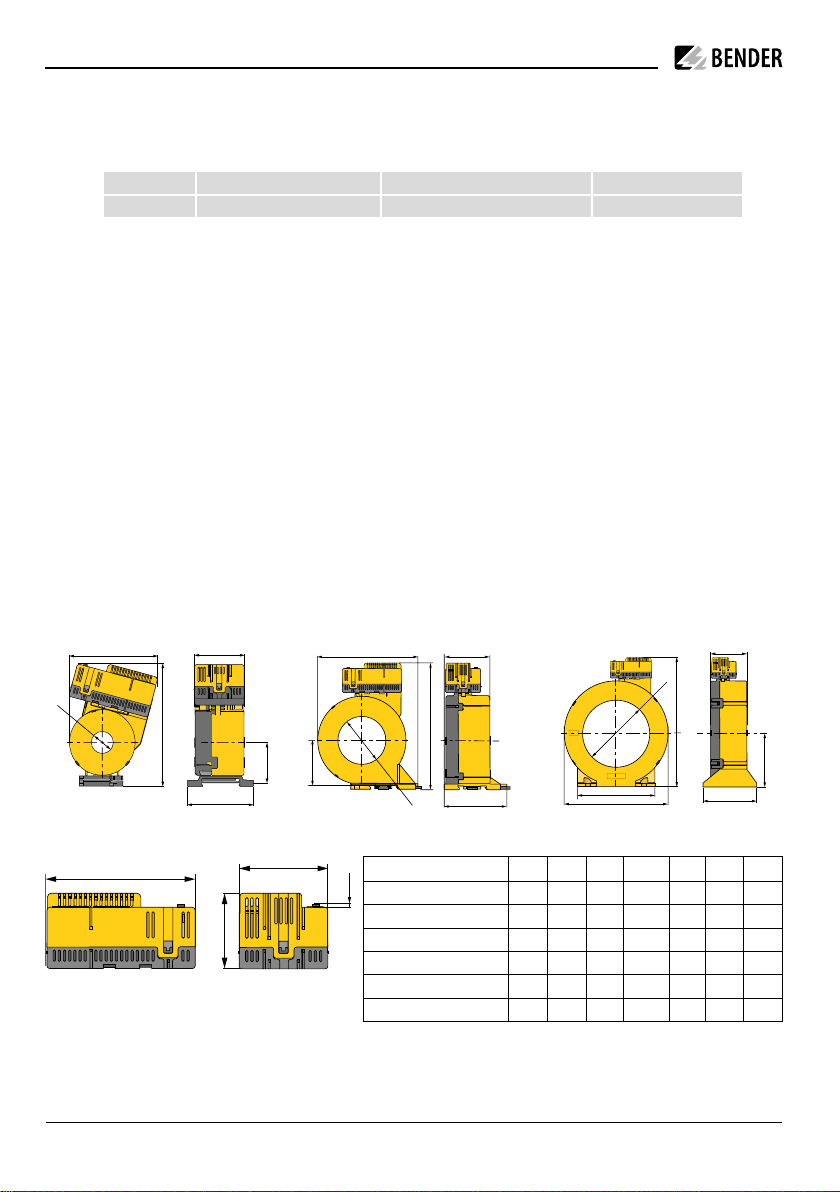
Dimension diagrams RCMB30... + CTBC... (all dimensions in mm, tolerance ±0.5 mm)
d
b
c
f
b
d
f
g
RCMB30… + CTBC20(P)/CTBC35(P) RCMB30… + CTBC60(P) RCMB30… + CTBC120(P)/CTBC210(P)
a
b
RCMB30…
2 RCMB300 series_D00372_01_Q_XXEN/06.2019
d
Type a b c d e f g
RCMB30…-CTBC20(P) 81 112 37 ø 20 46 60
RCMB30…-CTBC35(P) 97 130 47 ø 35 46 61
RCMB30…-CTBC60(P) 126 158 57 ø 60 56 78
RCMB30…-CTBC120(P) 188 232 96 ø 120 65 96 139
RCMB30…-CTBC210(P) 302 346 153 ø 210 67 113 277
RCMB30… 74 37 44 2 4.6
d
b
c
f
Page 3

Dimensions of mountings
34789
RCMB300 series
c
c
Type a b c
CTBC20(P) 31.4 49 2 x ø 5.5
CTBC35(P) 49.8 49 2 x ø 5.5
c
b
a
b
b
a
a
CTBC60(P) 56 66 2 x ø 6.5
CTBC120(P) 103 81 4 x ø 6.5
CTBC210(P) 180 98 4 x ø 5.5
CTBC20(P)/CTBC35(P) CTBC60(P) CTBC120(P)/CTBC210(P)
Assembly
A complete residual current monitoring module consists of the RCMB30… evaluation electronics
and a CTBC20(P)…210(P) series measuring current transformer core. If ordered separately, these
two components must be plugged together and calibrated during commissioning.
Step 1: Place the electronic module on the mark on the
measuring current transformer.
Step 2: Fold the electronic module down onto the
2
3
measuring current transformer.
Step 3: Slide the electronic module onto the plug
1
contacts of the measuring current transformer.
Device view RCMB30…
No. Terminal Meaning
125610
11 12
11 12
K1 K2
21 22 2411 12 14
13 14
1 24 V
2 GND
3 D1
4 DG
5 T/R
6 GND
7 A
8 B
9 X1
10 X2
11 11, 12, 14
12 21, 22, 24
13 –
14 –
Supply voltage U
S
Contact feedback
Connection external test/reset
RS-485 interface
Terminals for cable bridge for connection of the
integrated terminating resistor of the RS-485
interface
Relay K1 (prewarning)
Relay K2 (alarm)
LED: operation "ON" and "Alarm"
Test and reset button "T"
RCMB300 series_D00372_01_Q_XXEN/06.2019 3
Page 4

RCMB300 series
Connection
N
L
F 6 A
RCMB301-CTBC...
21
22 24
21
22 241112 14
3
Refer to the manual for further connection options.
Commissioning - Modbus RTU
24 V
GND
T/R
GND
DC 24 V
AC
DC
SPD
L1
L2
L3
N
The use of a type 2 surge protection de-
i
vice (SPD) is mandatory due to possible
impulse voltages and in order to comply
with normative requirements.
The surge protection device must be connected upstream of the power supply
unit on the supply side.
Features of the surge protection device:
– Nominal discharge current In (8/20 μs): 20 kA
– Response time: 25 ns
– Two-stage: 1 varistor + 1 spark gab
– Alternatively, the power supply unit must be
connected to a CAT II supply without a surge
protection device.
Within an interconnection of devices via
i
the RS-485 interface, the first and the last
device must each be provided with a terminating resistor.
This device-internal resistor can be connected by means of a wire jumper or a
DIP switch.
X1 X2
Wire jumper
RCMB30...
first device
120 Ω
COM465IP
last device
120 Ω
DIP switch
Address setting
Every RCMB3… has a factory-set Modbus address. The address is 1XX, where XX = the last two
i
digits of the serial number. Example: Serial number = 12345678 -> Modbus address = 178
The preset address can be changed via a COMTRAXX gateway, via Modbus or directly on the device.
The address can be changed on the device before installation and offset calibration. The electronic module must not be connected to the measuring current transformer during address setting.
Each address in the bus system may only be assigned once.
4 RCMB300 series_D00372_01_Q_XXEN/06.2019
Page 5

RCMB300 series
LED flashing modes
A
B
medium mode change
C
D
E
once confirmation
slowly error
quickly ready for address modification
very quickly address setting mode
Address modification procedure
Phase Action LED
1 Supply the electronic module with power
Flashes red briey (A, error: no measuring
current transformer)
Flashes red briey (A, error)
Flashes red at medium speed (B, mode
Press and hold "T" until the LED ashes red very quickly; release
2
afterwards
change)
Flashes red quickly (C, ready for address
setting mode)
3 Set address (address setting range: 1…247) Flashes red quickly (D, address setting mode)
Press "T" repeatedly until reaching the desired digit of the
units place
Units
3a
place
Acknowledge the entry: Press and hold "T" until the LED
ashes red; release afterwards
Press "T" repeatedly until reaching the desired digit of the
tens place
Tens
3b
place
Acknowledge the entry: Press and hold "T" until the LED
ashes red; release afterwards
Press "T" repeatedly until reaching the desired digit of the
Hundreds
3c
hundreds place
place
Acknowledge the entry: Press and hold "T" until the LED
ashes red; release afterwards
Check address setting: LED indicates the address by ashing
Each keystroke is conrmed with green (E)
Lights green shortly (E)
LED ashes red briey (C)
Each keystroke is conrmed with green (E)
Lights green shortly (E)
LED ashes red briey (C)
Each keystroke is conrmed with green (E)
Lights green shortly (E)
LED ashes red briey (C)
1)
Digit units place Flashes green for each number (E)
Pause o
4
Digit tens place Flashes green for each number (E)
Pause o
Digit hundreds place Flashes green for each number (E)
Pause o
5 Address set
1)
Example for "Check address setting": flashing pattern after successful setting of address "124" :
E
E
E
Flashes red briey (A, error: no measuring
current transformer)
A
RCMB300 series_D00372_01_Q_XXEN/06.2019 5
Page 6

RCMB300 series
System state LED and output relays
The LED indicates the system state by means of colours and lighting/flashing. The changeover
contacts of the relay outputs K1 and K2 have defined switching positions for each system state.
System state GREEN LED ONRED LED
Notes
Alarm
Device switched o o o Device is de- energised, no monitoring, no
monitoring function
Normal operating state lights o The device is supplied with the specied
voltage and monitors the primary circuit.
No residual current ows which would
lead to tripping.
Prewarning lights ashes
briey
The device is supplied with the specied
voltage and monitors the primary circuit.
A fault current ows which exceeds the
set limit of the prewarning.
Alarm state o lights The device is supplied with the specied
voltage and monitors the primary circuit.
A fault current ows which exceeds the
set limit of the alarm.
Device error o ashes
slowly
The device is supplied with the specied
voltage and monitors the primary circuit.
An error is detected by the periodic self
tests.
Device in calibration
see manual for DC calibration procedure
mode
Device in address mode see manual for procedure
Device signalling Flash quickly in alter-
nation
Modbus register 20006 = 2
Use to detect the device in its environment faster. Is automatically deactivated
after one minute.
Relay K1 Relay K2
de-energised de-energised
energised energised
de-energised energised
de-energised de-energised
de-energised de-energised
de-energised de-energised
6 RCMB300 series_D00372_01_Q_XXEN/06.2019
Page 7

Installation instructions measuring current transformer
PE
*
Do not route any shielded cables through the measuring current transformer.
i
CAUTION! Device damage due to high induction currents! High currents can be induced into
the conductor loop due to the AC/DC sensitive measuring technology used. Do not route pro-
I
tective conductors and low-resistance conductor loops through the measuring current transformer!
CAUTION! Device damage due to interference pulses! The connecting cable (supply, analogue
interface ...) must not be routed directly past the current transformer core.
I
CAUTION! Risk of injury due to accessible live conductors!
The measuring current transformer must be connected to the corresponding evaluator before
I
the first use and before commissioning of the monitored system.
L1
L2
L3
N
*
Never route an existing protective conductor through the measuring current trans-
All current-carrying cables must be routed together through the measuring current
transformer.
The primary conductors may only be bent from the specified minimum distance. The
minimum bending radius specified by the manufacturers must be observed. Distance
to 90° angle = 2 * external diameter
RCMB300 series
The cables must be centred in the measuring current transformer.
Offset calibration and completion of the installation
Before commissioning the system, it is recommended that an offset calibration be carried out on
the RCMB module at the installation site. Note that during the offset calibration the system is
switched off and no current flows through the measuring current transformer. For the CTBC120
and CTBC210 measuring current transformer cores, an offset calibration is mandatory. The offset
calibration procedure is described in the manual.
The installation should be completed with a functional test: Press the "T" button for 1.5…5 s.
RCMB300 series_D00372_01_Q_XXEN/06.2019 7
Page 8

Technical data
ø current
transformers
Type
Art. No.
CTBC20
B98120001
CTBC20P
B98120002
CTBC35
B98120003
CTBC35P
B98120004
CTBC60
B98120005
CTBC60P
B98120006
CTBC120
B98120007
CTBC120P
B98120020
CTBC210
B98120008
CTBC210P
B98120021
4
STEP-PS/1 AC/24 DC/0.5
B94053110
14
STEP-PS/1 AC/24 DC/1.75
B94053111
34
STEP-PS/1 AC/24 DC/4.2
B94053112
Rated voltage .................................................................... 800 V
Overvoltage category ............................................................... III
Nominal supply voltage U
Operating range U
Power consumption ........................................................≤ 2.5 W
...............................................DC 24 V
s
...........................................................±20 %
S
Measuring circuit
Characteristics according to IEC 62020 and IEC/TR 60755
............................................................... AC/DC sensitive, type B
Measuring range ..................................................... 5 mA…20 A
Response value I
......................................................30 mA…3 A
Δn
Prewarning .....................................................50 %…100 % IΔn
Rated current I
n
CTBC20 when IΔn = 30 mA ....................................................40 A
CTBC20 when I
= 300 mA ..................................................63 A
Δn
CTBC20P ................................................................................80 A
CTBC35 when I
CTBC35 when I
= 30 mA ....................................................80 A
Δn
= 300 mA ................................................125 A
Δn
CTBC35P ..............................................................................160 A
CTBC60 when I
CTBC60 when I
= 30 mA ..................................................160 A
Δn
= 300 mA ................................................250 A
Δn
CTBC60P ..............................................................................320 A
CTBC120 when I
CTBC120P when I
CTBC210 when I
CTBC210P when I
CTBC210P when I
= 100 mA ..............................................330 A
Δn
= 100 mA ............................................630 A
Δn
= 300 mA ..............................................630 A
Δn
= 100 mA ............................................630 A
Δn
= 300 mA ..........................................1000 A
Δn
Operating uncertainty ...................................................±17.5 %
Relative uncertainty ................................................... 0…-35 %
Outputs
Outputs .....................................................2 changeover contacts
Operating principle .................... N/C operation or N/O operation
Switching outputs (K1, K2) .........................................250 V, 5 A
Switching capacity .............................................. 1500 VA/144 W
Contact data acc. to IEC 60947-5-1
Rated operational voltage AC.................................. 250 V/250 V
Utilisation category ................................................ AC-13/AC-14
Rated operational current AC ..........................................5 A/3 A
Rated operational voltage DC ............................... 220/110/24 V
Utilisation category ..............................................................DC12
Rated operational current DC .....................................0.1/0.2/1 A
Minimum current ............................................... 10 mA at DC 5 V
Ordering details
Suitable measuring current transformer cores
20 mm
35 mm
60 mm
120 mm
210 mm
System components
max. connected
current transformers
Type Art. No.
Accessories
Type Art. No.
USB to RS-485 interface converter B95012045
Terminal set for RCMB module (spare part) B74043124
Alle Rechte vorbehalten.
Nachdruck und Vervielfältigung
nur mit Genehmigung des Herausgebers.
Bender GmbH & Co. KG
Postfach 1161 • 35301 Grünberg • Deutschland
Londorfer Str. 65 • 35305 Grünberg • Deutschland
Tel.: +49 6401 807-0 • Fax: +49 6401 807-259
E-Mail: info@bender.de • www.bender.de
All rights reserved.
Reprinting and duplicating
only with permission of the publisher.
Bender GmbH & Co. KG
P.O. Box 1161 • 35301 Grünberg • Germany
Londorfer Str. 65 • 35305 Grünberg • Germany
Tel.: +49 6401 807-0 • Fax: +49 6401 807-259
E-mail: info@bender.de • www.bender.de
RCMB300 series_D00372_01_Q_XXEN/06.2019 / pdf / © Bender GmbH & Co. KG, Germany – Subject to change! The specied standards take into account the edition valid until 06/2019 unless otherwise indicated.
 Loading...