

Page 1
Operating Manual
Power in electrical safety
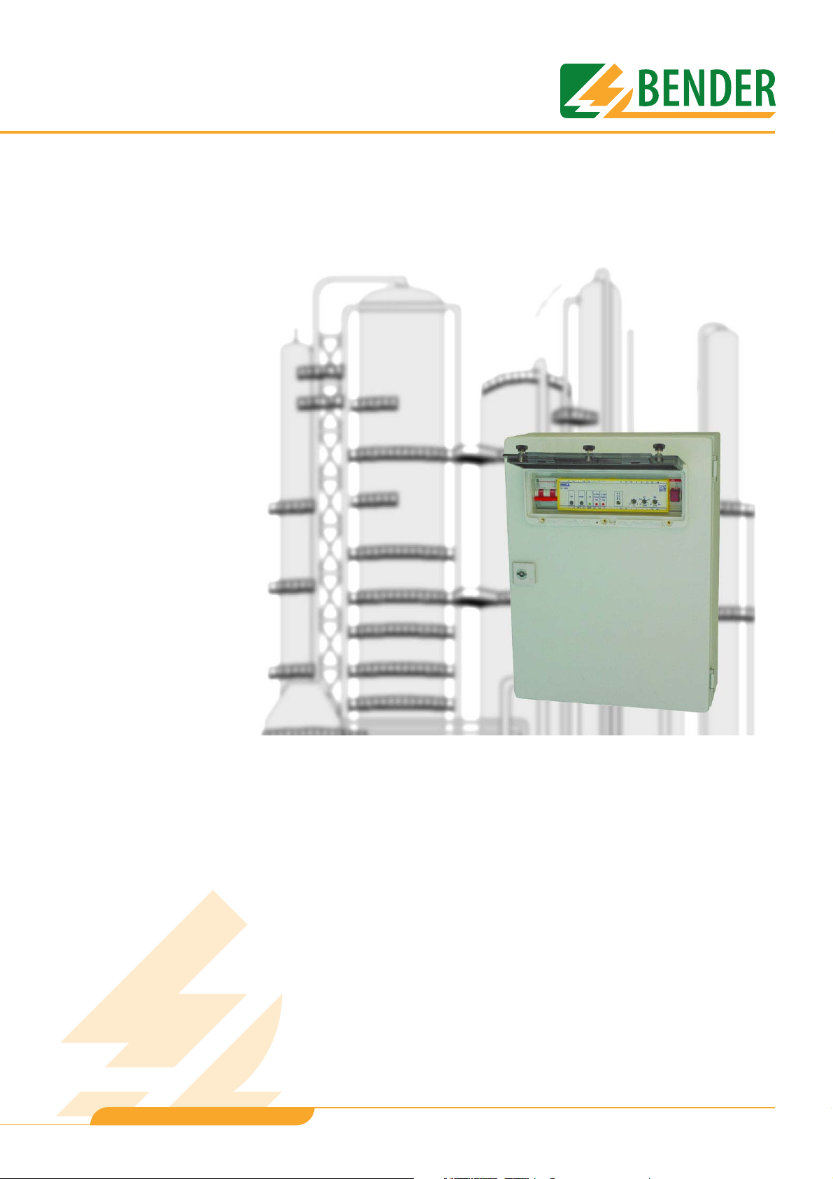
RC48N-70-10 A
RC48N-70-50 A
Ground-fault and neutral-grounding
monitoring system
TGH1397en/11.2006
Page 2

Dipl.-Ing. W. Bender GmbH & Co.KG
Londorfer Str. 65 • 35305 Grünberg • Germany
Postfach 1161 • 35301 Grünberg • Germany
Tel.: +49 (0)6401-807-0
Fax: +49 (0)6401-807-259
E-mail: info@bender-de.com
Web server: http://www.bender-de.com
© Dipl.-Ing. W. Bender GmbH & Co.KG
All rights reserved.
Reprinting only with permission
of the publisher.
Subject to change!
Page 3

Table of Contents
1. How to get the most out of this manual ............................................................. 5
1.1 How to use this manual ......................................................................................................... 5
1.2 Explanations of symbols and notes ................................................................................... 5
2. Safety instructions .................................................................................................. 7
2.1 Intended use .............................................................................................................................. 7
2.2 Qualified personnel ................................................................................................................. 7
2.3 General safety instruction ..................................................................................................... 7
2.4 Warranty and liability ............................................................................................................. 8
2.5 Guarantee ................................................................................................................................... 8
3. System description ................................................................................................. 9
3.1 Features ....................................................................................................................................... 9
3.1.1 Areas of application ................................................................................................................ 9
3.1.2 Description of function .......................................................................................................... 9
3.1.3 Mechanical design ................................................................................................................ 10
4. Installation and connection ............................................................................... 11
4.1 Installation ............................................................................................................................... 11
4.2 Connection .............................................................................................................................. 12
4.2.1 Connection diagram RC48N-70-10A .............................................................................. 12
4.2.2 Connection diagram RC48N-70-50A .............................................................................. 14
5. Operation and configuration ............................................................................. 17
5.1 Operating elements RC48N-70-10A ............................................................................... 17
5.2 Operating elements RC48N-70-50A ............................................................................... 18
5.3 Setting the alarm relay operating mode ...................................................................... 19
5.4 Factory settings ..................................................................................................................... 19
6. Data ......................................................................................................................... 21
6.1 Technical data ........................................................................................................................ 21
6.2 Applied standards ................................................................................................................. 22
6.3 Ordering details ..................................................................................................................... 22
TGH1397en/11.2006
3
Page 4

Table of Contents
4
TGH1397en/11.2006
Page 5
1. How to get the most out of this manual
1.1 How to use this manual
This operating manual describes how to operate the RC48N-70… ground-fault and neutralgrounding monitoring system, which is designed for use with high-resistance earthed installations. It is designed for skilled personnel working in the field of electrical engineering and
in particular for those designing, installing and operating electrical equipment.
Please read this operating manual and the enclosed sheet entitled "Important safety instructions for BENDER products" before using the equipment. This document must be kept in an
easily accessible location near to the equipment.
Should you have any questions, please do not hesitate to contact us. Please contact our Technical Sales Department. We are also happy to provide on-site service. Please contact our Service Department for more information.
Service hotline: 0700-BenderHelp (telephone and fax)
Carl-Benz-Straße 10 • 35305 Grünberg • Germany
Tel.: +49 (0) 64 01-807,760 • Fax: +49(0)64 01- 807 629
E-mail: info@bender-service.com • www.bender-de.com
Although great care has been taken in the drafting of this operating manual, it may nevertheless contain errors and mistakes. The BENDER Group cannot accept any liability for injury
to persons or damage to property resulting from errors or mistakes in this operating manual.
1.2 Explanations of symbols and notes
The following terms and symbols are used to denote hazards and instructions in
BENDER documentation:
This symbol indicates an immediate risk to life and limb.
Failure to observe the associated instructions and take appropriate precautions
will result in death, serious physical injury or substantial damage to property.
Danger !
This symbol indicates a potential risk to life and limb.
Failure to observe the associated instructions and take appropriate precautions
may result in death, serious physical injury or substantial damage to property.
Warning
This symbol indicates a potentially dangerous situation.
Failure to observe the associated instructions and take appropriate precautions
may result in minor physical injury or damage to property.
Caution
TGH1397en/11.2006
5
Page 6

How to get the most out of this manual
This symbol indicates important information about the correct use of the equipment purchased.
Failure to observe the associated instructions can result in equipment malfunctioning or cause problems in the environment in which it is being used.
This symbol indicates tips for using the equipment and particularly useful information. This type of information will help you to optimise your use of the equipment.
6
TGH1397en/11.2006
Page 7

2. Safety instructions
2.1 Intended use
The RC48N-70... ground-fault and neutral-grounding monitoring system is solely intended for
use with high-resistance earthed installations, where it is used to monitor the following:
● Residual current in the protective earth conductor
● Voltage between the transformer neutral and earth
● Neutral earthing resistor continuity (NER).
Please note the limits of the area of application indicated in the technical data. Use
deviating from or beyond the scope of this is considered non-compliant.
In order to comply with intended use, all instructions in this manual must be observed.
2.2 Qualified personnel
Only appropriately qualified personnel may work on BENDER products. Qualified
means personnel who are familiar with the assembly, first use and operation of the equipment and have undergone appropriate training. Such personnel must have read this manual
and understood all instructions relating to safety.
2.3 General safety instruction
BENDER equipment is designed and built in accordance with the state of the art and accepted rules in respect of technical safety. However, the use of such devices may introduce risks
to the life and limb of the user or third parties and/or result in damage to BENDER equipment or other property.
● Only use BENDER equipment:
–As intended
– If in perfect working order
– In accordance with the accident prevention regulations and guidelines applicable in the
location of use
● Rectify any faults that may endanger safety immediately.
● Do not make any unauthorised changes and only use replacement parts and optional accesso-
ries purchased from or recommended by the manufacturer of the equipment. Failure to
observe this requirement can result in fire, electric shock and injury.
● Reference plates must always be clearly legible. Replace damaged or illegible plates immedi-
ately.
TGH1397en/11.2006
7
Page 8

Safety instructions
2.4 Warranty and liability
In the event of physical injury or damage to property, no claims in respect of warranty or
liability can be accepted if such injury or damage can be attributed to one or more of the
following causes:
● Non-compliant use
● Incorrect assembly, commissioning, operation and maintenance.
● Operation of equipment with faulty safety devices or safety and protection devices which have
been fitted incorrectly or are not in perfect working order.
● Non-observance of instructions in this operating manual and the supplement entitled "Impor-
tant safety instructions for BENDER products" in respect of transport, storage, installation, commissioning, operation and maintenance.
● Constructional changes made by parties other than the manufacturer.
● Non-observance of technical data.
● Repairs carried out incorrectly and the use of replacement parts or accessories not approved by
the manufacturer.
● Catastrophes
● Uncontrollable external factors and force majeure.
2.5 Guarantee
BENDER provides a guarantee of error-free design and perfect material quality lasting 24
months from date of delivery for equipment stored or operated under standard conditions.
The guarantee does not cover maintenance work of any type. It is only valid for the first buyer and does not cover products or individual components used other than as intended or to
which changes have been made. Using the equipment other than as intended or under abnormal operating conditions will render any guarantee null and void.
The guarantee obligation is restricted to repairing or replacing equipment returned to BENDER within the guarantee period. In order for claims made under the terms of the guarantee
to be accepted, BENDER must acknowledge that the product is faulty and that the fault concerned cannot be attributed to the incorrect handling or modification of equipment, noncompliant use or abnormal operating conditions.
Any guarantee will be rendered null and void if repairs or cha nges have been made to equipment by persons other than those authorised to do so by BENDER. These guarantee provisions are valid exclusively and supersede all other contractual or legal warranty obligations,
including, but not restricted to, the legal warranty in respect of marketability, fitness for purpose and serviceability for a specific application. BENDER does not accept any liability for
direct and indirect collateral or consequential damage, regardless of whether this can be attributed to action considered permissible, impermissible or otherwise.
8
TGH1397en/11.2006
Page 9

3. System description
3.1 Features
3.1.1 Areas of application
Installations featuring high-resistance neutral-earthing are used whenever power supply failure would incur significant costs due to production downtimes (e.g. the automotive industry,
chemicals industry). With this type of installation, an insulation fault between a phase and
the earth will not result in failure of the power supply. However, the insulation fault must
be located and rectified as quickly as possible to avoid tripping the overcurrent protective
device as a result of an additional insulation fault in a second phase.
3.1.2 Description of function
In the case of high-resistance earthed installations, the maximum earth-fault current between
the transformer neutral and earth is limited by means of a neutral earthing resistor (NER).
The RC48N-70... ground-fault and neutral-grounding monitoring system monitors the status
of the NER and the earth-fault current flowing through this resistor.
The safe operation of the system can only be ensured if the maximum earth-fault current is
smaller than the trip current for the overcurrent protective device. In the event of a malfunction, the earth-fault current is detected by a W0-S15 measuring current transformer. If the set
response values and delay are exceeded, the RC48N-70... will signal an alarm. Alarm messages are indicated by means of the “ALARM Ground Fault” and “ALARM Resistor Fault” LEDs
on the RC48N as well as by the integrated H3 alarm lamp. There is also the option of connecting an external indicator (alarm annunciator panel). In this case, the H1 and H2 alarm
lamps signal the relevant alarm messages.
The alarm remains pending (i.e. is stored) until it is reset using the integrated RESET key.
The alarm relay can be used to trip a circuit-breaker. Depending on the type of circuit-breaker’s tripping coil, the operating mode can be set either to N/O operation or N/C operation.
TGH1397en/11.2006
9
Page 10

System description
3.1.3 Mechanical design
The RC48N-70... ground-fault and neutral-grounding monitoring system consists of a steel
plate housing containing the following built-in components. Assembly plan RC48N-70-10A:
1
2
3
4
5
6
ON
OFF
-X1
RC48N-935
W0-S15
ALARM
8
CD1000
9
W0-S15
10
13
14
7
11
12
1 Mounting plate: Used for mounting all the components directly or by means of DIN-
rails.
2 A transparent window ensures access to all operating elements even when the
housing door is closed.
3 Master switch S1: Monitoring ON/OFF
4 RC48N-935 ground-fault and neutral-grounding monitor
5 Housing door lock
6 Terminal strip for connecting the RC48N-70...
7
If necessary, additional terminals or relays can be mounted on the 35 x 7.5 mm DIN-rail.
8 In the event of an alarm, alarm lamp H3 will light up
9 Coupling device CD1000 enables the voltage to be measured between the trans-
former neutral and earth up to a maximum of 1000 V AC.
10 Measuring current transformer W0-S15 to detect the current flowing through the
NER. The RC48N-70-50A features two measuring current transformers. The second
measuring current transformer generates a measurement signal reduced by a factor of 100. As a result, currents of up to 100 A can be detected with the RC48N-7050A.
11 Earthing terminal M6
12 Cone cable glands M20 for connecting cables
13 Housing door (right-hand stop)
14 Transparent trap window. To open, loosen knurled screws.
10
TGH1397en/11.2006
Page 11

4. Installation and connection
Before mounting the device and working on the device connections, make sure
that the voltage has been disconnected. Failure to comply with this requirement
will expose personnel to the risk of electric shock.
Danger !
4.1 Installation
Install the RC48N-70... ground-fault and neutral-grounding monitoring system using four
screws (
Outline drawing
Furthermore, the electrical installation may sustain damage and the device be
destroyed beyond repair.
∅ max. 8 mm, see outline drawing).
234
98 32
400
F 8,7
20 200
20
20
50 3535603535
Dimensions in mm
300
20
360
6 x M20
46
120
TGH1397en/11.2006
11
Page 12

4.2 Connection
4.2.1 Connection diagram RC48N-70-10A
U1
Installation and connection
Alarm
GFA or NRA
H3
K11 14 21 LA1
12 22 24
A2
A2A1
RC48N-935
ALARM GFA or NRA
Alarm
Betrieb
t=0,1-2s I n=0,1-1A U =20-400V
Resistor
Fault
Ground
Fault
Reset
Test
Output
DC12 V
NC NC
G
G1
U-
U+R
GFA NRA C1 C2
T
PE
Uh
DC110 V
+
-
82
NRA
GFA
L-
: DC 110 V
: 7 W
L+
s
1 9 345T1 N1 6 7
S
U
P
Alarm Annunciator Panel
H1 H2
12
S1
RC48N-70-10A
-T2
600/1
U2
N
G1
G
CD1000
Tr. 6.6 kV / 0.4 kV
3 phase 50 Hz
L1L2L3
PE
PE
-X1
NER
TGH1397en/11.2006
Page 13

Installation and connection
Key for connection diagram RC48N-70-10A
Devices
U1 RC48N-935 ground-fault and neutral-grounding monitor
U2 Coupling device CD1000 enables the voltage to be measured between the trans-
-T2 Measuring current transformer W0-S15 to detect the current flowing through the
NER Neutral earthing resistor.
S1 Master switch monitoring ON/OFF
H3 In the event of an alarm, alarm lamp H3 will light up
H1, H2 Optional, external indicator (alarm annunciator panel) with alarm lamps
-X1 Connection terminals
former neutral and earth up to a maximum of 1000 V AC.
NER.
H1 “ALARM Ground Fault” (GFA) and H2 “ALARM Resistor Fault” (NRA).
T1, N1 rigid 2.5 ... 25 mm
2
flexible 4 ... 16 mm2
1 x PE rigid 0.5 ... 16 mm
flexible 0.5 ... 10 mm
2 x PE rigid 0.2 ... 6 mm
1 ... 9 flexible 0.2 ... 4 mm
2
2
2
2
Connections
T1 Connection to transformer star point
N1 Connection to NER (neutral earthing resistor)
PE Connections to PE (protective earth)
1, 2 Connection of supply voltage U
= 110 V DC
s
Recommended fuse: 6 A fuse as short-circuit protection for supply voltage
6 Connection of external alarm lamp GFA (H1). H1 lights up if the residual current
response value and the response time are exceeded.
7 Connection of external alarm lamp NRA (H2). H2 lights up if the voltage across the
neutral earthing resistor exceeds the response value or if the NER’s resistance
exceeds 2 KΩ.
8, 9 Connection of external auxiliary supply (e.g. 110 V DC) for external alarm lamps
3, 4, 5 Alarm relays (free changeover contacts) trip in the event of an alarm. Alarm relay
can be used to trigger an acoustic signal or switching operation. Set using NC-NC
bridge, either N/C or N/O operation can be selected.
TGH1397en/11.2006
13
Page 14

4.2.2 Connection diagram RC48N-70-50A
U1
345
Alarm
Installation and connection
GFA or NRA
H3
K11 14 21 LA1
12 22 24
A2
A2A1
RC48N-935
ALARM GFA or NRA
Alarm
Betrieb
Faktor =100
t=0,1-2s I n=0,1-1A U =20-400V
Resistor
Fault
Ground
Fault
Reset
Test
Output
DC12 V
NC NC
G
G1
U-
U+R
GFA NRA C1 C2
T
PE
Uh
DC110 V
+
-
967 8
Alarm Annunciator Panel
GFA NRA
H1 H2
L-
2
1
L+
: DC 110 V
s
U
: 7 W
S
P
14
-T3
600/1
Man. n=6
S1
RC48N-70-50A
Wrapping
-T2600/1
U2
N
G1
G
CD1000
Tr. 33 kV / 6.9 kV
3 phase, 50 Hz
L1L2L3
PE
PE
T1 N1
-X1
T1
4 kV /0.4 kV
20 kVA
NER
TGH1397en/11.2006
Page 15

Installation and connection
Key for connection diagram RC48N-70-50A
Devices
U1 RC48N-935 ground-fault and neutral-grounding monitor
U2 Coupling device CD1000 enables the voltage to be measured between the trans-
-T2, -T3 Measuring current transformer W0-S15 to detect the current flowing through the
NER Neutral earthing resistor.
S1 Master switch monitoring ON/OFF
H3 In the event of an alarm, alarm lamp H3 will light up
H1, H2 Optional, external indicator (alarm annunciator panel) with alarm lamps
-X1 Connection terminals
former neutral and earth up to a maximum of 1000 V AC.
NER.
H1 “ALARM Ground Fault” (GFA) and H2 “ALARM Resistor Fault” (NRA).
T1, N1 rigid 2.5 ... 25 mm
2
flexible 4 ... 16 mm2
1 x PE rigid 0.5 ... 16 mm
flexible 0.5 ... 10 mm
2 x PE rigid 0.2 ... 6 mm
1 ... 9 flexible 0.2 ... 4 mm
2
2
2
2
Connections
T1 Connection to transformer star point
N1 Connection to NER (neutral earthing resistor)
PE Connections to PE (protective earth)
1, 2 Connection of supply voltage U
= 110 V DC
s
Recommended fuse: 6 A fuse as short-circuit protection for supply voltage
6 Connection of external alarm lamp GFA (H1). H1 lights up if the residual current
response value and the response time are exceeded.
7 Connection of external alarm lamp NRA (H2). H2 lights up if the voltage across the
neutral earthing resistor exceeds the response value or if the NER’s resistance
exceeds 2 KΩ.
8, 9 Connection of external auxiliary supply (e.g. 110 V DC) for external alarm lamps
3, 4, 5 Alarm relays (free changeover contacts) trip in the event of an alarm. Alarm relay
can be used to trigger an acoustic signal or switching operation. Set using NC-NC
bridge, either N/C or N/O operation can be selected.
TGH1397en/11.2006
15
Page 16

Installation and connection
16
TGH1397en/11.2006
Page 17

5. Operation and configuration
5.1 Operating elements RC48N-70-10A
S1 H3U1
ON
OFF
RC48N
A1 A1
TEST
RESET
T R NRA C2 U+ G1 G k l NC NC
GFA C1 U-
A2
ALARM
Ground
ON
Fault
ALARM
Resistor
Fault
A2
11 12 14
Filter off / on
IDn x 10 / x 1
0,1
1
t / s
0,5
0,1
2
I
D
22 24
21
IDn
W
MONITOR
200
1
20
n /A
UD / V
ALARM
VD
400
12 7654398
10 11 12
1Master switch S1: Monitoring ON/OFF
2 Press the TEST key to initiate the following sequence: A test residual current is simulated and
once the response time has elapsed, an alarm is recognised; which causes the alarm relay to
switch and the “ALARM Ground Fault” LED and alarm lamp H3 to light up. The alarm message is
stored.
3 Press the RESET key to delete alarm messages
4 ON LED (green) lights up to indicate that the RC48N is in operation.
5 The “ALARM Ground Fault” LED (red) lights up if the residual current response value and the
response time are exceeded.
6 The “ALARM Resistor Fault” LED (red) lights up if the voltage across the neutral earthing resistor
exceeds the response value or if the NER’s resistance exceeds 2 KΩ..
7 DIP switch “Filter OFF/ON”: Bandpass filter 50 ... 60 Hz.
When the bandpass filter is switched on, only the narrow-band 50 ... 60 Hz components of the
residual current are detected. This function can be used to prevent erroneous tripping as a
result of harmonics and transient components in the residual current.
8DIP switch “IΔn x 10 / x 1”: For configuring the setting range of the residual current response
value IΔ n/A
x 1: 0.1 A ... 1 A
x 10: 1 A ... 10 A
9 For setting the response delay t/s for the residual current measurement from 0.1 to 2 seconds.
For setting the residual current response value from 0.1 A to 1 A and 1 A to 10 A respectively.
10
11 For setting the response value for voltages across the neutral earthing resistor from
20 to 400 V.
12 In the event of an alarm, alarm lamp H3 will light up.
TGH1397en/11.2006
17
Page 18

5.2 Operating elements RC48N-70-50A
S1 H3U1
A1 A1
A2
A2
ON
RC48N
ALARM
ALARM
Resistor
Ground
ON
Fault
Fault
OFF
TEST
RESET
T R NRA C2 U+ G1 G k l NC NC
GFA C1 U-
11 12 14
Filter off / on
IDn x 10 / x 1
0,1
Operation and configuration
22 24
21
IDn
W
x100
1
t / s
0,5
0,1
2
D
n /A
I
MONITOR
200
1
20
UD / V
ALARM
VD
400
12 7654398
10 11 12
1 Master switch S1: Monitoring ON/OFF
2 Press the TEST key to initiate the following sequence: A test residual current is simulated and
once the response time has elapsed, an alarm is recognised; which causes the alarm relay to
switch and the “ALARM Ground Fault” LED and alarm lamp H3 to light up. The alarm message is
stored.
3 Press the RESET key to delete alarm messages
4 ON LED (green) lights up to indicate that the RC48N is in operation.
5 The “ALARM Ground Fault” LED (red) lights up if the residual current response value and the
response time are exceeded.
6 The “ALARM Resistor Fault” LED (red) lights up if the voltage across the neutral earthing resistor
exceeds the response value or if the NER’s resistance exceeds 2 KΩ.
7 DIP switch “Filter OFF/ON”: Bandpass filter 50 ... 60 Hz.
When the bandpass filter is switched on, only the narrow-band 50 ... 60 Hz components of the
residual current are detected. This function can be used to prevent erroneous tripping as a
result of harmonics and transient components in the residual current.
8 The second measuring current transformer generates a measurement signal reduced by a fac-
tor of 100. Set this DIP switch to x1. The response value set at the potentiometer (0.1... 1 A) is
multiplied by the factor x100.The response range is 10 A ... 100 A.
9 For setting the response delay t/s for the residual current measurement from 0.1 to 2 seconds.
10 For setting the residual current response value from 10 A to 100 A. Example: On the device,
select 0.1 A for an actual response value of 10 A.
11 For setting the response value for voltages across the neutral earthing resistor from
20 to 400 V.
12 In the event of an alarm, alarm lamp H3 will light up.
18
TGH1397en/11.2006
Page 19

5.3 Setting the alarm relay operating mode
You can set the operating mode for the alarm relay via a bridge between the NC-NC contacts
on the RC48N-935:
A2A1
RC48N-935
GFA NRA C1 C2
12 22 24
U+R
U-
Bridge open N/O operation
Bridge closed N/C operation (factory setting)
5.4 Factory settings
RC48N-70-10A RC48N-70-50A
Filter:
DIP switch “Filter off / on”
on on
K11 14 21 LA1TA2
G1
NC NC
G
Response range:
x10 => 1...10 A x1 => 0.1...1 A
DIP switch “IΔn x 10 / x 1”
Response delay t/s for alarm IΔn 0.1 s (left-hand stop) 0.1 s (left-hand stop)
Residual current response value IΔn/A 0.1 A (left-hand stop) 0.1 A (left-hand stop)
x factor 100 => 10 A
Response value for voltage drop UΔ/V at
20 V (left-hand stop) 20 V (left-hand stop)
the neutral earthing resistor NER
Operating principle of alarm relay:
closed (N/C operation) closed (N/C operation)
NC-NC bridge
Response value for interruption of the neu-
> 2 kΩ > 2 kΩ
tral earthing resistor (permanent setting)
Response delay for interruption of NER and
5 s 5 s
voltage drop at the NER
(permanent setting)
TGH1397en/11.2006
19
Page 20

Operation and configuration
20
TGH1397en/11.2006
Page 21

Data
6. Data
6.1 Technical data
Insulation coordination acc. to IEC 60664-1
Rated insulation voltage........................................................................................................................................ AC 250 V
Rated impulse withstand voltage/contamination level........................................................................................ 2.5 kV/3
Voltage ranges
Supply voltage U
Fuse....................................................................................................................................... recommended: 6 A slow fuse
Power consumption ................................................................................................................... approx. 5.8 VA at AC 60 V
.................................................................................................................................................. approx. 8.5 VA at AC 264 V
Residual current monitoring
Response value, residual current ................................................... RC48N-70-10A: adjustable 0.1 ... 1 A resp. 1 ... 10 A
................................................................................... RC48N-70-50A: adjustable 10 ... 100 A (Scale value x Factor 100)
Accuracy..........................................................................................................................................................+ 0 ... - 25 %
Response delay .................................................................................................................................... adjustable 0.1 ... 2 s
Accuracy of response delay.................................................................................................................................. ± 20 %
Continuous short circuit current..................................................................................................................................200 A
........................................................................................................................................................................2500 A for 2 s
Operating mode ...................................................................................................................................................... latching
..............................................................................................................AC/DC 60 ... 264 V, 50 ... 60 Hz,
S
Neutral earthing resistor monitoring
Response value, voltage measurement........................................................................................... adjustable 20 ... 400 V
Accuracy............................................................................................................................................................... ± 10 %
Response value, neutral grounding resistor at U
Accuracy..........................................................................................................+ 5 ... - 2 % of the coupling resistance
Response time ..................................................................................................................................................5 s ± 20 %
Operating mode ...................................................................................................................................................... latching
Outputs
Switching elements (alarm relay) .................................................................................................... 1 changeover contact
Rated contact voltage ........................................................................................................................ AC 250 V / DC 300 V
Limited making capacity .................................................................................................................................... AC/DC 5 A
Limited breaking capacity AC/DC ......................................................................................................................... 2/0.2 A
Permissible number of operations ................................................................................................................. 12000 cycles
Operating mode, alarm relay, selectable (bridge)........................................................... N/O operation / N/C operation
Switching elements (GFA, NRA) .................................................................................................................... 2 NO contacts
Rated contact voltage ........................................................................................................................ AC 250 V / DC 300 V
Limited making capacity..................................................................................................................................... AC/DC 5 A
Limited breaking capacity AC/DC ......................................................................................................................... 2/0.2 A
Permissible number of operations ................................................................................................................. 12000 cycles
Type tests
Test of the electromagnetic compatibility (EMC)
Immunity .........................................................................................................................................according to IEC 62020
Emissions ........................................................................................................................................ according to EN 50081
Emissions according to EN 55011/CISPR11 ........................................................................................................... Class A
= 0 V.......................................................................................... 2 k Ω
N
TGH1397en/11.2006
21
Page 22

General data
Operating temperature ................................................................................................- 40 °C ...+ 60 °C (233 K ... 333 K)
Storage temperature......................................................................................................- 55 °C ... + 80 °C (218 ... 353 K)
Climatic class according to IEC 60721 .......................................................................................................................... 3K5
Operating mode .................................................................................................................................continuous operation
Mounting.................................................................................................................................................... upright position
Connection ..................................................................................................................................................screw terminals
Protection class according to DIN EN 60529
Built-in components .................................................................................................................................................... IP 30
Housing/Window with knurled head screws ............................................................................................................. IP 66
Flammability class.................................................................................................................................................. UL94V-0
Colour of the housing............................................................................................................................................ RAL 7035
Dimensions (W x H x D).......................................................................................................................300 x 400 x 120mm
Weight............................................................................................................................................................. approx. 9 Kg
6.2 Applied standards
– CSA M421-00: Juli 2000: Use of electricity in mines
– AS 2081.1 - AS2081.5: Electrical equipment for Coal and Shale Mines
– IEC 62020:1998-08: Residual Current Monitors
Data
6.3 Ordering details
Type Designation Art. No.
RC48N-70-10A ground-fault and neutral-grounding monitoring system B 9401 3010
RC48N-70-50A ground-fault and neutral-grounding monitoring system B 9401 3011
22
TGH1397en/11.2006
Page 23

INDEX
Symbols
“ALARM Ground Fault” LED
, 18
17
“ALARM Resistor Fault” LED
, 18
17
A
Alarm lamp H3 17, 18
Alarm relay
Alarm relay operating mode
Areas of application
13, 15
9
B
Bridge 19
C
cable glands 10
D
Dimensions 11
DIP switch
17
19
Intended use
7
M
Measuring current transformer
10
N
NER 9
Neutral earthing resistor (NER)
13, 15
P
personnel 7
R
RESET key 17, 18
Response value
17, 18
S
Screws 11
Steel plate housing
10
E
Earth-fault current 9
F
Factor 100 10
G
Guarantee 8
H
Housing door 10
I
Installations
- High-resistance earthed
Insulation fault
TGH1397en/11.2006
9
5
T
Terminal strip 10
TEST key
Transparent window
Trip current
17, 18
9
10
23
Page 24

INDEX
24
TGH1397en/11.2006
Page 25

Page 26

Dipl.-Ing. W. Bender GmbH & Co.KG
Londorfer Str. 65 • 35305 Grünberg • Germany
Postfach 1161 • 35301 Grünberg • Germany
Tel.: +49 (0)6401-807-0
Fax: +49 (0)6401-807-259
E-Mail: info@bender-de.com
Web server: http://www.bender-de.com
 Loading...