

Bender PEM353 Quick Start Manual
DANGER
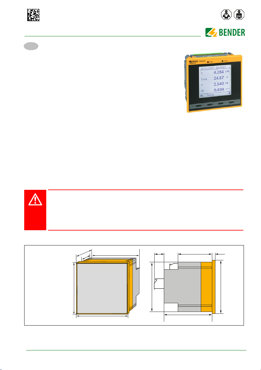
Dimensions in mm
Quick-start guide
PEM353
EN
Universal measuring device
This quick-start guide does not replace the operating manual. The
manual is available in the download area of our homepage
(https://www.bender.de/en/service-support/downloads).
Make sure that the personnel has read the operating manual and understood all instructions relating to safety.
Scope of delivery
1 x PEM353, 1 x rubber seal, 4 x retaining clips, 1 x safety instructions
for Bender products (multilingual), 1 x quick-start guide
Intended use
The PEM353 is suitable for use in 2-, 3- and 4-wire systems and in their respective versions as TN, TT and IT
systems. The current measurement inputs of the PEM353 are always connected via external …/1A or …/5A
measuring current transformers. In principle, measurements in medium and high-voltage systems are carried out via voltage transformers.
Use for the intended purpose also includes:
Device-specific settings compliant with local equipment and operating conditions
Adhering to the manual
Any other use than that described in this manual is regarded as improper.
Safety instructions
Risk of fatal injury due to electric shock!
Touching live parts of the system carries the risk of an electric shock, damage to the electrical installation
or destruction of the device.
Before installing and connecting the device, make sure that the installation has been de-energised.
Observe the rules for working on electrical installations.
Refer to the rated and supply voltage values as specified in the technical data!
Installation
PEM353_D00335_00_Q_XXEN/06.2018
67
47.3
96
91.5
96
13.2 47.3
91.5
67
7
96
1
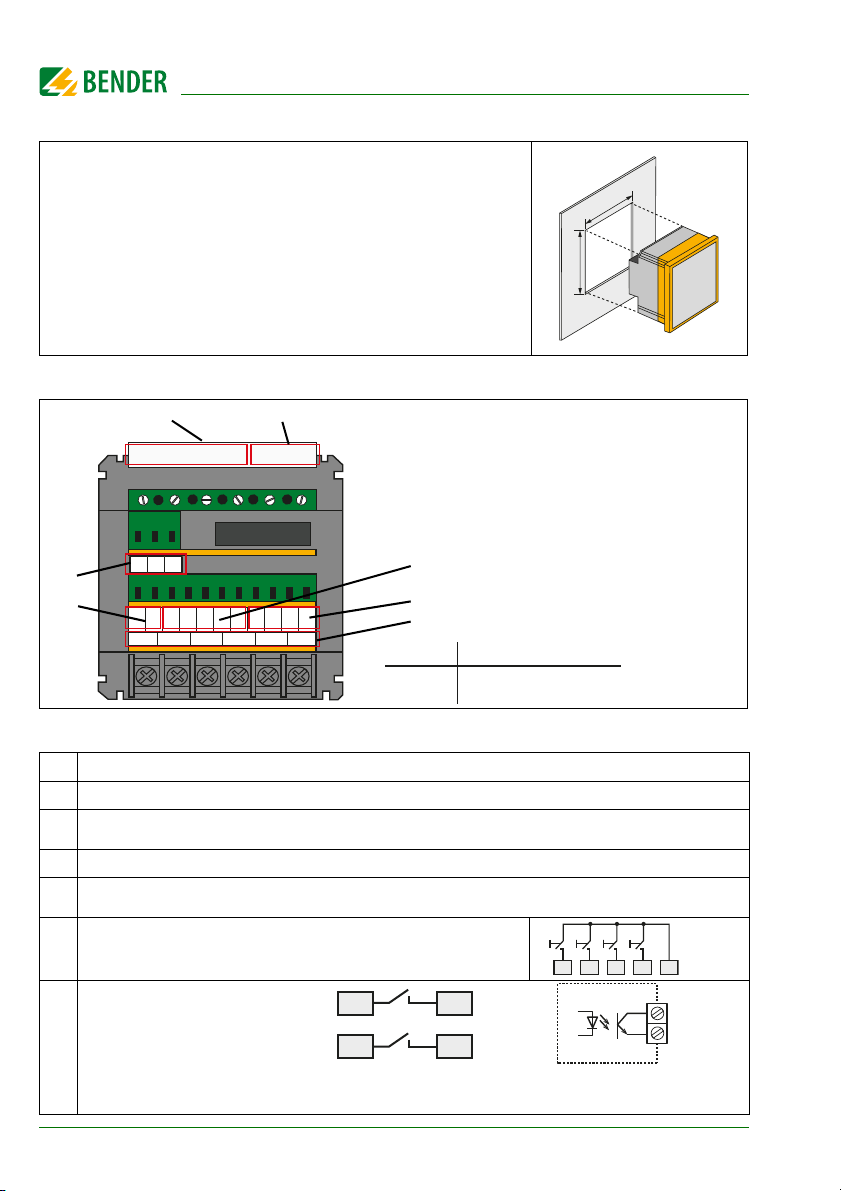
Mounting in a front panel
92
92
• l11 l12 l22
l32
• l21 • l31
L1 L2 L3 N A1/+ A2/–
D+ D– DIC DI4DI3DI2DI
1
DOaDObDOdDO
c
• l41
NC I42
DO
a
DO
b
DO
d
DO
c
PEM353(-N)
DO13 DO14 DO23 DO24
E1+
E1-
E2+
E2-
PEM353-P
1
2
6
7
5
4
3
Overview of the terminals:
The connections are located on
the back of the device
DO13 DO14
DO23 DO24
DO
E1+/E2+
E1- /E2-
PEM353-P features 2 pulse
outputs ("Solid State Relay")
PEM353(-N) features 2 configurable
outputs (N/O relay)
Digital outputs
Mounting opening 92 mm x 92 mm (max. 92.8 x 92.8 mm).
1. Mount the rubber seal on the back of the device.
2. Insert the device into the mounting opening of the front panel.
3. Place the four retaining clips over the device corners from behind.
4. Push the retaining clips tightly against the front plate.
5. Check the device to ensure that it is firmly installed.
The device is installed.
Connection
Legend
No. Connections
1 Measuring voltage inputs: The measuring leads should be protected with 2 A fuses.
Supply voltage: Power protection by a 6 A fuse, quick response.
2
If being supplied from an IT system, both lines have to be protected by a fuse.
(PEM353-N only)
4
of 1 mA is
min
DI1 DICDI2 DI3 DI4
Measuring current inputs I
3
RS-485 bus connection; Up to 32 devices can be connected to the bus.
4
The maximum cable length for the bus connection of all devices is 1200 m.
4 Digital inputs, galvanically isolated, 24 V;
An external circuit providing at least a current I
5
required for triggering the inputs.
6
2
PEM353_D00335_00_Q_XXEN/06.2018
 Loading...