

Page 1
1
Quickstart
Neutral Grounding Resistor Monitor
Intended use
The NGRM700 is only intended for use in high-resistance earthed systems. In these systems, the NGRM700 monitors
the current through the NGR,
the voltage between the star point of the transformer and earth
(voltage drop across the NGR),
the condition of the neutral grounding resistor (NGR),
line-to-line and line-to-earth voltages.
This quick-start guide does not replace the operating manual of the device.
Download: www.bender.de/manuals
Safety instructions
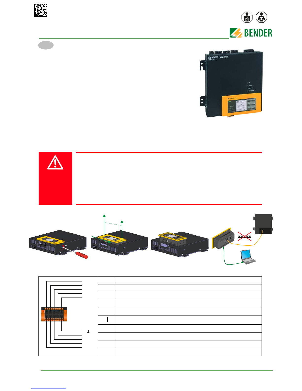
Removing FP200-NGRM
Connection X1
Risk of electrocution due to electric shock!
Touching live parts of the system carries the risk of:
An electric shock
Damage to the electrical installation
Destruction of the device
Before installing and connecting the device, make sure that the installation has
been de-energised. Observe the rules for working on electrical installations.
I1 Pulser IN
I2 Reset IN
I3 Test IN
A Modbus RTU (A)
B Modbus RTU (B)
Ground
M+ Analogue output
Q2 Open Collector: Pulser OUT
Q1 Open Collector: System health
+ Output for supply of external relays (+24 V, max. 100 mA)
DANGER
PH 1
X1 ETH
R
OFFON
1
2
X1
ETH
R
max. 5 m
Switch
RJ45:
Remote
RJ45:
Ethernet
I1
I2
I3
A
B
M+
Q2
Q1
+
NGRM700
NGRM700_D00292_02_Q_XXEN/06.2018
EN
Page 2
2
NGRM700_D00292_02_Q_XXEN/06.2018
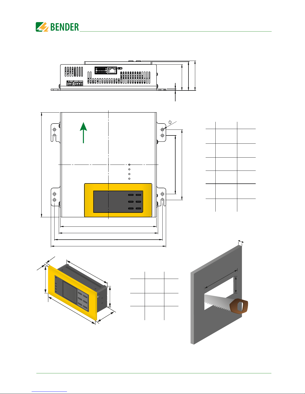
Dimension diagrams basic enclosure and FP200-NGRM
a
k
j
i
hgf
e
d
cb
l
3
55.50
61.40
63.35
150
125
230
245
205
223.50
211
a
k
j
i
h
g
f
e
d
c
b
l
0.12
2.19
2.42
2.49
5.91
4.92
9.06
9.65
8.07
8.80
8.31
mm in
6 0.236
Mounting position
top
a
f
e
d
c
b
a
f
e
d
c
b
mm in
135.5
65.5
35.6
144
72
5.8
5.33
2.58
1.40
5.67
2.38
0.23
5.43+0.02/-0
in
138+0.5/-0 mm
2.60+0.02/-0 in*
66+0.5/-0 mm*
max. 5.3 mm
* IP 65:
68+0.7/-0 mm
2.68+0.03/-0 in
max. 0.21 in
Page 3
3
NGRM700_D00292_02_Q_XXEN/06.2018
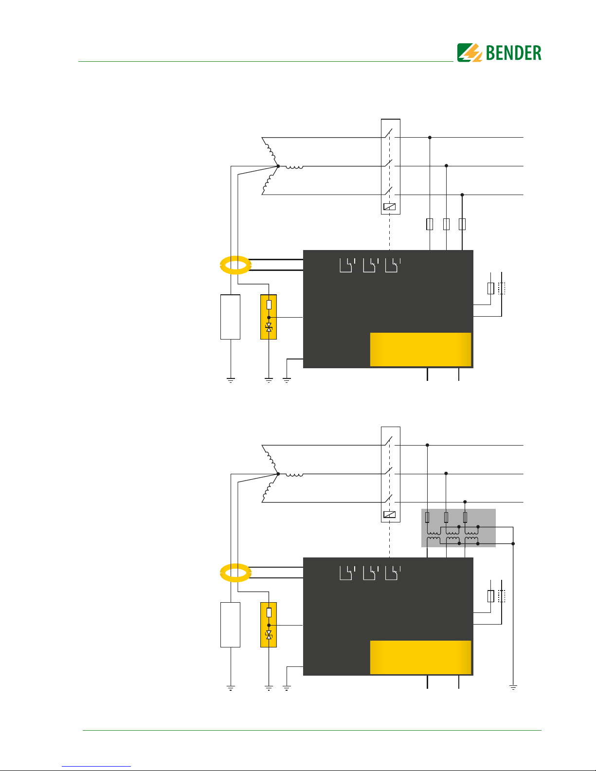
Connection ≤ 690 V
Connection > 690 V
k
l
AC/DC
24...240 V
6 A6 A
A1
A2
L1 L2 L3
R
S
E
C
50mA
5A
NGR
NGRM700
CT
Rs (G1)
E (G)
N
CD...
31 32 3421 22 24
11 12 14
FP200-NGRM
X1
Dig. IN/OUT Ethernet
6 A6 A6 A
L1
L2
L3
NGR
fault
Ground
fault
Trip
Circuit breaker
The "N" connection of the
CD-series coupling device
should be as close to the
transformer star point as
possible.
k
l
AC/DC
24...240 V
6 A6 A
A1
A2
L1 L2 L3
R
S
E
C
50mA
5A
NGR
NGRM700
CT
Rs (G1)
E (G)
N
CD...
31 32 3421 22 24
11 12 14
FP200-NGRM
X1
Dig. IN/OUT Ethernet
PT *
L1
L2
L3
NGR
fault
Ground
fault
Trip
Circuit breaker
* The PT ratio can be
selected on the NGRM700
The "N" connection of the
CD-series coupling device
should be as close to the
transformer star point as
possible.
Page 4
4
NGRM700_D00292_02_Q_XXEN/06.2018
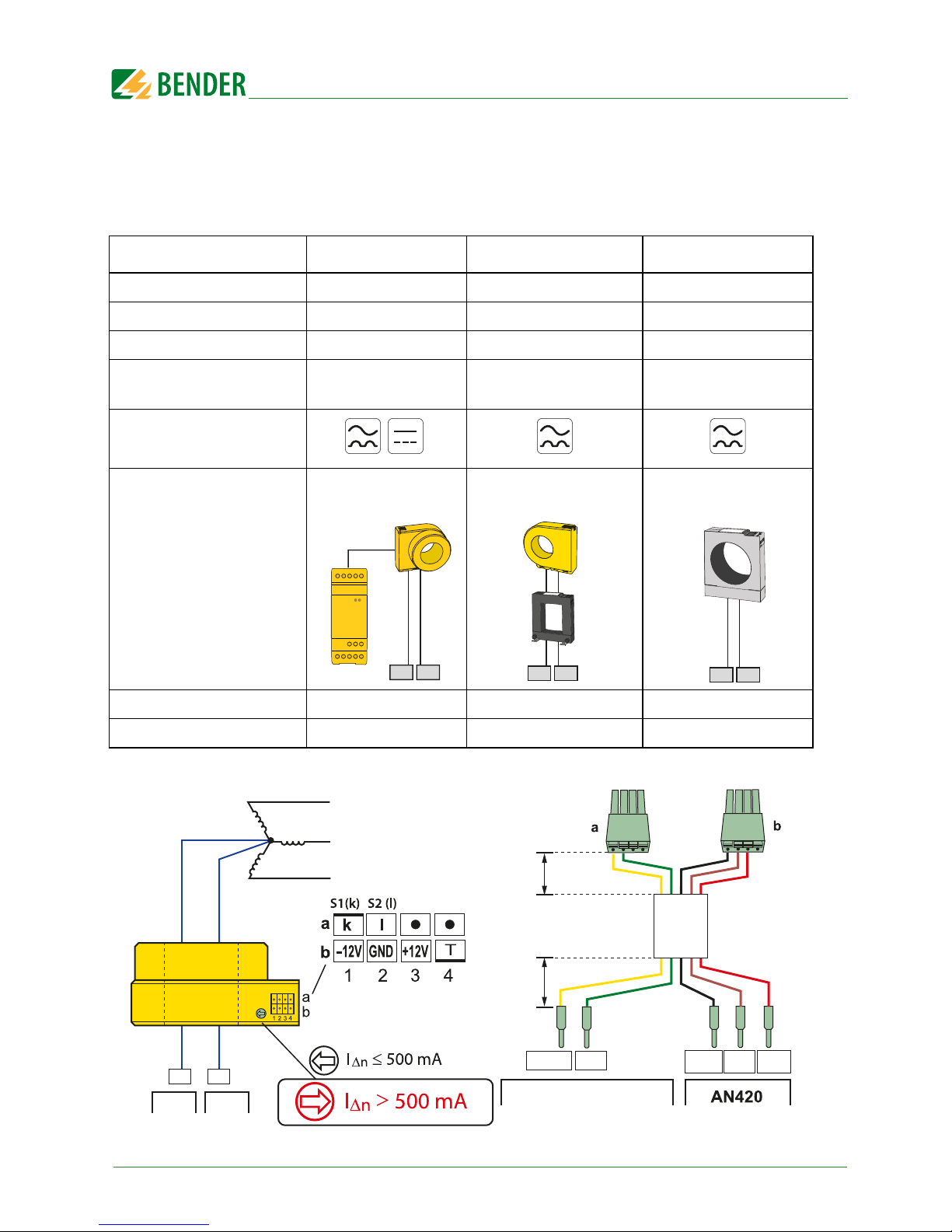
Measuring current transformer connection
Depending on the system to be monitored, a suitable measuring current transformer has to be chosen.
All common measuring current transformers (50 mA or 5 A on the secondary side) can be used. The following table helps you with the choice:
CT installation W…AB
System type AC + DC AC AC
I 1…10 A 5…25 A 5…25 A
f 0…3800 Hz 42…3800 Hz 50/60 Hz
Ratio 600:1 600:1 60:5
Length
connecting cables
max. 10 m max. 40 m
max. 25 m (4 mm²)
max. 40 m (6 mm²)
I
Δn
Typ e
W35…120AB W20…120
W1-S35…W5-S210
CTB31…41
CT: k NGRM700: 50 mA NGRM700: 50 mA NGRM700: 5 A
CT: l NGRM700: C NGRM700: C NGRM700: C
k
l
W...AB
AN420
k
l
W...
W...S...
k
l
CTB
NGRM700
C
50mA
lk
50 mm
1.97 in
250 mm
9.84 in
+12VGND–12V
WXS...
NGR CD...
N N
W...AB
Page 5
5
NGRM700_D00292_02_Q_XXEN/06.2018
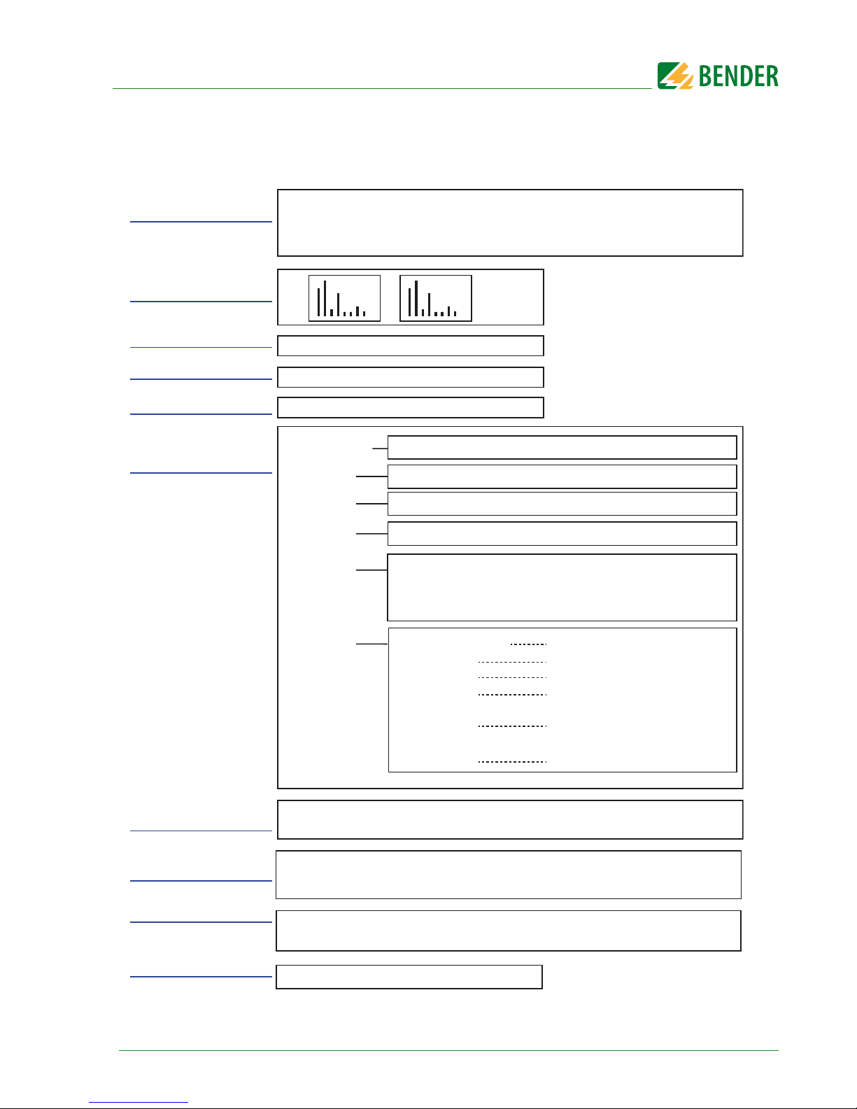
Menu structure
1. Data meas. values
4. Pulser
3. History
5. Display
9. Info
History, Delete
Pulser, t
Impuls
R
NGR, INGR
HRG system
CT
NGR
Phase
monitor
Field calibration
U
sys
(L-L), f, I
NGR nom, RNGR nom
CT primary, CT secondary, CT connection
10. Alarm
Acknowledge, Reset, Test
R
NGR
, R
NGR rel
, Method, R
sense, Irms, Irms rel
, U
rms, Urms rel, Ifund,
I
fund rel
, U
fund, Ufund rel, Iharm
, I
harm rel
, U
harm
, U
harm rel, UL1L2
, U
L2L3
,
U
L3L1
, f, U
1-E rms
, U
2-E rms
, U
3-E rms
, T
6. HRG settings
7. Device settings
Language, Clock, Interface, Display, Password, Factory setting,
Software, Service
2. Harmonics
IU
Device information, Software information,
Clock and date information, Ethernet information
Earth fault relay
NGR relay
Trip relay
Analogue
Dig. in/out
Buzzer
Mode, Relay test
Mode, Relay test
Mode, Relay test
System OUT, Pulser OUT,
Pulser IN, Reset IN, Test IN
Buzzer alarm, Buzzer test
Mode, Function
U
NGR Trip
, I
NGR Trip
, >R
NGR
, <R
NGR
, t
NGR trip
,
GF trip, t
GF trip
, t
restart,
Alarm stored,
Max. no. of restarts, Trip signal, Upper limit harmonics,
Lower limit harmonics
Method, PT primary, PT secondary
Phase monitor, PT primary, PT secondary
Response
values
System
settings
8. Commissioning
Setting Language, Setting Clock, Setting U
sys L-L
, f, I
NGR nom
,
R
NGR nom, CTprimary
, CT
secondary, CTConnection, Field calibration
Page 6
6
NGRM700_D00292_02_Q_XXEN/06.2018
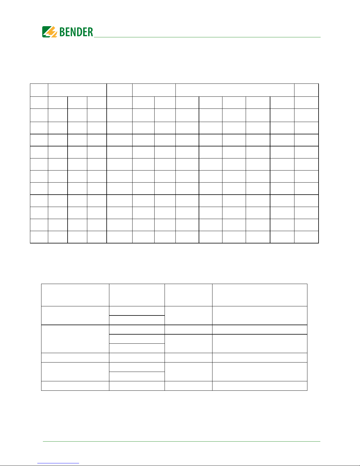
Recommended minimum value R
NGR
(tripping level 50 %)
Temperature range –40…+70 °C, field calibration at 25 °C
(Limited temperature range 0…+40 °C, field calibration at 25 °C)
Maximum trip times t(GFtrip) for the used CD-NGRM
The setting for t
GF trip
must under no circumstances be longer than the maximum possible operating
time of the CD-NGRM… coupling device.
The table shows an overview of the t(GFtrip) settings for the coupling device used:
CD1000/CD1000-2
CD1000-2
CD5000 CD14400
CD25000
U
sys
400 V 600 V 690 V 1000 V 2400 V 4200 V 6000 V 6600 V 7200 V 11000 V 14400 V 25000 V
I
NGR
1 A
231 346 398 577 1386
—
————— —
5 A
46 69 80 115 277
485
693 762 831 1270 1663 —
10 A
(23 Ω) 35 40 58 139
242
346 381 416 635 831 1443
15 A
(15 Ω) (23 Ω) (27 Ω) 38 92
162
231 254 277 423 554 962
20 A
— (17 Ω) (20 Ω) 29 69
121
(173 Ω) 191 208 318 416 722
25 A
——(16 Ω) (23 Ω) 55
97
(139 Ω) (152 Ω) (166 Ω) 254 333 577
30 A
———(19 Ω) (46 Ω)
81
(115 Ω) (127 Ω) (139 Ω) 212 277 481
40 A
——— —(35 Ω)
61
(87 Ω) (95 Ω) (104 Ω) (159 Ω) 208 361
50 A
——— —(28 Ω)
(48 Ω)
— (76 Ω) (83 Ω) (127 Ω) (166 Ω) 289
100 A
——— — —
(24 Ω)
————(83 Ω) (144 Ω)
U
sys
Coupling device
max. t
GF trip
(menu 6.5.7)
Ground fault trip setting (menu
6.5.6)
400… 690 V
CD1000
24 h on or off
CD1000-2
691…1000 V
CD1000 300 s on
CD1000-2
24 h on or off
CD5000
1001…4300 V CD5000 24 h on or off
4301…14550 V
CD14400
60 s on
CD25000
14551…25000 V CD25000 10 s on
Page 7
7
NGRM700_D00292_02_Q_XXEN/06.2018
Initial commissioning
The commissioning wizard (menu 8) queries the following parameters; additional settings: menu 6.
Language (8.2) Select
Date (8.3) Set
Time (8.4) Set
Usys L-L (8.5) System voltage
Frequency (8.6) 50 or 60 Hz
INGR nom (8.7)
RNGR nom (8.8)
CT primary (8.9)
CT secondary (8.10)
CT connection (8.11) 50 mA or 5 A
Field calibration (8.12)Start or do not start
1. Setting the response values (menu 6.5)
Trip threshold value for voltage (
U
NGR
)
Trip threshold value for current (
I
NGR
)
Trip threshold values for resistance (
R
NGR
)
2. System settings of the relays (menu 6.6)
The factory setting for the relays is fail-safe. In the case of self test, the relays change state.
3. Field calibration (menu 6.7)
After the parameters have been entered, a field calibration can be carried out to set R
NGR
= R
NGR nom
.
4. Trip signal RMS, fundamental frequency, harmonics
Which measured value causes tripping can be selected via the "Trip signal" parameter (menu 6.5.11). A
trip signal can be:
RMS
: The r.m.s. value of I or U over the entire frequency range (up to approx. 3.8 kHz).
Fundamental frequency
: Only the r.m.s. component of the fundamental frequency (50 or 60 Hz).
Harmonics:
The filtered r.m.s. value on the set harmonics where
H0 = DC; H1 = fundamental frequency; H2 = 2 x fundamental frequency; …H32 = 32 x funda-
mental frequency
Low trip threshold values: may lead to false tripping.
High trip threshold values: the device may not trip at all
Fail-safe: The relay is energised during normal operation and is deactivated in the event
of a fault.
Non-fail-safe: The relay is de-energised in normal operation and is activated in the event
of a fault.
In the "Harmonics" measured value display (menu 2) all spectral lines are always
displayed. This is independent of the trip signal setting.
On the standard display, the trip signal is indicated as resistance (in Ω or %) or as
current (in A or %). The setting is entered in "Display" (menu 5).
Page 8
© Bender GmbH & Co. KG
All rights reserved.
Reprinting only with permission
of the publisher.
Subject to change!
Photos: Bender Archiv
Bender GmbH & Co. KG
Postfach 1161 • 35301 Gruenberg • Germany
Londorfer Str. 65 • 35305 Gruenberg • Germany
Tel.: +49 6401 807-0 • Fax: +49 6401 807-259
E-Mail: [email protected] • www.bender.de
E493737
5. Initial measurement
During device start, all measured values are recorded.
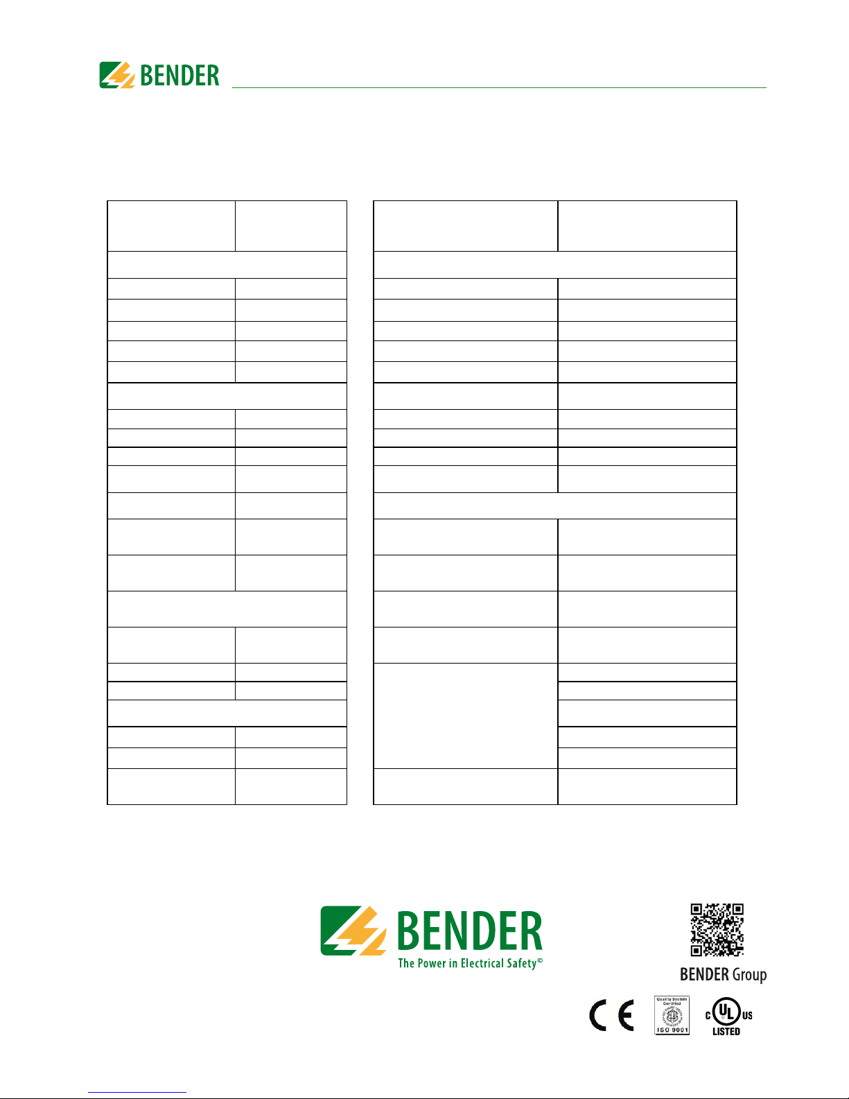
Factory settings
Menu
Fact.
settings
Menu
Fact.
settings
Menu 6.1: HRG system Menu 6.5: Response values
1. U
sys (L-L)
400 V
4. < R
NGR
50 %
2. CD-NGRM CD1000
5. t
NGR trip
0 s
3. Frequency 50 Hz
6. Ground fault trip on
4. I
NGR nom
5 A
7. t
GF trip
5 s
5. R
NGR nom
470 Ω 8. Alarm stored on
Menu 6.2: CT
9. t
restart
5 s
1. CT primary 600
10. Restart count 2
2. CT secondary 1 11. Trip signal RMS
3. CT connection 50 mA 12. Upper limit harmonic 32
Menu 6.3: NGR
13. Lower limit harmonic 0
1. Method auto
Menu 6.6: System settings
2. PT primary 1 1. Ground-fault relay
Mode fail-safe
Rel. test on
3. PT secondary 1 2. NGR relay
Mode fail-safe
Rel. test on
Menu 6.4: Phase monitor
3. Trip relay
Mode fail-safe
Rel. test on
1. Phase monitor on 4. Analogue
Mode 4-20 mA
Function R NGR
2. PT primary 1
5. Dig. in/out.
System OUT fail-safe
3. PT secondary 1 Pulser OUT non-fail-safe
Menu 6.5: Response values
Pulser IN active high
1. U
NGR trip
60 % RESET IN active high
2. I
NGR trip
60 % TEST IN active high
3. > R
NGR
150 % 6. Buzzer
Buzzer alarm off
Buzzer test on
 Loading...