

Page 1

DE EN
Handbuch/Manual
MK2007CBM(T)
Melde- und Prüfkombination für
Deutsch English
medizinisch genutzte Bereiche
Bestimmungsgemäße Verwendung
Die Melde- und Prüfkombination MK2007CBM(T) dient zur Anzeige von Betriebs- und Fehlermeldungen von Isolationsüberwachungsgeräten 107TD47 und isoMED427P.
Normen
Die Melde-und Prüfkombination MK2007CBM(T) entspricht den
Gerätenormen und Errichtungsbestimmungen für elektrische
Anlagen in medizinisch genutzten Räumen:
IEC 60364-7-710:2002,
HD 60364-7-710: 2012-10,
DIN VDE 0100-710:2012-10; VDE 0100-710:2012-10
Sicherheitshinweise allgemein
Bestandteil der Gerätedokumentation sind neben diesem Datenblatt die beiliegenden „Wichtigen sicherheitstechnischen Hinweise für Bender-Produkte“.
Funktionsbeschreibung
Anzeigen
MK2007CBM(T), Adress-Bereich 1…90 ab SW-Version 1.90, stellt
die von den Isolations-Überwachungsgeräten über den BMS-Bus
ausgegebene Alarmmeldungen und Messwerte auf den Siebensegment-Anzeigen und LEDs dar. Zusätzlich kann die Alarmmeldung eines weiteren Isolations-Überwachungsgerätes für OPLeuchten-Kreise angezeigt werden. Die Meldung „OP“ erscheint
dann alternierend zum aktuellen Laststrom-Messwert auf dem
Display „TRANSFORMER LOAD %“ / „I/%“.
Die Siebensegment-Displays zeigen an:
● Isolationswerte in kΩ
● Verhältnis des momentanen Laststroms zum maximal
erlaubten sekundärseitigen Laststrom I in %.
Durch LEDs angezeigt werden:
● Betriebsbereitschaft (grün)
● Isolationsfehler (gelb)
● Überstrom (gelb)
● Übertemperatur (gelb)
● Gerätefehler des MK2007CBM(T) und des Isolationsüber-
wachungsgerätes
Selbsttest
Mit Hilfe der Taste „TEST“ kann ein Selbsttest des MK2007CBM(T)
und des zugehörigen Isolationsüberwachungsgerätes gestartet
werden. Einzelheiten finden Sie in der Dokumentation des Isolationsüberwachungsgerätes.
Betätigen Sie die Taste „TEST“ länger als eine Sekunde. Als Folge
werden alle Segmente und Dezimalpunkte der Anzeigen aktiviert, zusätzlich leuchten alle LEDs. Nach Loslassen der „TEST“Taste, wird der Lampentest beendet. Das angeschlossene Isolationsüberwachungsgerät bekommt gleichzeitig über den BMSBus den Auftrag, einen eigenen Selbsttest durchzuführen. Die
Alarme werden auf den Displays und den LEDs der Meldekombination nach einigen Sekunden angezeigt. Zusätzlich ertönt der
interne Summer. Danach schaltet die Meldekombination wieder
Remote alarm indicator and
test combination for
medically used rooms
Intended use
The MK2007CBM(T) alarm indicator and test combination is used
to indicate operating and fault messages of insulation monitoring devices 107TD47 and isoMED427P.
Standards
The MK2007CBM(T) alarm indicator and test combination complies with the following device standards and regulations for
erection of electrical equipment in medical locations:
IEC 60364-7-710:2002,
HD 60364-7-710: 2012-10
DIN VDE 0100-710:2012-10; VDE 0100-710:2012-10
General safety information
In addition to this data sheet, the documentation includes the
supplementary sheet “Important safety instructions for Bender
products“.
Function
Indications
The alarm and operating messages from the insulation monitoring devices are duplicated by the MK2007CBM(T), address range
1…90, software version 1.90 or higher, and indicated on a sevensegment display and by LEDs. In addition, an alarm message from
an additional insulation monitoring device for operating theatre
lamp circ uits can be indi cated. I n this case, the indication “OP“ appears alternately with the current load current measuring value
on the display “TRANSFORMER LOAD %“ / “I/%“.
The seven-segment display indicates:
● The insulation resistance in kΩ
● The ratio of the instantaneous load current to the maxi-
mum permissible secondary-load current I in %.
LEDs indicate:
● Readiness for operation (green)
● Insulation faults (yellow)
● Overcurrent (yellow)
● Overtemperature (yellow)
● Device fault MK2007CBM(T) and insulation monitoring
device
Self test
By pressing the “TEST“ button, a self test of the MK2007CBM(T)
and the associated insulation monitoring device can be carried
out. For details refer to the documentation of the insulation monitoring device.
Press the “TEST“ button for at least 1 second. All segments and
decimal points on the display will be activated, in addition all
LEDs light up. After releasing the “TEST“ button, the lamp test is
completed. At the same time, the connected insulation monitoring device is being requested via the BMS bus to carry out a self
test. After a few seconds, the alarm messages are indicated on the
displays and by the LEDs of the alarm indicator and test combination. In addition the internal buzzer sounds. Afterwards the alarm
indicator and test combination returns to normal operation
MK2007CBM_D00218_01_M_DEEN/10.2015
1
Page 2
MK2007CBM(T)
in den Normalbetrieb. Die Meldungen des Selbsttests kommen
nur an der Melde- und Prüfkombination zur Anzeige, an der der
Test ausgelöst wurde.
Alarm-Summer-Stummschaltung
Drücken der Taste „Mute“ / bewirkt Stummschaltung des
Summers. Durch Parametereinstellung kann eine Reaktivierung
des Summers nach einer einstellbaren Zeit gewählt werden.
Parametrieren
Die Melde- und Prüfkombination MK2007CBM(T) verfügt über
ein Menü zur Einstellung der eigenen Parameter.
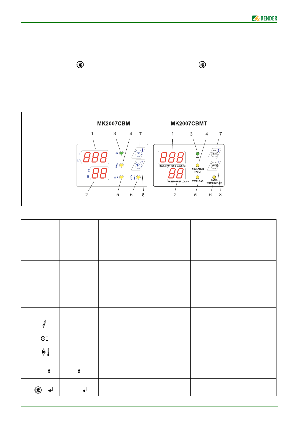
Anzeige- und Bedienelemente
mode. The alarm messages of the self test are only indicated on
that alarm indicator and test combination where the test was initiated.
Alarm buzzer mute
Pressing the “Mute“ / button results in buzzer mute. A parameter can be selected to reactivate the buzzer after a preset
time.
Setting
The MK2007CBM(T) alarm indicator and test combination provides a menu for setting customer-specific parameters
Operating and display elements
Elemente/
elements
CBM
1Display: „R“
2Display: „I“
3 LED „ON“ LED “ON“ Betriebsanzeige Power ON indication
4
LED
5
LED
6
LED
Taste/button
7
“TEST“ /
Tas te /b utt on
8
/
Element/
elements CBMT
Display: “INSULATION RESISTANCE
kΩ“
Display: “TRANSFORMER LOAD %“
LED “INSULATION
FAU LT“
LED “OVERLOAD“ Alarmmeldung: Überstrom Alarm message: overload
LED “OVERTEMPERATURE“
Taste/button
“TEST“ /
Tas te /b utt on
“MUTE“ /
Anzeige des überwachten Isolationswiderstandes in kΩ.
Im Menü-Modus: Menüpunkt
Anzeige des gemessenen Trenntransformator-Laststroms in %. Bei Anschluss eines
zusätzlichen Isolationsüberwachungsgerätes zur
OP-Leuchten-Überwachung an das 107TD47 bzw.
isoMED427P, wird dessen Alarmmeldung durch die
Anzeige „OP“ alternierend zur Laststromanzeige
dargestellt.
Im Menü-Modus: Einstellwert
Alarmmeldung: Isolationsfehler Alarm message: insulation fault
Alarmmeldung: Übertemperatur Alarm message: overtemperature
Testauslösung für Selbsttest und für angeschlossenes Isolationsüberwachungsgerät.
Im Menü-Modus: Cursor-Funktion
Stummschaltung Alarm-Summer
Im Menü-Modus: Return-Funktion
Bedeutung Meaning
Indication of the monitored insulation
resistance in kΩ.
In the menu mode: submenu
Indication of the measured isolating transformer load in %. When an additional
insulation monitoring device is connected to
the 107TD47 resp. isoMED427P for operatingtheatre-lamp monitoring, its alarm message
“OP“ will be indicated alternating to the load
current indication.
In the menu mode: setting value
Initiating the self test and the test for the connected insulation monitoring device.
In the menu mode: cursor function
Alarm buzzer mute
In the menu mode: return function
2
MK2007CBM_D00218_01_M_DEEN/10.2015
Page 3
MK2007CBM(T)
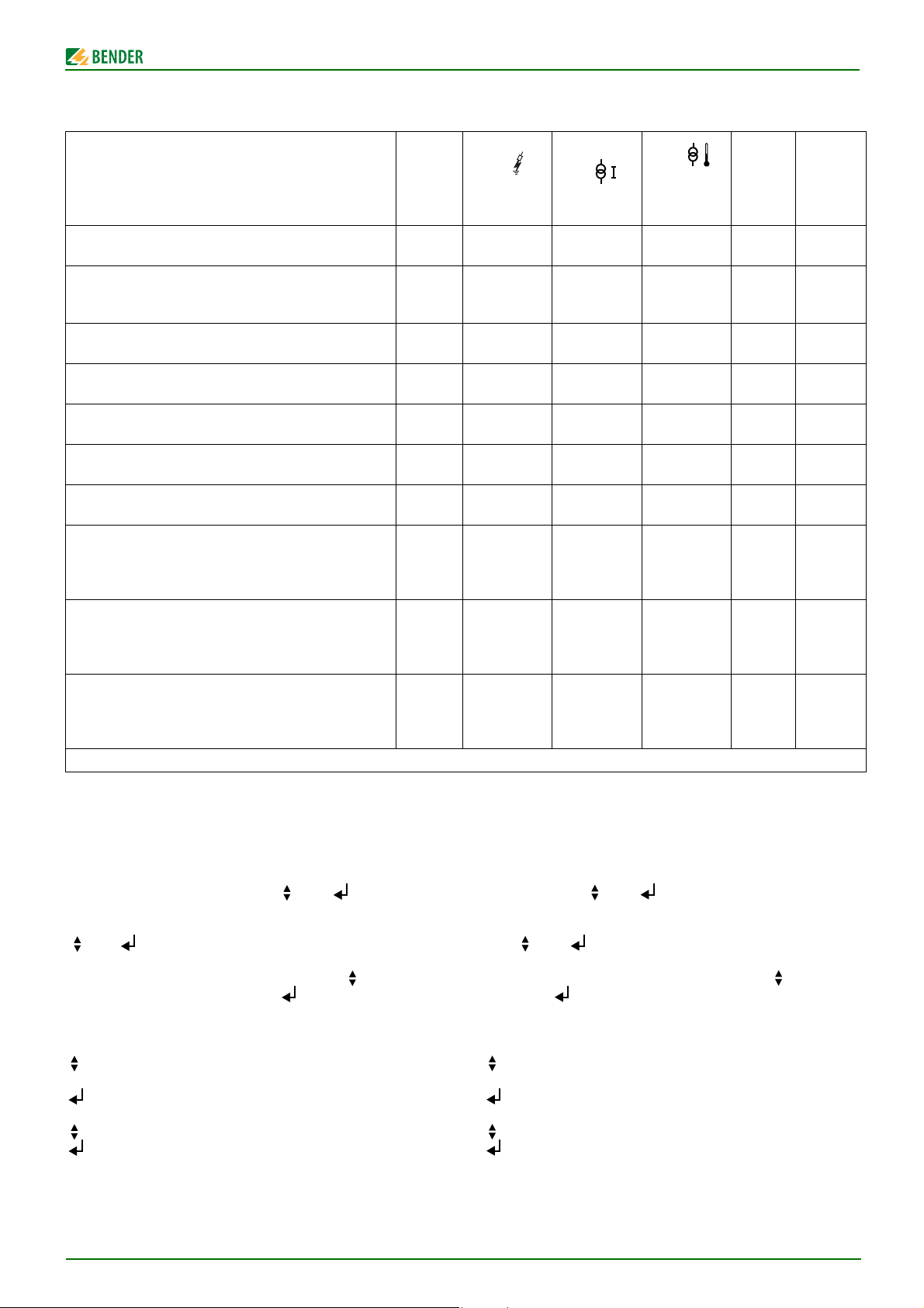
Fehler-/Alarmmeldungen des MK2007CBM(T)
Fehlermeldungen/
Fault indications
Isolationsfehler (107TD47 bzw. isoMED427P) /
Insulation fault (107TD47 resp. isoMED427P)
Isolationsfehler OP-Leuchtenkreis /
Insulation fault operating theatre lamp
Laststrom zu hoch /
Excessive load current
Übertemperatur Trenntrafo /
Overtemperature isolating transformer
Anschlussfehler Wandler /
Connection fault transformer
Anschlussfehler E/KE /
Connection E/KE to PE interrupted
Anschlussfehler L1/L2 gegen Netz /
Connection L1/L2 to system interrupted
Isometer antwortet nicht oder Isometer meldet:
Gerätefehler (siehe Isometer Datenblatt) /
Isometer doesn’t respond or Isometer signals:
Device fault (see Isometer data sheet)
Keine Verbindung zum BMS-Bus Master (MK2007CBM(T) im
Slave-Betrieb). /
No connection to BMS bus Master (MK2007CBM(T) in slave
mode).
Daten-Kollision auf dem BMS-Bus, z.B. durch doppelt vergebene Adresse. /
Data collision on the BMS bus, e.g. due to double address
assignment.
- = beliebig
Buzzer
ein/
on
ein/
on
ein/
on
ein/
on
ein/
on
ein/
on
ein/
on
ein/
on
ein/
on
aus/
off
MK2007CBM(T) fault and alarm messages
LED
INSULATION
FAU LT
ein/
on
ein/
on
-
-
-
-
blinkend/
flashing
blinkend/
flashing
blinkend/
flashing
blinkend/
flashing
blinkend/
flashing
blinkend/
flashing
LED
OVERLOAD
-
-
-
-
ein/
on
-
-
-
-
-
-
-
-
aus
off
blinkend/
flashing
blinkend/
flashing
LED
OVER-
TEMPERA-
TURE
-
-
-
-
-
-
ein/
on
-
-
-
-
-
-
aus
off
blinkend/
flashing
blinkend/
flashing
LED „ON“
blinkend/
flashing
blinkend/
flashing
blinkend/
flashing
blinkend/
flashing
blinkend/
flashing
blinkend/
flashing
Displays
„R“, „I“
-
-
-
-
-
-
-
-
Wer t/
value
Wert/
value/
“I“:“OP“
Wer t/
value
Wer t/
value
“Er“
“Er“
“Er“
“Er“
“Er“
“Er“
Menüeinstellung/Werkseinstellung
Alle Parameter werden mit Hilfe eines Menüs geändert. Die Menüsteuerung erfolgt über die Tasten und .
Einstieg ins Menü / Ausstieg aus dem Menü
und gleichzeitig länger als 3 Sekunden drücken.
Im oberen Display erscheint „Ec“ für Escape.
Von hier aus können Sie sich entweder mit der Taste weiter
durch das Menü bewegen oder mit aussteigen. Wird für 90
Sekunden keine Taste betätigt, erfolgt automatischer Ausstieg.
Einstellen eines Parameters
Wählen Sie den Parameter aus dem oberen Display laut un-
tenstehender Tabelle aus.
Bestätigen Sie den ausgewählten Parameter. Im unteren
Display blinkt der aktuelle Wert des Parameters.
Stellen Sie den gewünschten Wert des Parameters ein.
Bestätigen Sie die Einstellung.
MK2007CBM_D00218_01_M_DEEN/10.2015
Menu setting/Factory setting
All the parameters are changed by means of a menu. The menu is
controlled by the and keys.
Accessing / leaving the menu
Press and simultaneously for more than 3 seconds.
“Ec“ for Escape appears in the upper display.
From here you can move through the menu with or leave the
menu with . If no key is activated for 90 seconds, the menu is
quit automatically.
Setting the parameter
Choose the parameter from the upper display according to
the table below.
Confirm the selected parameter. The current parameter
value is flashing in the lower display.
Choose the appropriate parameter value.
Confirm the selected parameter.
3
Page 4

MK2007CBM(T)
DANGER
GEFAHR
Parameter
Display
“R“
Ec Ausstieg aus dem Menü Leaving the menu - -
Ad BMS-Adresse MK2007… ändern
BMS-Adresse für meldendes
Isolationsüberwachungsgerät
Ar
Sr
Sn Summer-Lautstärke auswählen Selecting the buzzer loudness “Hi“/“Lo“ “Hi“
auswählen
Durch diese Adresse wird auch festgelegt,
welches Isometer auf Test reagiert.
Sammelquittierung einschalten
Ist „Sr“ an einem MK eingeschaltet, so führt
das Betätigen der „Mute“-Taste an einem
anderen MK mit gleicher Ar-Einstellung
zum Stummschalten des Summers.
Bedeutung Meaning
Changing the BMS address of
MK2007…
Selecting the alarm address of the
insulation monitoring device indicating
the alarm messages
This address is also used to choose the insulation monitoring device that is to respond
to test.
Activating common alarm reset
If “Sr“ of one MK is set to “On“ and the
“Mute“ button is pressed at another MK with
the same Ar-setting, the buzzer of that MK
will be muted.
Einstellbereich/
Setting range
1 … 90
(ab Software-
Version 1.60/
SW version 1.60
or higher)
1 … 90
(ab Software-
Version 1.70/
SW version 1.70
or higher)
“--“/“On“ “--“ (aus/off)
Werkseinstellung
Factory setting
1 / (Master)
3
Wiederholungszeitraum für den
Or
Ir
F Anzeige der Firmware Version Indication of the firmware version - -
Summer wählen nach
Stummschaltung des Überstrom bzw.
Übertemperatur Alarms
Wiederholungszeitraum für den
Summer wählen nach
Stummschaltung der
Isolationsfehlermeldung
Montage und Anschluss
Gefahr eines elektrischen Schlages!
Stellen Sie vor Einbau des Gerätes und vor Arbeiten an den Anschlüssen des Gerätes sicher, dass
die Anlage spannungsfrei ist.
Wird dies nicht beachtet, so besteht für das Personal die Gefahr eines elektrischen Schlages. Außerdem drohen Sachschäden an der elektrischen
Anlage und die Zerstörung des Gerätes.
Selecting the repetition period for the
buzzer alarm after muting the
overcurrent and overtemperature
alarm
Selecting the repetition period for the
buzzer alarm after muting the
insulation fault alarm
Mounting and connection
Risk of electric shock!
Before fitting the device and prior to working on
the device connections, make sure that the power
supply has been disconnected.
Failure to comply with this requirement increases
the risk of exposing the personnel to an electric
shock. Furthermore, the electrical installation
may be damaged and the device destroyed beyond repair.
“--“/1 … 99
minutes
“--“/1 … 99
minutes
“--“(aus/off)
“--“ (aus/off)
4
MK2007CBM_D00218_01_M_DEEN/10.2015
Page 5

MK2007CBM(T)
MK2007CBM
145
170 mm
85
2,5 ... 5
15
5 mm
17
67
57
Maßbild
Montage
Die Melde- und Prüfkombination eignet sich für Schraubmontage in den Varianten:
● Unterputzmontage
Hierfür benötigen Sie die mitgelieferte Unterputzdose.
● Hohlwand- und Kabelkanal-Montage
Hierfür benötigen Sie die mitgelieferte Unterputzdose und
einen Befestigungssatz mit der Bestellnummer B923711
● Schalttafel-Montage
Hierfür benötigen Sie die mitgelieferte Unterputzdose und
einen Befestigungssatz mit der Bestellnummer B923780.
Die Schalttafelöffnung muss 160 x 75 mm betragen
Dimension diagram
Mounting
The alarm indicator and test combination is suitable for screw
mounting. Available options are:
● Flush mounting
Required accessories:
a flush mounting box (supplied with the device)
● Wall mounting and cable-duct mounting
Required accessories:
a flush-mounting box (supplied with the device)
and a fixing set (to be ordered under No. B923711).
● Panel mounting type:
Required accessories:
a flush-mounting box (supplied with the device)
and a fixing set (to be ordered under No. B923780).
Dimensions of the switchboard cutout:160 x 75 mm.
Anschlussplan
Us = 230 V
AC 50 ... 60 Hz
OP *
IN T1
*
* Nur 107TD47: Optionales zusätzliches Isolationsüberwachungs-
gerät für OP-Leuchtenkreise.
** Isometer = 107TD47 oder isoMED427P
MK2007CBM_D00218_01_M_DEEN/10.2015
**
AB
120 Ω
2 x 6 A
AN450
BMS-Bus
max. 1200 m
Wiring diagram
V2
U2
MK2007CBMIsometer
MK2007CBM
ABAB
120 Ω
* 107TD47 only: Optionally additional insulation monitoring
device for operating theatre lamp circuits
** Isometer = 107TD47 or isoMED427P
V2
U2
5
Page 6

MK2007CBM(T)
Anschluss
Das Anzugsmoment für alle Klemmschrauben beträgt
0,5 … 0,6 Nm.
1. Stromversorgung (Standardkabel)
Die Stromversorgung erfolgt über das Netzteil AN450. Für
die Zuleitung vom Netzteil zur Melde- und Prüfkombination gelten folgende Leitungslängen:
Querschnitt 1 MK2007 2 MK2007 3 MK2007
0,8 mm² 750 m 400 m 150 m
1,5 mm² 1500 m 700 m 250 m
2,5 mm² 2300 m 1200 m 400 m
2. BMS-Bus
Der BMS-Bus ist eine RS485-Schnittstelle mit Bender-internem Protokoll.
Verbinden Sie die Klemmen A und B des Gerätes mit dem
BMS-Bus, wie im Anschlussplan dargestellt. Beachten Sie
dabei den Beipackzettel „BMS-Bus“.
10 Goldene Regeln für BMS-Netzwerke
● Jedes Netzwerk muss von einem MASTER geführt werden.
● In jedem Netzwerk darf nur ein MASTER vorhanden sein.
● Jedem Busteilnehmer muss eine eindeutige Adresse zuge-
wiesen werden.
● Adressen dürfen niemals doppelt vergeben werden.
● Das Netzwerk muss an seinen beiden Enden mit
120 Ω-Abschlusswiderständen terminiert werden.
● Das Netzwerk darf eine maximale Leitungslänge von
1200 m nicht überschreiten, sofern keine Zwischenverstärker eingesetzt sind.
● Die Anzahl der Geräte innerhalb eines Netzwerkes darf 32
nicht übersteigen, sofern keine Zwischenverstärker eingesetzt sind.
● Das Netzwerk muss eine günstige Topologie (ohne Ver-
zweigungen) aufweisen.
● Die Busleitung ( J-Y(St)Y 2x0,6) muss abgeschirmt und ein-
seitig geerdet sein.
● Niemals Busklemmen A und B vertauschen.
Connection
The tightening torque for all terminal screws is 0.5 … 0.6 Nm.
1. Power supply (standard cable)
The power supply is provided by the AN450 power supply
unit. The maximum cable lengths from the power supply
unit to the alarm indicator and test combination are indicated in the table below:
Wire cross
section
1 MK2007 2 MK2007 3 MK2007
0.8 mm² 750 m 400 m 150 m
1.5 mm² 1500 m 700 m 250 m
2.5 mm² 2300 m 1200 m 400 m
2. BMS bus
The BMS bus is an RS485 interface with internal Bender
protocol.
Connect the terminals A and B of the device to the BMS
bus as illustrated in the wiring diagram below considering
the instruction leaflet "BMS bus".
Ten golden rules for the design of BMS networks
● Every network must be controlled by a MASTER.
● Only one MASTER may exist in each network.
● A unique address must be assigned to each bus node.
● Be sure not to assign any address twice.
● The network must be terminated at both ends with
120 Ω terminating resistors.
● The line lengths of the network must not exceed 1200 m,
unless intermediate amplifiers are used.
● The number of devices applied in a network must not
exceed 32 unless intermediate amplifiers are used.
● The network must provide a favourable topology (without
branches).
● The bus cable ( J-Y(St)Y 2x0.6) must be shielded and single
ended connected to earth.
● Never interchange bus terminals A and B.
Häufige Konfigurationen
6
Common configurations
MK2007CBM_D00218_01_M_DEEN/10.2015
Page 7

MK2007CBM(T)
CAUTION
DANGER
VORSICHT
GEFAHR
Inbetriebnahme
Schließen Sie den BMS-Bus an und konfigurieren Sie die BMS-Geräte unter Beachtung der 10 Goldenen Regeln für den Anschluss
von BMS-Netzwerken.
Beachten Sie die Werkseinstellung der Parameter,
insbesondere die Einstellung der BMS-Adressen
für die Melde- und Prüfkombination und das Isolationsüberwachungsgerät und die „10 Goldenen
Regeln“ auf Seite 6 zum Aufbau von BMS-Netzwerken.
Nach korrektem Anschluss der Speisespannung U
und des BMS-
S
Busses sowie korrekter Adressierung erscheint auf den Siebensegment-Anzeigen der aktuell gemessene Isolationswiderstand
und die prozentuale Angabe des sekundären Laststroms.
Führen Sie einen Funktionstest der Meldekombination durch. Starten Sie dazu den Selbsttest der
MK2007CBM(T).
Bestellangaben
Typ Bezeichnung Art.Nr.
Melde- und Prüf-
MK2007CBM
MK2007CBMT
MK-Zubehör Unterputzgehäuse B923710
MK-Zubehör Schalttafeleinbausatz B923780
MK-Zubehör Hohlwandeinbausatz B923711
kombination
(Frontfolie mit Symbolen)
Melde- und Prüfkombination
(Frontfolie mit Text)
B923813
B923801
Commissioning
Connect the BMS bus to the supply voltage. Configurate the BMS
devices under consideration of the 10 Golden Rules for the design of BMS networks.
Observe the factory setting of the parameters, in
particular the BMS address settings for the alarm
indicator and test combination and the insulation
monitoring device as well as the „Ten golden
rules“ on page 6 for designing a BMS network.
Once the supply voltage U
and the BMS bus is successfully con-
S
nected and after correct address assignment, the currently measured insulation resistance and the percentage indication of the
secondary load current appears on the seven-segment display.
Check the function of the alarm indicator by starting the self test of the MK2007CBM(T).
Ordering details
Type Designation Art. No.
Alarm indicator and test
MK2007CBM
MK2007CBMT
MK accessory Flush-mounting enclosure B923710
MK accessory Panel mounting kit B923780
MK accessory Dry wall installation kit B923711
combination
(front foil with symbols)
Alarm indicator and test
combination
(front foil with text)
B923813
B923801
Technische Daten
Isolationskoordination nach IEC 60664-1:
Bemessungsspannung ...................................................................................................... AC 250 V
Bemessungsstoßspannung/Verschmutzungsgrad .............................................................. 4 kV/3
Spannungsbereiche
Versorgungsspannung US .................................................................................. ............ AC/DC 24 V
Frequenzbereich von U
Arbeitsbereich von U
Eigenverbrauch ................................................................................................................... ≤ 2,5 W
Anzeige- und Bedienelemente
Display R, dreistellig ................................................................. .............. Isolationswiderstand in kΩ
Anzeigebereich für isoMED427P.................................................................................. 10…999 kΩ
Anzeige bei R < 10 kΩ..................................................................................... 0 ( Isolationsfehler)
Anzeige bei R ≥ 999 kΩ.............................................................................................................999
Display I, zweistellig .................................................. ...................... Transformator-Laststrom in %
LEDs........................................................... ............. ON, Isolationsfehler, Überlast, Übertemperatur
Tasten............................................................................... Isometertest, Summer-Stummschaltung
Summermeldung ................. ...................................................... quittierbar, mit Neuwertverhalten
Summerwiederholung ...................................................... ................................................ einstellbar
Schnittstellen
Schnittstelle/Protokoll ................................................................................. ................... RS485/BMS
Baud Rate ........................................................................................................................... 9,6 kBit/s
Leitungslänge .................................................................................................................. ≤ 1200 m
MK2007CBM_D00218_01_M_DEEN/10.2015
............................................................................................. 0, 50…60 Hz
S
..................................................................................................... 12 … 28 V
S
Technical data
Insulation coordination in accordance with IEC 60664-1:
Rated insulation voltage ..................................................................................................... AC 250 V
Rated impulse withstand voltage/contamination level ...................... ................................. 4 kV/ 3
Voltage ranges
Supply voltage US ................................................................................. .......................... AC/DC 24 V
Frequency range U
Operating range U
Power consumption ............................................................................................................ ≤ 2.5 W
Indicating and operating elementsfe
Display R, three-digit................................................................ ............... Insulation resistance in kΩ
Display range for isoMED427P..................................................................................... 10…999 kΩ
Display at R < 10 kΩ..........................................................................................0 (Insulation fault)
Display at R ≥ 999 kΩ................................................................................................................999
Display I, two-digit ............................................. .......................................... Trans former load in %
LEDs...................................................................... ON, insulation fault, overload, over temperature
Buttons................................................................................................... Isometer test, buzzer mute
Buzzer alarm ............................................................................... .............with buzzer mute function
Buzzer repeat factor .......................................................................................................... adjustable
Interface
Interface/Protocol............................................................................................................RS485/BMS
Baud rate ........... ..................................................................................................................9.6 kBit/s
Cable length................ ...................................................................................................... ≤ 1200 m
.................................................................................................... 0, 50…60 Hz
S
.................................................................................. ........................12 … 28 V
S
7
Page 8

MK2007CBM(T)
BENDER Group
Leitung (paarweise verdrillt, geschirmt, Schirm einseitig an PE) .....................................................
....................................................................................................... empfohlen: J-Y(St)Y min. 2 x 0,8
Abschlusswiderstand.............. .................................................................................. .. 120 Ω (0,5 W)
Geräteadresse, BMS-Bus ....................................................................................................... 1
Werkseinstellung Geräteadresse ................................................................................... ...1 (Master)
Allgemeine Daten
EMV-Störfestigkeit............................................................................................. nach EN 61000-6 -2
EMV-Störaussendung .................................................................. ..................... nach EN 61000-6-4
Klimaklassen nach IEC 60721
Ortsfester Einsatz .......................................................................................................................... 3K5
Transport ................................................ .......................................................................................2K3
Langzeitlagerung .................................................. ........................................................................1K4
Arbeitstemperatur ...................................................................................................... -5 … +55 °C
Mechanische Beanspruchung nach IEC 60721
Ortsfester Einsatz ........................................................................................................................ 3M4
Transport ................................................ ..................................................................................... 2M2
Langzeitlagerung .................................................. ...................................................................... 1M3
Betriebsart .....................................................................................................................Dauerbetrieb
Einbaulage ........................ ............................................................................. ........................beliebig
Anschlussart............................................................................................................... Steckklemmen
Anschlussvermögen (Versorgungsspannung, BMS-Bus
starr/flexibel/Leitergrößen ......................................... 0,2 … 2,5 / 0,2 … 2,5 mm² / 24-12 AWG
flexibel mit Aderendhülse ohne/mit Kunststoffhülse .................. 0,25 … 2.5 / 0,25 … 2,5 mm²
Mehrleiteranschluss (2 Leiter gleichen Querschnitts)
starr/flexibel.......................................................................................... 0,2 … 1 / 0,2 … 1,5 mm²
flexibel mit Aderendhülse ohne Kunststoffhülse.....................................................0,25 … 1 mm²
flexibel mit TWIN-Aderendhülse mit Kunststoffhülse ........................................... 0,5 … 1,5 mm²
Schutzart, eingebaut (DIN EN 60529) ....................................................................................... IP50
Schutzart, Klemmen (DIN EN 60529) ........................................................................................ IP20
Gehäusetyp .......................................................................................................... Unterputzgehäuse
Montage..................................................................................... Unterputz, Kabelkanal, Schalttafel
Entflammbarkeitsklasse ................................................................... ................................. UL94 V-0
Gewicht ............................................................................................................................... ≤ 150 g
…90
Cable (twisted pair, shielded, shield connected to PE on one side) .................................................
................................................................................. ...............recommended: J-Y(St)Y min. 2 x 0.8
Terminating resistor .................................................................................................. 120 Ω (0.5 W)
Device address, BMS-Bus ............................................................................................. ......... 1…90
Factory setting device address .............................. ............................................................ 1 (Master)
General data
EMC immunity ..................................................................................... according to IEC 61000-6-2
EMC emission ...................................................................................... according to IEC 61000-6-4
Classification of climatic conditions IEC 60721
Stationary use ...............................................................................................................................3K5
Transport ......................................................................................................................................2K3
Storage................................................................... .......................................................................1K4
Operating temperature .............................................................................................. -5 … +55 °C
Classification of mechanical conditions IEC 60721
Stationary use ..............................................................................................................................3M4
Transport................................................................................................ ......................................2M2
Storage................................................................... ......................................................................1M3
Operating mode .............................................................................................. continuous operation
Mounting position ......................................................................................................... any position
Connection details ................................................................................................ plug-in terminals
Connection properties
rigid/flexible/AWG ..................................................... 0.2 … 2,5 / 0.2 … 2.5 mm² / 24-12 AWG
flexible, with ferrule without/with plastic sleeve ............... .........0.25 … 2.5 / 0.25 … 2.5 mm²
Two conductors with the same cross section
rigid/flexible ......................................................................................... 0.2 … 1 / 0.2 … 1.5 mm²
flexible, with ferrule without plastic sleeve ............................................................. 0.25 … 1 mm²
flexible, TWIN ferrules with plastic sleeve.............................................................. 0.5 … 1.5 mm²
Degree of protection, build-in (EN 60529)............................................................................... IP 50
Degree of protection, terminals (EN 60529) ........................................................................... IP 20
Enclosure ......................................................................................................... flush-mounting type
Mounting type.............................................................. flush-mounting, cable-duct, switch board
Flammability class .............................................................................................................. UL94 V-0
Weight ................................................................................................................................. ≤ 150 g
Alle Rechte vorbehalten. Nachdruck und Vervielfältigung nur mit
Genehmigung des Herausgebers. Änderungen vorbehalten!
© Bender GmbH & Co. KG
Fotos: Bender Archiv. Photos: Bender archives.
Bender GmbH & Co. KG
Postfach 1161 • 35301 Grünberg • Germany
Londorfer Straße 65 • 35305 Grünberg • Germany
Tel.: +49 6401 807-0 • Fax: +49 6401 807-259
E-Mail: info@bender.de • www.bender.de
8
All rights reserved. Reprinting and duplicating only with
permission of the publisher. Subject to change!
© Bender GmbH & Co. KG
MK2007CBM_D00218_01_M_DEEN/10.2015
 Loading...