

Page 1
T M
Document NAE2028450 • 11.2012 • © Bender Inc. • Page 1/1 • Side 1/2Bender Inc. • USA: 800.356.4266 / 610.383.9200 / medical@bender.org • Canada: 800.243.2438 / 905.602.9990 / info@bender-ca.com • www.bender.org
MK2000CBM
Installation Bulletin / Reference Guide
This document is intended as a reference guide to installing and setting an MK2000CBM series remote
indicator. This document includes installation instructions and typical front plate display indications
of the device. For complete details, including installation, setup, settings, and troubleshooting, refer to
the LIM2010 user manual, document NAE2025010.
Only qualied maintenance personnel shall operate or service this equipment. These instructions
should not be viewed as sucient for those who are not otherwise qualied to operate or service
this equipment. This document is intended to provide accurate information only. No responsibility
is assumed by BENDER for any consequences arising from use of this document. This device series is
intended for use only with the BENDER LIM2010 Line Isolation Monitor.
Installation
Mounting
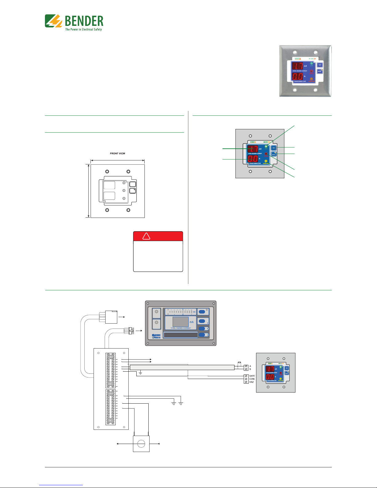
Two-gang plates provide four holes (Two at the top, two at the bottom) for screw mounting.
Use the provided screws for mounting. Refer to gure 1 for dimensions.
Figure 1 - Two-gang wall plate dimensions in inches (mm)
Front Panel Display
1. Green “SAFE” LED. Illuminates when the
connected LIM2010 is in the normal
condition.
2. Yellow “HAZARD” LED. Illuminates
when the connected LIM2010 is in the
alarm condition.
3. Yellow “OVERLOAD” LED. Illuminates
when the connected LIM2010’s transformer overload alarm is active.
4. TEST button. Initiates a self-test of the
connected LIM2010.
5. MUTE button with amber LED. Mutes
the audible alarm when in the alarm
condition. The amber LED indicates that
the audible alarm has been muted.
6. THC Digital Display. Shows the Total
Hazard Current in real-time.
7. Overload Digital Display. Shows the
transformer overload percentage in real-time.
1
4
5
2
3
6
7
Figure 3 - MK2000CBM diagram
Figure 2: Wiring Diagram, MK2000CBM
STW3 / STW4
CP-LIM2010
Connector Plate
L1 from
transformer
secondary
L1 to
load center
To load center
RS-485 cable: twisted, shielded pair
MK2000CBM
120 Ω
Termination
Resistor
SAFE
HAZARD
MUTE
ESC
TEST
RESET
MENU
LIM2010
To panel
ground bus
L1
L2
12VDC CM
A
B
RI1
K1/NC
K1/COM
K1/NO
SAFE
HAZARD
RI2
LIMGND
TEST
1S1
Z1/M+
1S2
Z2/MK2/COM
K2/NC
K2/NO
GND2
4.6“ (116.8)
4.55“ (115.6)
Wiring
MK2000CBM series remotes connect to a connector
plate assembly utilizing a two-wire RS-485 connection.
Ensure that the LIM2010 and corresponding connector
plate have already been installed.
Refer to gure 2 below for wiring diagram. The
MK2000CBM may only be used with type LIM2010 line
isolation monitor.
!
DANGER
• Disconnect all power before servicing.
• Reference NFPA 99 / CSA Z32 for
Installation Standard.
HAZARD OF ELECTRIC SHOCK,
EXPLOSION, OR ARC FLASH
Applicable Devices
This document applies to MK2000CBM remote indicators only.
Page 2
T M
Document NAE2028450 • 11.2012 • © Bender Inc. • Page 1/1 • Side 2/2Bender Inc. • USA: 800.356.4266 / 610.383.9200 / medical@bender.org • Canada: 800.243.2438 / 905.602.9990 / info@bender-ca.com • www.bender.org
MK2000CBM
Installation Bulletin / Reference Guide
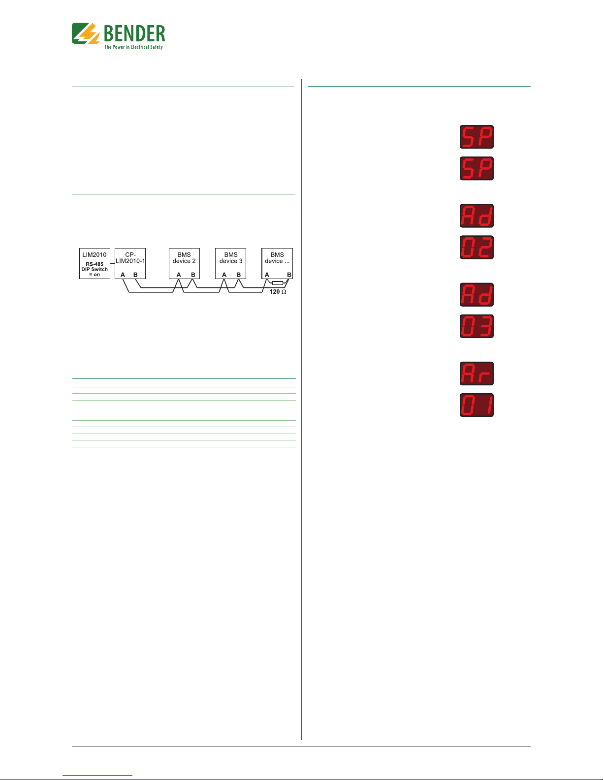
Connecting Multiple Remotes to a Single LIM2010
Up to two (2) MK2000CBM remotes may be connected to a single LIM2010. MK2000CBM series
remotes utilize a special RS-485 protocol for communication. Each remote must be assigned
a unique bus address for proper operation. Follow the procedure below to change the address for each remote indicator.
NOTE: The connected LIM2010 will be assigned address 1. A single connected MK2000CBM
will be assigned address 2. This is the factory default and will not require the below procedure.
An additionally connected remote must be assigned address 3 and will require the following
procedure.
Step 2: Changing the Address of the MK2000CBM
Follow the below procedure for changing the communication address of the MK2000CBM.
Step 1: Wiring Modifications
All remotes and LIM2010 are wired in series with each other via each device’s “A” and “B” terminals. ONLY devices at the beginning and the end of the chain require the termination resistor.
For the LIM2010, this resistor is activated via a switch on the device. For MK2000CBM remotes,
a 120 Ω resistor must be wired across the remote’s “A” and “B” terminals. Refer to Figure 4 for a
sample layout.
1) Hold the TEST and MUTE buttons simultaneously for at
least four (4) seconds. “SP” will display on both screens.
2) Push the TEST button until “Ad” is displayed in the top
screen, and two numbers (factory default “02”) is displayed
in the bottom screen. This number is the communication
address of the MK2000CBM remote.
3) Press the MUTE button. Press the TEST button until the
desired address is displayed on the screen. Press the MUTE
button to conrm this value.
4) Press the TEST button. “Ar” will display on the top screen,
and two numbers (factory default “01”) will display on
the bottom screen. This is the address of the connected
LIM2010 device. In most applications, this value will not
need to be changed. If so, skip to step 5. Otherwise, press
the MUTE button. Press the TEST button until the desired
LIM2010 address appears, and press MUTE again to conrm this value.
5) Cycle power to the MK2000CBM to nish.
Technical Data
Operating voltage 12V DC or 12V AC
Max. current 100 mA
Operation class continuous operation
Ambient temperature
when operating 0º C to +50ºC
when stored -25º C to +70º C
Connection screw terminal block
Conductor size AWG 30…12
Tightening torque 5…7 lb-in.
Mounting by screws
Weight 150 g
Figure 4 - Example communication bus layout
 Loading...