

Page 1
T M
Document NAE2028520 • 08.2015 • © Bender Inc. • Page 1/1 • Side 1/2Bender Inc. • USA: 800.356.4266 / 610.383.9200 / medical@bender.org • Canada: 800.243.2438 / 905.602.9990 / info@bender-ca.com • www.bender.org
MK2000(C)(P) Series
Installation Bulletin / Reference Guide
This document is intended as a reference guide to installing and setting a MK2000 series remote indicator. This document includes installation instructions and typical front plate display indications of
the device. For complete details, including installation, setup, settings, and troubleshooting, refer to
document NAE2025010, “LIM2010 User Manual.”
Only qualied maintenance personnel shall operate or service this equipment. These instructions
should not be viewed as sucient for those who are not otherwise qualied to operate or service
this equipment. This document is intended to provide accurate information only. No responsibility
is assumed by BENDER for any consequences arising from use of this document. This device series is
intended for use only with the BENDER LIM2010 Line Isolation Monitor.
Installation
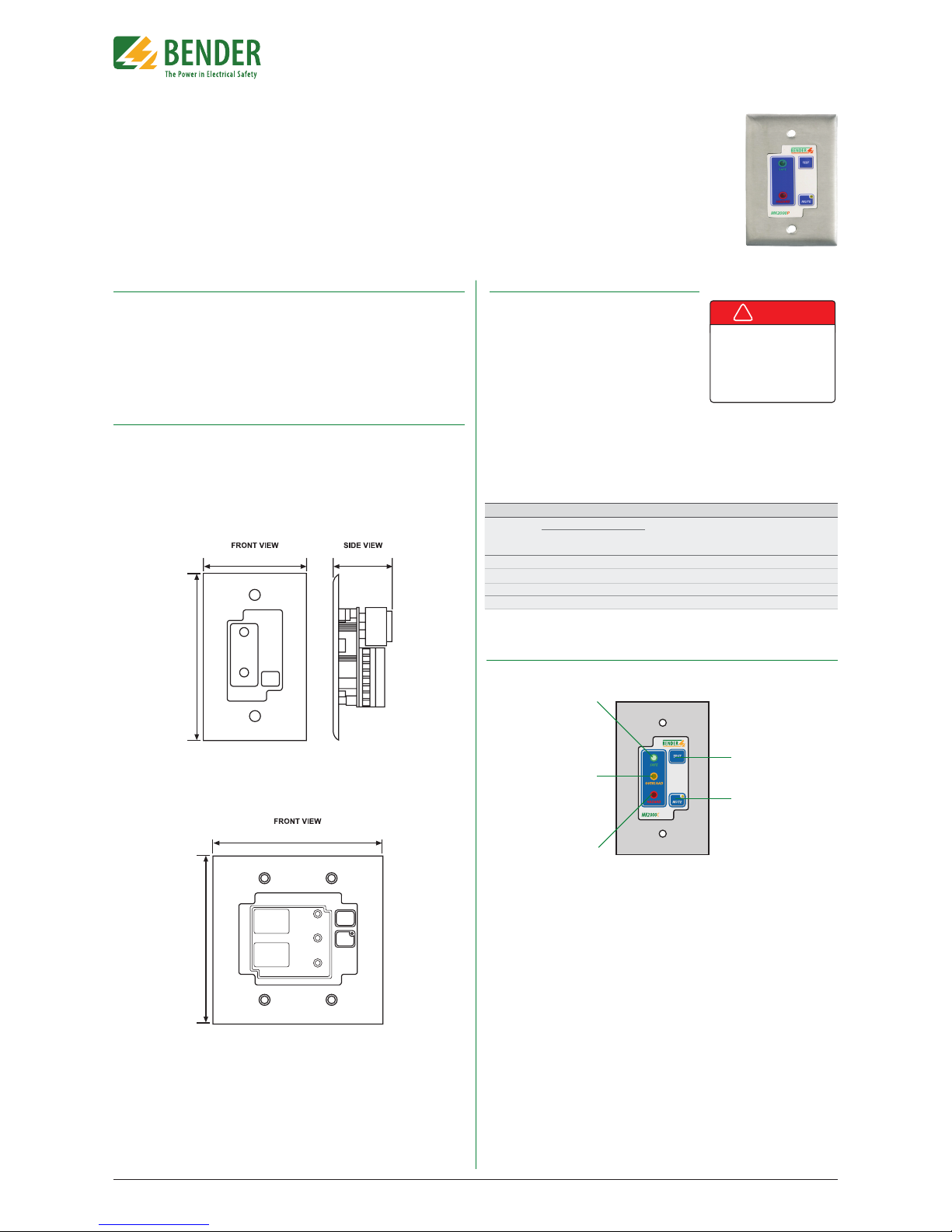
Mounting
Single-gang plates provide two holes at the top and bottom for screw mounting. Two-gang
plates provide four holes (Two at the top, two at the bottom) for screw mounting. Use the provided screws for mounting. MK2000 series remotes utilize standard size gang plates. Refer to
Figure 1 for single-gang plates, and Figure 2 for two-gang plates.
Front Panel Display (Example: MK2000CP-G1)
NOTE: Depending on the type of remote, not all features shown in the image below may be
available. Consult the list below or the manufacturer for more details.
1. Green “SAFE” LED. Illuminates when the
connected LIM2010 is in the normal
condition.
2. Amber “OVERLOAD” LED (Only available with MK2000C and MK2000CP).
Illuminates when the connected
LIM2010’s transformer overload alarm is
active.
3. Red “HAZARD” LED. Illuminates when
the connected LIM2010 is in the alarm
condition.
4. TEST button (Only available with
MK2000P and MK2000CP). Initiates a
self-test of the connected LIM2010.
5. MUTE button with amber LED. Mutes
the audible alarm when in the alarm
condition. The amber LED indicates that
the audible alarm has been muted.
2.8“ (71.1) 1.6“ (40.6)
4.55“ (115.6)
4.6“ (116.8)
4.55“ (115.6)
Figure 1 - Single-gang wall plate dimensions in inches (mm)
Figure 2 - Two-gang wall plate dimensions in inches (mm)
1
2
3
4
5
Table 1 - Terminal connections for remote muting
LIM2010
Terminal
RI2
MK2000(C)(P)
Effect
Terminal 7 Terminal 8
-- -- -- Only the local device will be muted.
X X -- The LIM2010 mute button will mute both devices.
X -- X The MK2000 mute button will mute both devices.
X X X Both mute buttons will mute both devices.
Figure 3 - MK2000CP-G1 diagram
Applicable Devices
This document applies to the following remote indicators:
• MK2000 ( - G1 / G2) Mute
• MK2000P (- G1 / G2) Mute, test
• MK2000C (- G1 / G2) Mute, overload
• MK2000CP ( - G1 / G2) Mute, test, overload
For MK2000CBM remote indicators, refer to document NAE2028450 for installation instructions. For all other remote types, refer to the respective user manual for installation instructions.
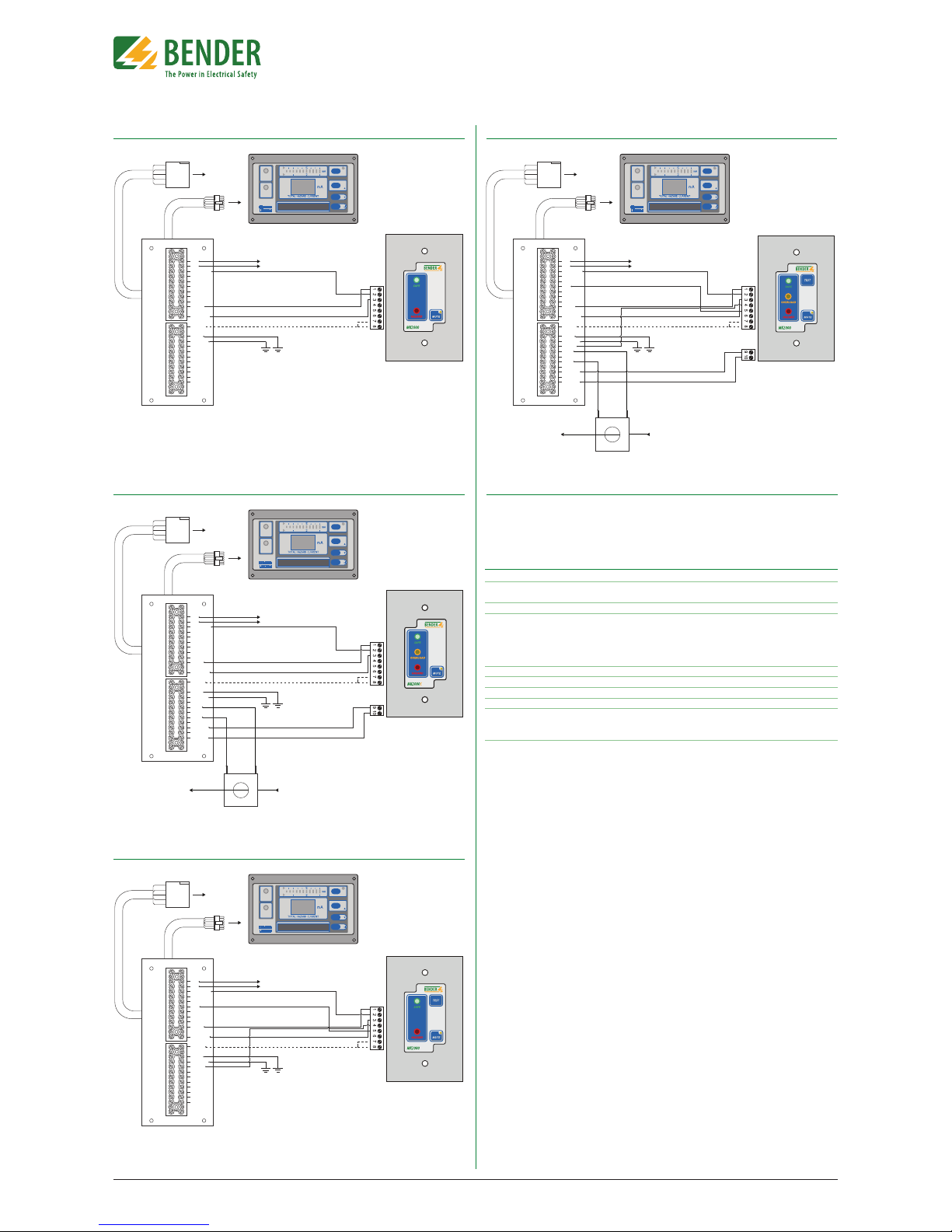
Wiring
MK2000 series remotes connect to a connector plate assembly, which is connected to the LIM2010 Line Isolation Monitor. Ensure that the LIM2010 and corresponding connector plate have already been installed.
Locate the wiring diagram for the correct MK2000
series remote on the reverse side of this document.
For more information on the connector plate and installation, refer to the LIM2010 User Manual, document
NAE2025010.
Wiring - Remote Muting
Remote indicators that do not have bus capability may be muted collectively by connecting
terminals 7 and 8 on the remote to terminal RI2 on the LIM2010. No matter how the wiring
is congured, each respective device is able to mute itself. Wiring between the remote and
the LIM2010 will aect whether a particular device will mute more than itself. Refer to Table
1 below for details.
!
DANGER
• Disconnect all power before servicing.
• Reference NFPA 99 / CSA Z32 for
Installation Standard.
HAZARD OF ELECTRIC SHOCK,
EXPLOSION, OR ARC FLASH
Page 2
T M
Document NAE2028520 • 08.2015 • © Bender Inc. • Page 1/1 • Side 2/2Bender Inc. • USA: 800.356.4266 / 610.383.9200 / medical@bender.org • Canada: 800.243.2438 / 905.602.9990 / info@bender-ca.com • www.bender.org
MK2000(C)(P) Series
Installation Bulletin / Reference Guide
Figure 4 - Wiring, MK2000
Figure 5 - Wiring, MK2000C
Figure 6 - Wiring, MK2000P
Figure 7 - Wiring, MK2000CP
Technical Data
Operating voltage 12V DC or 12V AC
Max. current 50 mA
(MK2000CBM 100 mA)
Operation class continuous operation
Ambient temperature
when operating +32º F to +122º F
0º C to +50º
when stored -13º F to +158º F
-25º C to +70º C
Connection screw terminal block
Conductor size AWG 30…12
Tightening torque 5…7 lb-in.
Mounting by screws
Weight
MK2000-G1 / MK2000P-G1 / MK2000C-G1 / MK2000CP-G1 0.25 lb
MK2000-G2 / MK2000CBM 0.32 lb
CP-LIM2010
Connector Plate
To
load center
SAFE
HAZARD
MUTE
ESC
TEST
RESET
MENU
LIM2010
To panel
ground
MK2000
L1
L2
12VDC CM
A
B
RI1
K1/NC
K1/COM
K1/NO
SAFE
HAZARD
RI2
LIMGND
TEST
1S1
Z1/M+
1S2
Z2/MK2/COM
K2/NC
K2/NO
GND2
CP-LIM2010
Connector Plate
To
load center
SAFE
HAZARD
MUTE
ESC
TEST
RESET
MENU
LIM2010
To panel
ground
MK2000C
STW3 / STW4
L1 from
transformer
secondary
L1 to
load center
L1
L2
12VDC CM
A
B
RI1
K1/NC
K1/COM
K1/NO
SAFE
HAZARD
RI2
LIMGND
TEST
1S1
Z1/M+
1S2
Z2/MK2/COM
K2/NC
K2/NO
GND2
CP-LIM2010
Connector Plate
To
load center
SAFE
HAZARD
MUTE
ESC
TEST
RESET
MENU
LIM2010
To panel
ground
MK2000P
L1
L2
12VDC CM
A
B
RI1
K1/NC
K1/COM
K1/NO
SAFE
HAZARD
RI2
LIMGND
TEST
1S1
Z1/M+
1S2
Z2/MK2/COM
K2/NC
K2/NO
GND2
CP-LIM2010
Connector Plate
To
load center
SAFE
HAZARD
MUTE
ESC
TEST
RESET
MENU
LIM2010
To panel
ground
MK2000CP
STW3 / STW4
L1 from
transformer
secondary
L1 to
load center
L1
L2
12VDC CM
A
B
RI1
K1/NC
K1/COM
K1/NO
SAFE
HAZARD
RI2
LIMGND
TEST
1S1
Z1/M+
1S2
Z2/MK2/COM
K2/NC
K2/NO
GND2
Figure 8 - Wiring, MK2000CBM
Refer to MK2000CBM installation bulletin, document NAE2028450 for instructions and wiring
diagram for installing an MK2000CBM remote indicator.
 Loading...