

Bender MEDICS UMC107E-25, MEDICS UMC107E-40, MEDICS UMC107E-65, MEDICS UMC107E-80 Operating Manual
Page 1
Operating Manual
Power in electrical safety
MEDICS® UMC107E-..
Two-pole
changeover and monitoring modules
for medical locations
TGH1322en/06.2009
Page 2

Dipl.-Ing. W. Bender GmbH & Co.KG
Londorfer Str. 65 • 35305 Grünberg • Germany
Postfach 1161 • 35301 Grünberg • Germany
Tel.: +49 6401 807-0
Fax: +49 6401 807-259
E-mail: info@bender-de.com
Web: http://www.bender-de.com
© Dipl.-Ing. W. Bender GmbH & Co.KG
All rights reserved.
Reprinting only with permission
of the publisher.
Subject to change!
Page 3

Table of Contents
1. How to use this operating manual effectively ................................................... 5
1.1 How to use this manual ......................................................................................................... 5
1.2 Explanations of symbols and notes ................................................................................... 5
2. Safety instructions .................................................................................................. 7
2.1 Intended use .............................................................................................................................. 7
2.2 Skilled persons .......................................................................................................................... 7
2.3 Device-specific safety information .................................................................................... 8
2.4 General safety instructions ................................................................................................... 8
2.5 Delivery conditions, guarantee, warranty and liability .............................................. 8
3. System description ................................................................................................. 9
3.1 MEDICS® ...................................................................................................................................... 9
3.2 UMC107E.. features .............................................................................................................. 10
3.3 Functionality UMC107E-.. ................................................................................................... 11
3.3.1 The UMC107E-... changeover and monitoring module .......................................... 11
3.3.2 IT system monitoring ........................................................................................................... 11
3.3.3 Monitoring the device functions ..................................................................................... 12
3.3.4 Power supply .......................................................................................................................... 12
3.4 System components ............................................................................................................12
3.5 Front view UMC107E-.. .......................................................................................................13
3.6 UMC107E-.. design plan ...................................................................................................... 14
4. Installation and connection ............................................................................... 15
4.1 Fuses .......................................................................................................................................... 15
4.1.1 Selecting a fuse with only one load ............................................................................... 15
4.1.2 Selecting a fuse with several loads ................................................................................. 16
4.2 Changeover and monitoring module ........................................................................... 17
4.2.1 Typical connection ............................................................................................................... 17
4.2.2 Wiring diagram ...................................................................................................................... 18
4.2.3 Circuit diagram ...................................................................................................................... 19
4.3 Instructions for connection ............................................................................................... 20
4.3.1 Temperature sensor ............................................................................................................. 20
4.3.2 Alarm indicator and test combination .......................................................................... 20
TGH1322en/06.2009
3
Page 4

Table of Contents
4.3.3 SCADA system (Supervisory Control And Data Acquisition) ................................. 20
5. Commissioning, settings and testing ............................................................... 21
5.1 Setting and testing according to the checklist ........................................................... 21
5.1.1 Avoiding errors ....................................................................................................................... 21
5.2 Assigning addresses-examples ........................................................................................ 22
6. Trouble shooting .................................................................................................. 23
6.1 PRC487 error messages ....................................................................................................... 23
6.2 Fuses F1...F11 ........................................................................................................................... 24
7. Periodic verification and service ....................................................................... 25
7.1 Periodic verification .............................................................................................................. 25
7.1.1 Testing the changeover module ...................................................................................... 26
7.2 Service ........................................................................................................................................ 26
7.3 Maintenance ............................................................................................................................ 26
8. Data ......................................................................................................................... 27
8.1 TÜV-test report ....................................................................................................................... 27
8.2 Standards .................................................................................................................................. 28
8.3 Manufacturer's certificate ...................................................................................................28
8.4 Technical data ......................................................................................................................... 28
8.4.1 Dimension and weights ......................................................................................................30
8.5 Ordering information ........................................................................................................... 30
9. Manufacturer's certificate, checklist, circuit documentation ..................... 31
4
TGH1322en/06.2009
Page 5
How to use this operating manual effectively
1. How to use this operating manual effectively
1.1 How to use this manual
This operating manual describes how to operate the UMC107E-... changeover and monitoring
module. It is designed for skilled persons working in electrical engineering and electronics;
and in particular for those designing, installing and operating electrical equipment in the
medical sector.
Before using the equipment, please read this operating manual, the supplement entitled "Important safety instructions for Bender Products" and the instruction leaflets supplied with the
individual system components. This document must be kept in an easily accessible location
near to the equipment.
Should you have any further questions, please contact our Technical Sales Department. We
are also happy to provide on-site service. Please contact our Service Department for more
information.
In this manual, the two redundant supplies for the power supply will be designated "preferred supply" or "line 1" and "second supply" or "line 2". Devices with displays use the terms
"line 1" and "line 2" in the text they indicate.
This manual has been compiled with great care. Nevertheless errors and omissions cannot
be entirely excluded. The Bender Group cannot accept any liability for injury to persons or
damage to property resulting from errors or mistakes in this operating manual.
1.2 Explanations of symbols and notes
The following terms and symbols are used to denote hazards and instructions in Bender documentation:
This symbol indicates an immediate risk to life and limb.
Failure to observe the associated instructions and take appropriate precautions
will result in death, severe bodily injury or substantial damage to property.
Danger!
This symbol indicates a potential risk to life and limb.
Failure to observe these warnings and take appropriate precautions may result
in death, severe bodily injury or substantial damage to property.
Warning
This symbol indicates a potentially dangerous situation.
Failure to observe the associated instructions and take appropriate precautions
may result in minor bodily injury or damage to property.
Caution
TGH1322en/06.2009
5
Page 6

How to use this operating manual effectively
This symbol indicates important information about the correct use of the equipment purchased.
Failure to observe the associated instructions can result in equipment malfunctioning or cause problems in the environment in which it is being used.
This symbol indicates tips for using the equipment and particularly useful information. This type of information will help you to optimise your use of the equipment.
6
TGH1322en/06.2009
Page 7

Safety instructions
2. Safety instructions
2.1 Intended use
The UMC107E-.. changeover and monitoring module is a two-pole, automatic changeover
module for distribution systems used in medical locations group 1 and 2, in accordance with
IEC 60364-7 710: 2002-11, section 710.313.1 and DIN VDE 0100-710 (VDE 0100 Part
710):2002-11, section 710.537.6.2 extended by the IT system monitoring functions in accordance with IEC 60364-7-710:2002-11, section 710.413.1.5 and DIN VDE 0100-710 (VDE 0100
part 710):2002-11, section 710.531.3.1.
It is used in medical locations and monitors the power supply using two independent singlephase supply sources and the AC IT system.
The UMC107E-.. module
z detects whether the preferred supply has failed and automatically performs a two-pole
changeover to the second supply source.
z monitors the insulation resistance in the downstream IT system.
z monitors the load current and temperature of isolating transformers for the IT system.
Customised parameter settings must be made on the equipment for the purpose of adapting
it to local equipment and operating conditions, in order to meet the requirements of applicable standards.
The equipment can also be used in non-medical areas provided that the intended application
has been cleared with Bender in advance.
Please note the limits of the area of application indicated in the technical data.
Use deviating from or beyond the scope of this is considered non-compliant.
Intended use also implies:
z Device-specific settings in accordance with IEC 60364-7-710:2002-11, sections 556.5.2.2, 556.7,
556.8 and DIN VDE 0100-710 (VDE 0100 Part 710):2002-11, section 710.537.6.2 (changeover
periods) and for the IT system.
z The observation of all information in the operating manual.
z Compliance with test intervals.
2.2 Skilled persons
Only electrically skilled persons may work on Bender products. Skilled means, persons who
are familiar with the assembly, commissioning and operation of the equipment and have undergone appropriate training. Such persons must have read this manual and understood all
instructions relating to safety.
TGH1322en/06.2009
7
Page 8

Safety instructions
2.3 Device-specific safety information
Device-specific settings are required in order to adapt the MEDICS® module to
the existing equipment. To this end, refer to the instructions in chapter "5. Commissioning, settings and testing", page 21ff.
Warning
2.4 General safety instructions
Bender equipment is designed and built in accordance with the state of the art and accepted
rules in respect of technical safety. However, the use of such devices may introduce risks to
the life and limb of the user or third parties and/or result in damage to Bender equipment
or other property.
z Only use Bender equipment:
–as intended
– in perfect working order
– in compliance with the accident prevention regulations and guidelines applicable in the
location of use
z Rectify any faults that may impair safety immediately.
z Do not make any unauthorised changes and only use replacement parts and optional accesso-
ries purchased from or recommended by the manufacturer of the equipment. Failure to
observe this requirement can result in fire, electric shock and injury.
z Reference plates must always be clearly legible. Replace damaged or illegible plates immedi-
ately.
z Make sure that the dimensioning of the UPS (special safety power supply source), the generator
system and the whole wiring is adequate. Observe the applicable national and international
standards within this context. Only in this way, selective operation of safety devices can be
achieved and a high degree of safety in case of overload and short circuit can be ensured.
2. 1 Delivery conditions, guarantee, warranty and liability
The conditions of sale and delivery set out by Bender shall apply.
Conditions of sale and delivery can be obtained from Bender in printed and electronic format.
8
TGH1322en/06.2009
Page 9
System description
3. System description
3.1 MEDICS
The UMC107E-.. changeover and monitoring module is a part of the MEDICS® system.
MEDICS
supplies in medical locations.
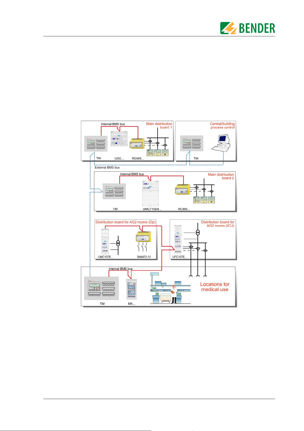
Example of a section of a hospital with the MEDICS®system
®
does not refer to a single product, but rather an intelligent system for safe power
®
Key for example
MK... Alarm indicator and test combination
RCMS... Residual current monitoring system for TN-S systems
SMI472 Signal converter for third-party technical equipment (e.g. med. gases, UPS)
TM Alarm indicator and operator panel
UFC107E... Changeover and monitoring module for IT systems with EDS... insulation fault
UMC107E... Changeover and monitoring module for IT systems
UMC710D... Changeover module for main distribution boards
USC710D... Control module for changeover modules (preferably in main distribution
TGH1322en/06.2009
location system
boards)
9
Page 10

System description
MEDICS® includes:
z AC and 3(N)AC changeover and monitoring modules. Examples of modules in the MEDICS
®
sys-
tem include UMC..., USC..., UFC... and EDS.... insulation fault location systems.
z Display and operating units such as alarm indicator and operator panels or alarm indicator and
test combinations.
z Communication between these components takes place via the BMS bus (two-wire connec-
tion).
z The connection of third-party technical equipment by means of protocol converters (gate-
ways), via digital inputs and relay outputs.
The real strength of MEDICS
®
is to be found in communication between all involved components and the resulting information provided to the user. Readiness for operation is monitored continuously. Operating states, irregularities, faults and equipment failures are
displayed. From the user's point of view, this means high operational reliability.
3.2 UMC107E.. features
The UMC107E-.. changeover and monitoring module has the following features:
z Two-pole changeover with contactors. Both contactors have a mechanical latching.
z Voltage monitoring on the preferred supply (line 1)
z Voltage monitoring on the second supply (line 2)
z Voltage monitoring at the output of the changeover and monitoring module (line 3)
z Monitoring of the switching elements to ensure that they are in the correct switching state and
for wire breaks (connecting wires, contactor coil, coil for latching module)
z Internal functional testing including checking of the changeover times
z Monitoring of the insulation resistance in the IT system
z Monitoring of the IT system transformer load current
z Monitoring of the IT system transformer load temperature
z Monitoring of the A-ISOMETER® 107TD47 connecting wires
z Communication of components with one another via BMS bus
z Communication with remote alarm indicator and test combinations and TM alarm indicator
and operator panels via BMS bus
z Possibility to set the time delay for the changeover in 50 ms increments for adaptation to the
total off-time acc. to DIN VDE 0100-710 (VDE 0100 Part 710):2002-11, section 710.537.6.2k
z Can be used in systems in accordance with IEC 60364-7-710:2002-11, sections 556.5.2.2, 556.7
and 556.8 and DIN VDE 0100-710 (VDE 0100 Part 710):2002-11, section 710.564.6 with a changeover period = 15 s or = 0.5 s
Warning
10
®
The MEDICS
module is a configured unit and is only certified and tested in this
assembly. Do not make any changes to the components, their password-protected settings or the wiring without consulting Bender first.
In each case you shou ld ma ke th e sett ings that are required for adaptation to the
application case in question and local conditions.
TGH1322en/06.2009
Page 11

System description
3.3 Functionality UMC107E-..
3.3.1 The UMC107E-... changeover and monitoring module
If the preferred supply should fail, the UMC107E-.. ensures safe changeover of the
power supply:
1. In normal condition (fault-free condition), the preferred supply (line 1) is connected via contactor K1 and mechanically latched. This makes it impossible for the IT supply to fail on account of
defective contactor coils, torn lines to the contactor coil, or a failure of the control voltage.
2. If the voltage at the end of the preferred supply falls below the set value or exceeds a value of
115 % x U
response time t(off) has elapsed, K1 is disconnected and, following the set idle time t(K1-2), K2
is connected and latched.
3. On voltage recovery, switching back to the preferred supply source occurs automatically after
the set return transfer time t(on) has elapsed: K2 is disconnected and, following the set idle
time t(K1-2), K1 is connected and latched.
Warning
, the module automatically changes over to the second supply (line 2): Once the set
n
The response time t(off), the idle time t(K1-2) and the return transfer time t(on) of
the UMC107E-.. can be set and must be adjusted according to the requirements
of the specific application case, the short-circuit calculation and the requirements of IEC 60364-7-710:2002-11, sections 556.5.2.2, 556.7 and 556.8 and DIN
VDE 0100-710 (VDE 0100 Part 710):2002-11, section 710.537.6 (automatic
changeover modules) (see chapter 5. "Commissioning, settings and testing").
The settings made at the factory ensure a changeover period of t = 0.5 seconds and switching
back within five seconds on voltage recovery on the preferred supply. Therefore, the
UMC107E-.. can also be used in IT systems with a requirement for a changeover period t =
0.5 seconds (IT systems with operating theatre lighting circuits, endoscopic field illumination
in operating theatres, or other essential sources of light, etc.).
If the control device detects a supply line failure or a fault, a message appears in the LC display, the "ALARM" LED lights up, the alarm relay switches, and this alarm is transmitted to
other Bender devices (such as alarm indicator and test combinations) via the BMS bus.
3.3.2 IT system monitoring
Insulation monitoring
The insulation monitoring device measures the insulation resistance in AC IT systems which
may also contain DC circuits. The adaptation to the system leakage capacitances takes place
automatically.
Load current measurement
The load current is measured via the measuring current transformer STW2.
Temperature measurement
The temperature in the transformer winding is measured via PTC thermistors.
Evaluation
If any of the measured values does not fall within the limits, an alarm (common alarm) is
triggered. The "ALARM" LED lights up, the alarm relay switches and a message appears in
the LC display of the insulation monitoring device. This alarm is transmitted to other Bender
devices (such as an alarm indicator and test combination) via the BMS bus.
TGH1322en/06.2009
11
Page 12

System description
3.3.3 Monitoring the device functions
The control circuits are constructed in such a way that even if a particular fault will almost
certainly occur, it cannot cause the power supply at the output of the automatic changeover
and monitoring module to fail. Examples: Failure of the control voltage, operation of a protective device, a short-circuit to exposed-conductive part or an earth fault, and an open circuit.
In addition to this, the module continuously monitors:
z The control circuit that is required for the next changeover process (coil, control contacts, con-
nections)
z Important connecting wires, such as
– the insulation monitoring mains/PE
– measuring current transformer
– temperature sensor
z For alarm indicator and test combinations, and alarm indicator and operator panels, device fail-
ure monitoring can also be programmed via the BMS bus.
Thanks to the redundant hardware design of the changeover module, it is guaranteed to
function safely even if the microcontroller should fail.
3.3.4 Power supply
SUE487 provides the power supply for the PRC487 control device and the AN450 power supply unit, as well as the control voltage for the contactors from line 2, (or from line 1 if line
2 fails). The 107TD47 insulation monitoring device is supplied by the IT system.
The AN450 power supply unit supplies power to a maximum of 3 MK2418 or 2 MK2430
alarm indicator and test combinations.
3.4 System components
In chapter "9. Manufacturer's certificate, checklist, circuit documentation" of this operating
manual, you will find instruction leaflets containing detailed information about the following
system components:
PRC487 Control device for changeover modules
SUE487, SUD487 Voltage relay
A-ISOMETER®107TD47 Insulation monitoring device with transformer
monitoring
BMS bus Bender Measuring Device Interface
AN450 Power supply unit
STW2 Measuring current transformer
12
TGH1322en/06.2009
Page 13
System description
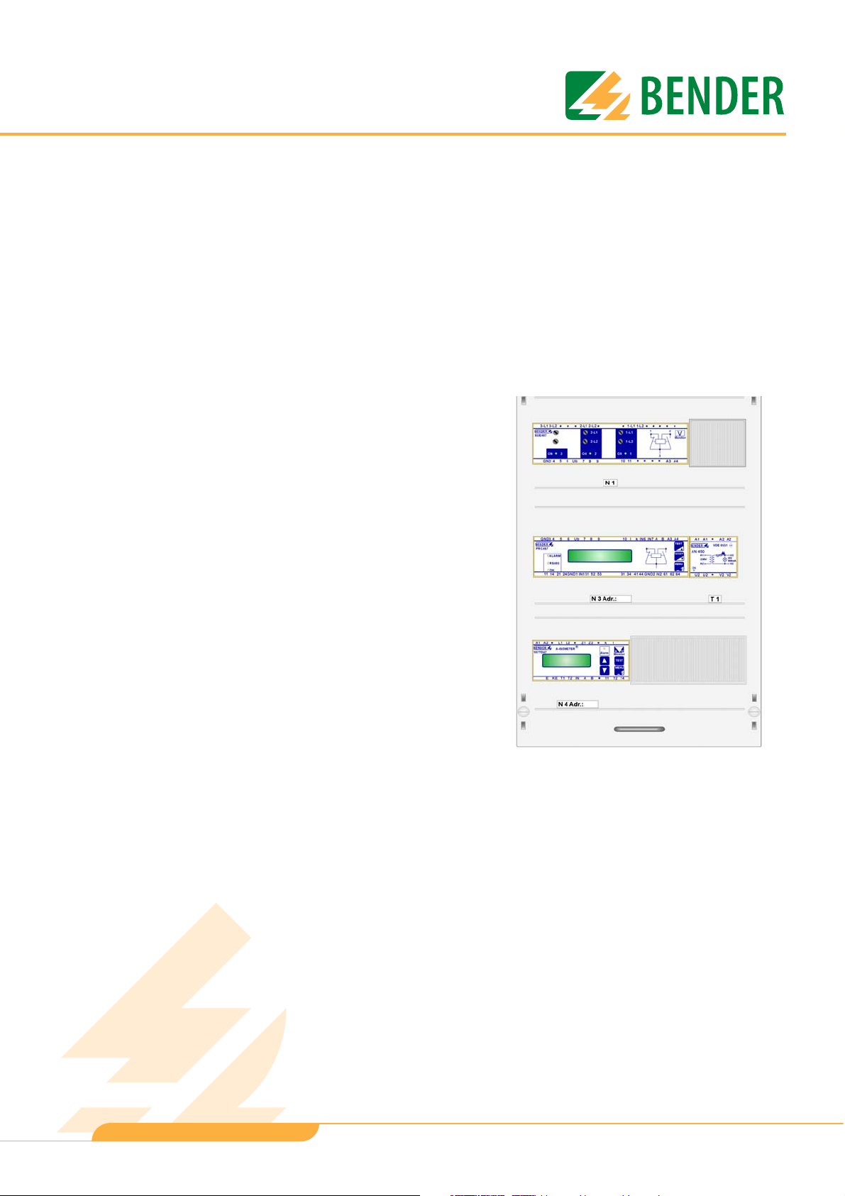
3.5 Front view UMC107E-..
Terminal compartment
Contactor with latching module
SUE487 voltage monitoring device
Control device PRC487
Power supply unit AN450
107TD47 A-ISOMETER® to monitor the insulation resistance, as well as transformer load
and temperature
Example: UMC107E-... front view on a Striebel & John equipment rack.
TGH1322en/06.2009
13
Page 14
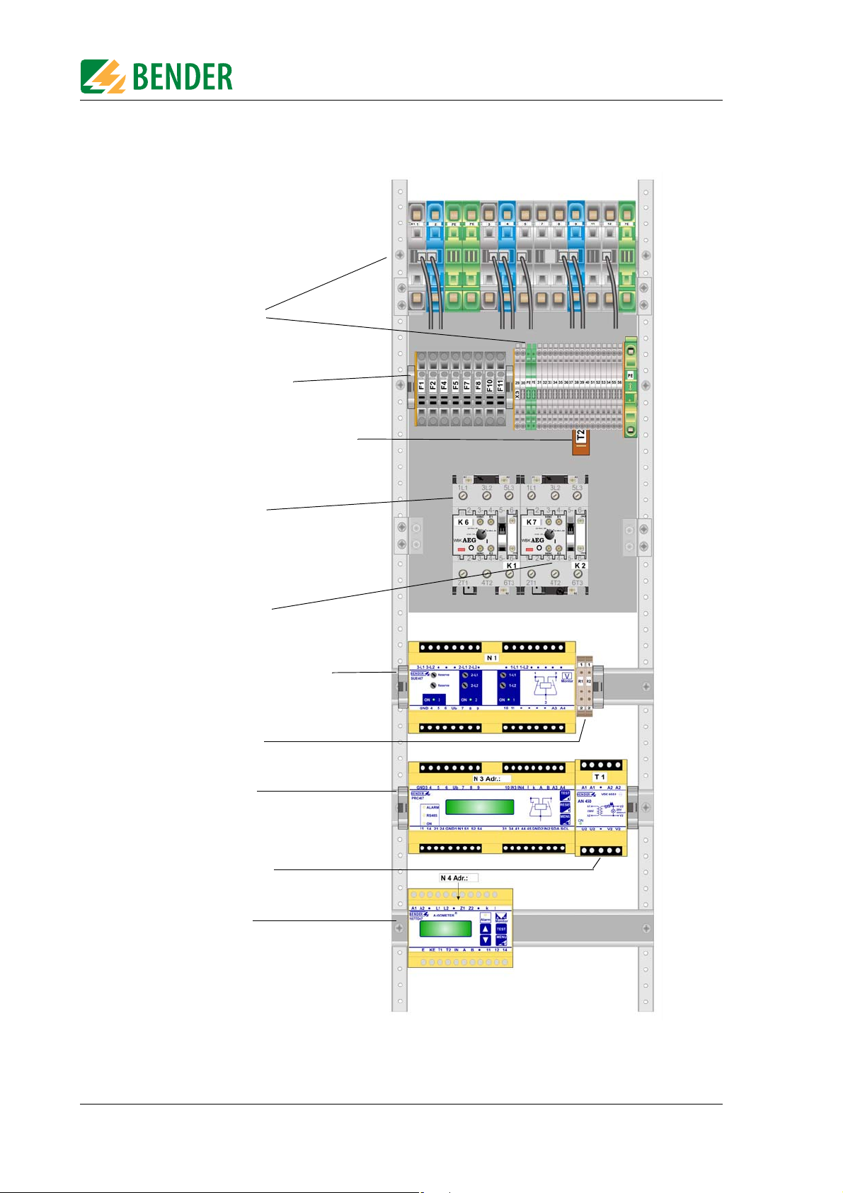
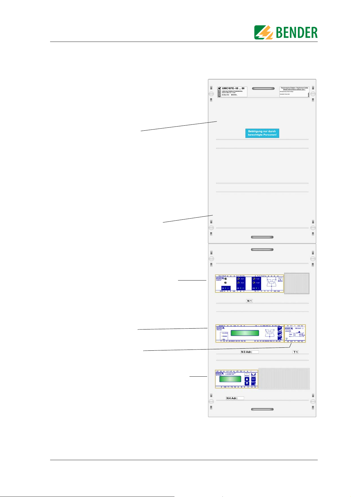
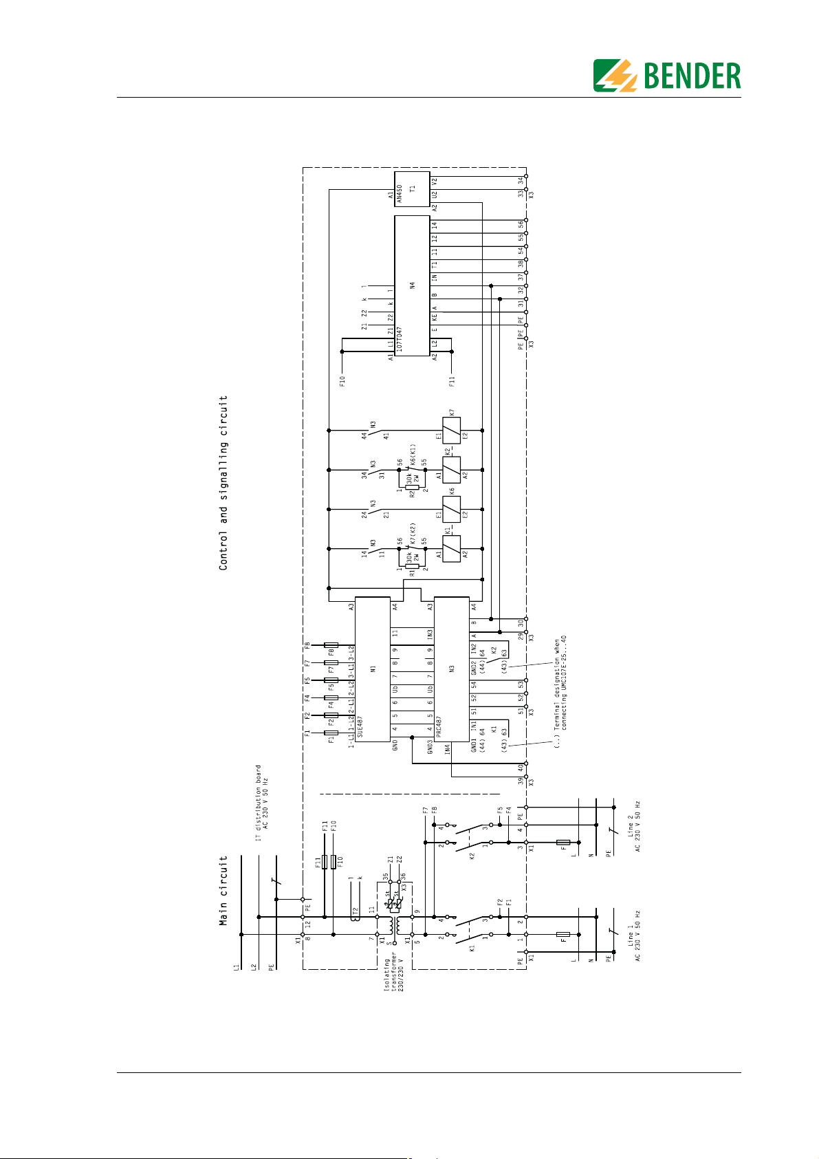
3.6 UMC107E-.. design plan
X1, X2, X3: Terminal strips
F1...F11: Fuses see "chapter 6.2"
T2: STW2 measuring current transformer for
load current measurement
System description
K1: Contactor for line 1 with
K6: latching module
K2: Contactor for line 2 with
K7: latching module
N1: SUE487 voltage monitoring device
R1, R2: Resistors 30 kΩ, 2 W
N3: Control device PRC487
T1: Power supply unit AN450
N4: A-ISOMETER®107TD47
Example: Design plan UMC107E-... on a Striebel & John equipment rack.
14
TGH1322en/06.2009
Page 15
Installation and connection
4. Installation and connection
4.1 Fuses
Please observe the requirements of IEC 60364-7-710:2002-11 and DIN VDE 0100-710 (VDE
0100 Part 710) when selecting fuses for the supply cables and outgoing circuits of the
changeover modules:
z Section: 710.512.1.6.2 (VDE), sections 710.5.3.1, 710.512.1.6 (IEC), Transformers for the IT system:
Where transformers, their primary supply conductor and secondary outgoing line are concerned, overcurrent protective devices are only permitted for short-circuit protection. The
transformer supply cable from the changeover module and the transformer outgoing cable to
the next distribution board section should be laid so that they are short-circuit proof and earthfault proof.
z Section: 710.53.2 (VDE), section 710.413.1 (IEC), Protection of the cable system in Group 2 loca-
tions: The choice of protective devices must ensure that when the anticipated short-circuit current occur, the protective device upstream of a fault will selectively trip the protective devices
that are further upstream.
z Section 710.537.6.2. (VDE), section 710.413.1.1 (IEC), Connecting several load groups down-
stream of a changeover module must not lead to all the load groups failing in the event of a
fault.
As a result, the choice of fuses F should ensure both short-circuit protection for the transformer and selectivity for the overcurrent devices connected downstream in the IT systems.
When selecting fuses, please observe both the maximum permissible values laid down by
the guidelines that apply to the location of use and national and international standards, in
order to ensure that the contactor contacts cannot weld. The considerations presented below
are based on the standard DIN VDE 0100-710 (VDE 0100 Part 710): 2002-11, section
710.537.6.
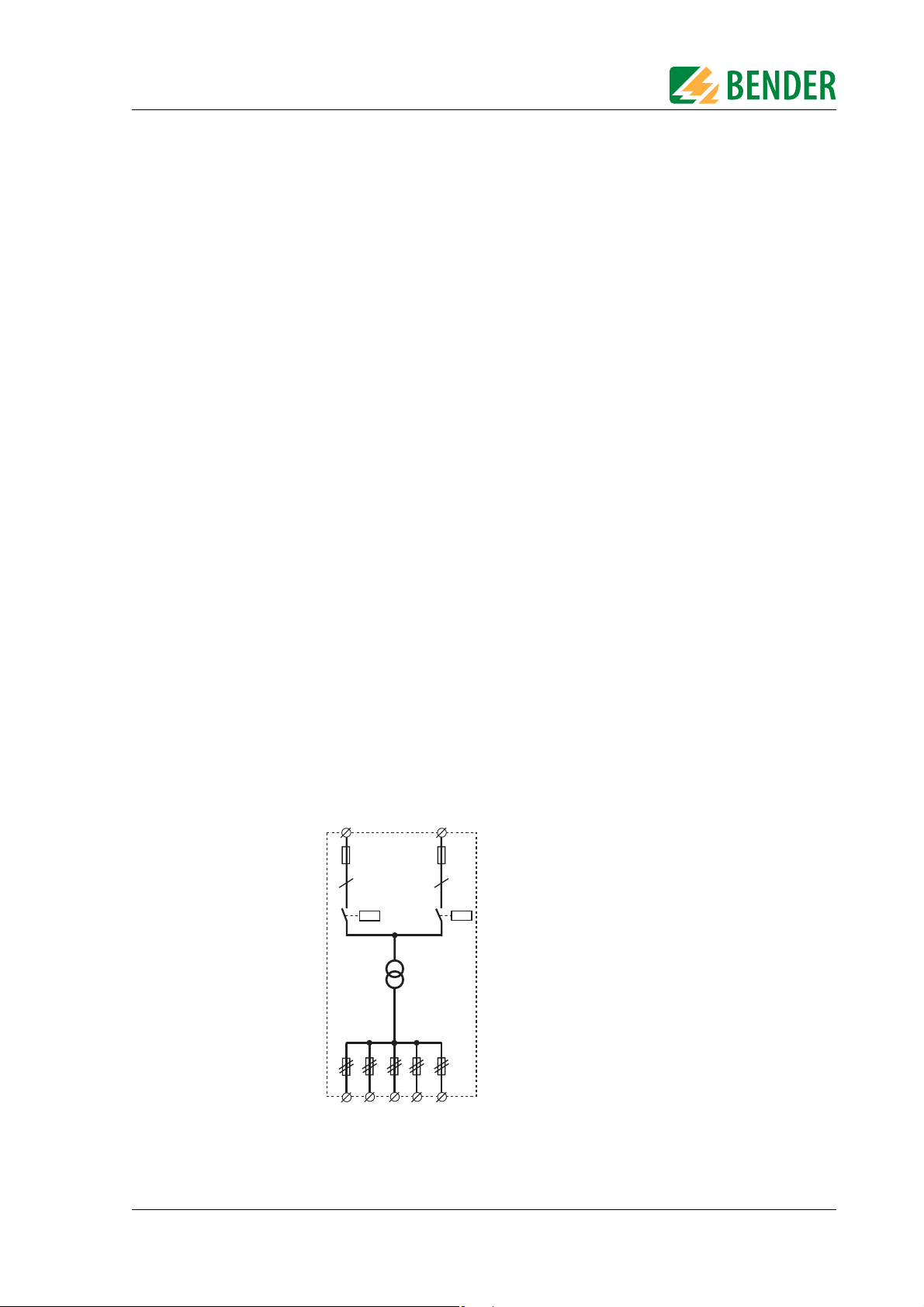
4.1.1 Selecting a fuse with only one load
F1 F2
2
2
Changeover module
Contactors with latching
TGH1322en/06.2009
Circuit breaker
15
Page 16
Installation and connection
The circuit only has one load: the IT system transformer. Taking into consideration the explanation in section 710.537.6 as well as the manufacturer's technical data for the contactor,
the maximum possible fuse (F1 or F2) for the contactor can be calculated as follows:
= Manufacturer's technical data regarding max. fuse x 0.45
I
v
The fuse must match the fuse specified by the manufacturer of the selected IT system transformer.
The rated operational current I
= Manufacturer's technical data for the switching contact with consideration of
I
e
of the changeover module is calculated as follows:
e
AC-3 conditions x 0.45
This rated operational current must be greater than the rated operational current of the IT
system transformer.
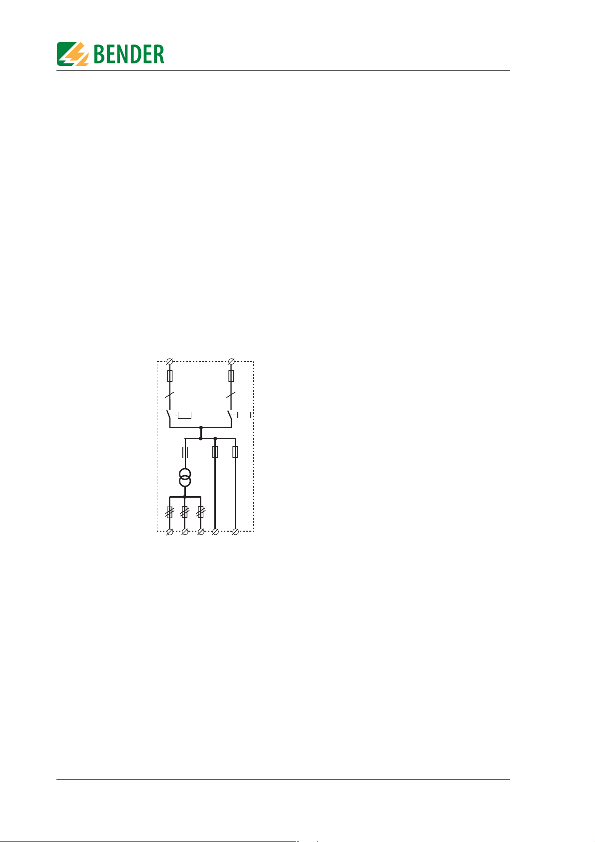
4.1.2 Selecting a fuse with several loads
F1 F2
2
F3 F4
2
Changeover module
Contactors with latching
F5
Circuit breaker
This circuit branches into several load groups. The result is that every fuse of every load
group is moved downstream of the changeover module. Regardless of this, the maximum
possible fuse is calculated in the same way as described above.
The rating of this fuse (F1 or F2) must be coordinated with the rating of fuse F3 (and of
course F4 and F5) so that selective shutdown is ensured. The fuse specified by the manufacturer for the IT system transformer must therefore be at least two stages smaller in rating
than the fuse calculated using the formula above for the changeover module. Of course, the
total nominal current for the changeover module must be calculated from the sum and simultaneity factor of all load groups connected, and the required or minimum rated current calculated according to the formula above.
The values listed in the ordering information apply for the changeover modules.
16
TGH1322en/06.2009
Page 17

Installation and connection
4.2 Changeover and monitoring module
The power supply of Group 2 location is supplied via an isolating transformer. For protection
against indirect contact, one of the following measures is to be used for the transformer:
z Protective insulation according to DIN VDE 0100-410 (VDE 0100 Part 410):2007-06, 413.2 (Use of
a protection class II transformer)
z Protection by non-conductive location according to DIN VDE 0100-410 (VDE 0100 Part
410):2007-06, section 413.3
z Protection by a local, earth-free equipotential bonding according to DIN VDE 0100-410 (VDE
0100 Part 410):2007-06, section 413.4
z Protection by special installation. For this measure, please note the following:
– The protection class I transformer must be installed isolated and must not be connected to
the PE conductor. In Bender's ES710 range of transformers, the fixing angles are isolated
from the transformer core.
– A warning label is to be affixed to the transformer and its cover as follows:
Warning! Accessible parts of the transformer may
be live. You must always verify that there is no
voltage present before touching parts of it.
– The transformer is to be installed behind a cover, which can only be opened using a tool or a
special key. It must only be accessed by skilled persons.
– The shield winding can be connected to the PE conductor. It must be ensured that the con-
necting wire is installed so that it is short-circuit proof and earth-fault proof.
4.2.1 Typical connection
Connect your changeover module to the supply sources as follows:
Preferred supply (line 1) Terminals X1:1 and X1:2
Second supply (line 2) Terminals X1:3 and X1:4
z Connect the primary winding of the transformer to the terminals X1:5 and X1:9 and the second-
ary winding to terminals X1:7 and X1:11. A cross section that conforms to DIN VDE 0100 Part
430 must be selected.
TGH1322en/06.2009
17
Page 18
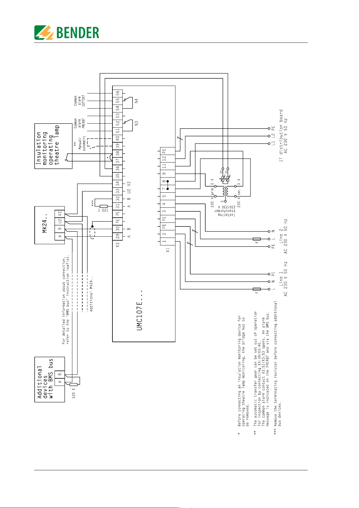
4.2.2 Wiring diagram
Installation and connection
18
Fig. 4.1: Wiring diagram UMC107E-...
TGH1322en/06.2009
Page 19
Installation and connection
4.2.3 Circuit diagram
TGH1322en/06.2009
Fig. 4.2: Circuit diagram UMC107E-...
19
Page 20

Installation and connection
4.3 Instructions for connection
4.3.1 Temperature sensor
Bender IT system transformers are equipped with the temperature sensors required according to their insulation class. These temperature sensors (maximum of 6 sensors connected in
series) are connected to terminals X3:35 and X3:36.
4.3.2 Alarm indicator and test combination
Ex works, the following pairs of terminals are provided for the connection of BMS bus devices:
X3:29 and X3:30 (A/B)
X3:31 and X3:32 (A/B terminals are terminated with 120 Ω at the factory)
Alarm indicator and test combinations, panels and other Bender-BMS-bus devices can be
connected.
1. A BMS device or an existing BMS bus with several devices is connected to terminals X3:29 and
X3:30:
The last device at the other end of the bus must be terminated with 120 Ω.
Terminals X3:31 and X3:32 remain terminated.
2. An existing BMS bus that has already been terminated on both ends, is disconnected; one
open branch is connected to terminals X3:29 and X3:30, while the other one is connected to
terminals X3:31 and X3:32:
The 120 Ω resistor, provided ex works, must be removed and the open bus branches must be
connected to the specified terminals.
Please read the information on cable routing in the "BMS bus" instruction leaflet.
The AN450 power supply unit can supply power to a maximum of 3 MK2418 or 2 MK2430
alarm indicator and test combinations via the terminals X3:33 and X3:34. In this respect,
please refer to the documentation for the relevant devices. The AN450 is not suitable for supplying power to TM... operator panels.
4.3.3 SCADA system (Supervisory Control And Data Acquisition)
If messages from the UFC107E-.. changeover and monitoring module are to be transmitted
to a SCADA system, you have the following options:
z Protocol converter (gateways)
z OPC server
z Common alarm via the relay outputs of the 107TD47 A-ISOMETER® and the PRC487 control
device
z Conversion between BMS bus and digital inputs and outputs by means of alarm indicator and
operator panels (TM...) or signal converters (SMO480-12, SMO482-12, SMI 472-12).
20
TGH1322en/06.2009
Page 21

Commissioning, settings and testing
5. Commissioning, settings and testing
5.1 Setting and testing according to the checklist
A total changeover time of t ≤ 0.5 s and switching back within five seconds to the preferred
supply on voltage recovery is factory set.
The response time t(off), the idle time t(K1-2) and the return transfer time t(on) of the
UMC107E-.. can be set and must be adjusted in line with the requirements of the specific
application, the short-circuit calculation and the requirements of IEC 60364-7-710:2002-11,
sections 556.5.2.2, 556.7 and 556.8 and DIN VDE 0100-710 (VDE 0100 Part 710):2002-11, section 710.537.6 (automatic changeover modules).
z The total off time permitted to occur (from the point at which the fault occurs until the arc in
the overcurrent protective device is cleared) must be less than the minimum time delay for the
changeover process of the automatic changeover module. Setting: Response time t(off)
z If several changeover modules are connected in series in a power supply system, it is recom-
mended that they be time-graded. Setting: Response time t(off), idle time t(K1-2) and return
transfer time t(on).
z As part of the response delay (to be custom-set), you must, at the very least, take into account
the periods of time when the circuit experiences short interruptions, and the response times of
the short-circuit protective device connected upstream or downstream. Regardless of this, the
idle time for the changeover process corresponding to the place of installation must be considered to prevent switching overvoltages.
Setting: Response time t(off) and idle time t(K1-2).
For this purpose, please consult the changeover time lapse diagram in the instruction leaflet
for the PRC487 control device and make the settings required according to the description.
You will find a checklist in chapter "9. Manufacturer's certificate, checklist, circuit documentation". This list details the factory settings and the system-specific settings for the MEDICS
module. Please carry out all the work outlined in the list and log each test step.
The checklist contains:
z Visual inspection
z Commissioning, settings, factory settings
z Functional test
Keep this checklist with this manual in a location that is close to the MEDICS
®
module.
5.1.1 Avoiding errors
Communication via the BMS bus can only be guaranteed when there is only one
terminating resistor at the beginning and the end of the BMS bus. Additional terminating resistors can lead to malfunctions and therefore must not be used.
Please also note the information in the "BMS bus" instruction leaflet.
®
TGH1322en/06.2009
21
Page 22
Commissioning, settings and testing
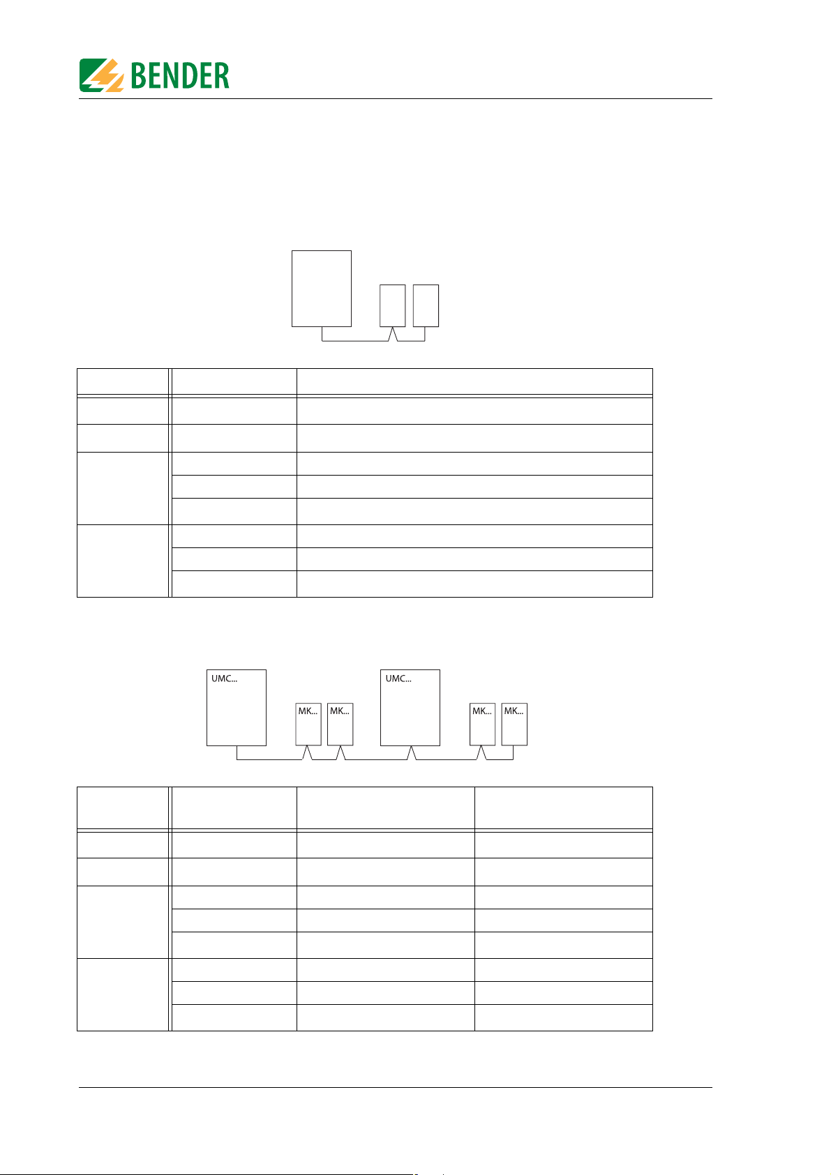
5.2 Assigning addresses-examples
Please also note the information in the "BMS bus" instruction leaflet. * The settings for the
alarm addresses marked with an asterisk (*) refer to reciprocal monitoring of MK... alarm indicator and test combinations.
A changeover and monitoring module with two alarm indicator and test combinations:
UMC...
MK...
MK...
Device Parameters Address settings for a changeover module
107TD47
PRC487
First MK...
Bus address 3
Address 4
Address 1
Test address 3
3, 4, 2
*
Second MK...
Alarm address
Address 2
Test address 3
Alarm address
3, 4, 1
*
Two changeover and monitoring modules, with two alarm indicator and test combinations each:
Device Parameters Address settings for the first
changeover module
Address settings for the
second changeover module
107TD47
PRC487
First MK...
Second MK...
22
Bus address 5 7
Address 6 8
Address 1 3
Test address 5 7
Alarm address
5, 6, 2
*
Address 2 4
Test address 5 7
Alarm address
5, 6, 1
*
7, 8, 4
7, 8, 3
*
*
TGH1322en/06.2009
Page 23

Trouble shooting
6. Trouble shooting
6.1 PRC487 error messages
If a fault occurs, the MEDICS® system messages will enable you to narrow down the possible
causes. Some messages can have several causes. The following possible errors are indicated
by messages in the PRC487 display.
If you cannot trigger a test function on the PRC487, an alarm message may already be pending, or there may be an open circuit at terminal 9-Ub of the PRC487.
PRC message Possible causes
Failure line 1 Power supply failure on line 1. SUE487 failure. Open circuit, ter-
minal 6-GND3. Defective fuse 1-L1, 1-L2.
Failure line 2 Power supply failure on line 2. SUE487 failure. Open circuit, ter-
minal 5-GND3. Defective fuse 2-L1, 2-L2.
Failure distribution
board
Failure K3 Failure of the internal relay K3 (SUD487). Open circuit terminal
K1/2 manual mode Contactor control has been changed to manual mode. Auto-
Short-circuit distribution board
Wire break K1 on Open circuit when controlling K1 via terminals 11/14 of the
Wire break K1 off Open circuit when controlling K1 via terminals 21/24 of the
Wire break K2 on Open-circuit when controlling K2 via terminals 31/34, auxiliary
Wire break K2 off Open circuit when controlling K2 via terminals 41/44 of the
Fault K1 on K1 cannot be activated. K1 is jammed. Open circuit, auxiliary
Fault K1 off K1 cannot be switched off via latching module. K1 is jammed.
Power supply failure downstream of the changeover module.
SUE487 failure. Open circuit terminal 4-GND3
IN3-GND3
matic changeover will no longer be performed!
Short-circuit downstream of changeover module. Following a
failure on line 1 and changeover to line 2, line 2 drops out and
voltage is present on line 1 again.
PRC487, auxiliary contact K2 or resistor R1.
PRC487 for the purpose of shutting down the latching module.
contact K1 or resistor R2.
PRC487 for the purpose of shutting down the latching module.
contact at terminal GND1 or IN1 of PRC487.
Open circuit, auxiliary contact at terminal GND1 or IN1 of
PRC487.
TGH1322en/06.2009
Fault K2 on K2 cannot be activated. K2 is jammed. Open circuit, auxiliary
contact at terminal GND2 or IN2 of PRC487.
Fault K2 off K2 cannot be deactivated via latching module. K2 is jammed.
Open circuit, auxiliary contact at terminal GND2 or IN2 of
PRC487.
Failure K1 K1 on, but no voltage downstream of K1. Open circuit, main
contacts K1 or line upstream or downstream of K1. SUE487 failure.
23
Page 24
PRC message Possible causes
Failure K2 K2 on, but no voltage downstream of K2. Open circuit, main
contacts K2. SUE487 failure. Open circuit terminal 4-GND3.
RS-485 fault Undefined characters on the BMS bus. There is more than one
master in the network. More than one slave has the same
address. Interface (A,B) polarity is incorrect.
No MASTER There is no master. No alarm indicator and test combination or
operator panel connected. Bus line interrupted.
EEPROM fault Defective EEPROM or impermissible value stored in EEPROM.
CV460 fault Settings made in SETUP OPTION menu, even though no CV460
is connected.
RK474 fault Settings carried out in the SETUP OPTION menu, although no
RK474 was connected.
Trouble shooting
You can find additional information on messages in the instruction leaflets for the "PRC487
®
control device" and "107TD47 A-ISOMETER
" in chapter "9. Manufacturer's certificate, check-
list, circuit documentation" of this operating manual.
6.2 Fuses F1...F11
If fuses F1 to F11 are tripped, there may be a defect in the changeover module.
These fuses should only be replaced following consultation with Bender.
Caution
Data for fuses F1 to F11
Tripping current......................................................................................................................................... .......4 A, time lag
Breaking capacity ........................................................................................................................................................ 10 kA
ELU type ................................................................................................................................................................... 189140
Dimensions.....................................................................................................................................................6.25 x 32 mm
24
TGH1322en/06.2009
Page 25

Periodic verification and service
7. Periodic verification and service
7.1 Periodic verification
The following periodic verification must be performed on electrical installations in compliance with the local or national regulations that apply. We recommend for your Bender products:
Test To be
performed by
Functional test of IT system monitoring
(insulation, load current, transformer temperature and connection monitoring) by pressing the TEST button on the alarm
indicator and test combination or on the alarm indicator and
operator panel.
Functional test of the changeover module*:
Test of the automatic changeover modules.
Please observe the information in chapter "Testing the changeover module"!
Functional test of the IT system monitoring (insulation, load
current, transformer temperature and connection monitoring)
on the insulation monitoring device.
Testing the set values and the changeover periods Skilled person every 12
Testing of the changeover module, the IT system monitoring,
the connection to the SCADA system (Supervisory Control And
Data Acquisition) (if applicable) and the interaction of the components in the system.
This test includes the following services:
- Inspection:
Marking, display elements, mechanical components,
wiring, parameterisation, connection of
third-party equipment, evaluation of fault memory
- Measurement:
Internal/external supply voltages/potentials,
bus voltage, bus protocol, bus scan
- Practice test:
Device function, device communication
- Documentation:
Test results, recommendations for remedial action
Medical
personnel
Skilled person every 6 months
Skilled person every 6 months
Bender Service every 24
Interval
once every
working day
months
months
* This test must only be performed by an electrically skilled person who has been commissioned to do
so in agreement with the person responsible for the medical location.
Before carrying out the tests, please refer to the instructions relating to the functional tests
in the checklist. If no national directives apply, you should perform the tests recommended
by IEC 60364-7-710:2002-11, section 710.62 and DIN VDE 0100-710 (VDE 0100 Part
710):2002-11, section 710.62.
TGH1322en/06.2009
25
Page 26

Periodic verification and service
7.1.1 Testing the changeover module
Step Response
Disconnect line 1:
1. Disconnect the fuse switch disconnector or
fuse or
2. Remove fuse F1 or
3. Remove the microfuse on the SUE487/SUD487
Reconnect line 1 1. Changeover to line 1 after delay time t(on).
Disconnect line 2 1. Alarm message "Failure line 2"*
Reconnect line 2 1. Alarm message "Failure line 2"* goes out
1. Changeover to line 2
2. Alarm message "Failure line 1"
3. Message on PRC487: "K1off, K2on"
2. Alarm message "Failure line 1"* goes out
3. Message on PRC487: "K1on, K2off"
Exception:
If an automatic switching back interlocking function is active, the changeover module remains on
line 2 and displays the message "interlocking". To
clear the switching back interlocking function,
interrupt the connection between contacts X3:40
and X3:57.
2. Message on PRC487: "K1on, K2off"
2. Message on PRC487: "K1on, K2off"
TEST on PRC487:
Press the TEST button, RESET button and MENU
button in sequence
To return to the standard display,
press the MENU button
1. Changeover to line 2.
Display: "** TEST **"
2. Changeover to line 1 after t(on).
3. Display of changeover period "t 1->2:
xxxxms" **
Message on PRC487: "K1on, K2off"
* Or corresponding parameterised text. Alarm messages are also transferred via bus or
alarm contacts to TMs, MKs or the building services control system. Test, if necessary.
** Up to a maximum of 15 s; above this no indication possible.
7.2 Service
Bender would be delighted to provide on-site service for commissioning and periodic verification. Please contact our Service Department for more information:
Service-Hotline:
0700-BenderHelp (Telephone and Fax)
Carl-Benz-Straße 10 • 35305 Grünberg • Germany
Tel: +49 6401 807-760 • Fax: +49 6401 807-629
E-Mail: info@bender-service.com • www.bender-de.com
7.3 Maintenance
The MEDICS® module does not contain any parts that require maintenance. Despite this, the
intervals specified for periodic verification should be adhered to.
26
TGH1322en/06.2009
Page 27

Data
8. Data
8.1 TÜV-test report
In 2003, the TÜV Süddeutschland, Bau und Betrieb GmbH, based in Munich, Germany, tested the changeover and monitoring modules in the MEDICS
®
system range.
The complete test report is available at Bender.
TGH1322en/06.2009
27
Page 28

8.2 Standards
The changeover and monitoring module conforms to the following standards:
z DIN VDE 0100-710 (VDE 0100 Part 710): 2002-11
z DIN VDE 0100-725 (VDE 0100 Part 725): 1991-11
z DIN VDE 0100-718 (VDE 0100-718):2005-10
z ÖVE/ÖNORM E8007: 2007-12
z IEC 60364-7-710: 2002-11
z DIN EN 61557-8 (VDE 0413 Part 8):2007-12
z IEC 61557-8:2007-01
z EN 61557-8:2007-07
z DIN EN 60439-1 (VDE 0660 Part 500):2005-01
8.3 Manufacturer's certificate
As part of the scope of supply for the changeover and monitoring module, you will find a
manufacturer's certificate in chapter "9. Manufacturer's certificate, checklist, circuit documentation" of this manual.
Data
8.4 Technical data
Insulation coordination acc. to IEC 60664-1
Rated insulation voltage ........................................................................................................................................AC 250 V
Rated impulse voltage/pollution degree ..................................................................................................................4 kV/3
Voltage ranges
Nominal system voltage U
Nominal frequency f
Supply voltage U
Operating range of U
Frequency range of US......................................................................................................................................... 50...60 Hz
Power section/switching elements
Switching elements ............................................................................................................................... latched contactors
Adjustable changeover period......................................................................................................................... < 0.5... 20 s
Rated operational current I
Rated operational voltage U
Frequency of U
................................................................................................................................................. 50 ... 60 Hz
e
Operating range of U
Voltage monitoring
Adjustable undervoltage response value ......................................................................................................0.7 ... 0.9 x U
Response value overvoltage ..................................................................................................................................1.15 x U
Response time tan........................................................................................................................................... 50 ... 250 ms
Response time t(off) can be set in 50 ms increments.................................................................................... 0 ... 9950 ms
Return transfer time t(on) can be set in 1 s increments ......................................................................................0 ... 249 s
Idle time, can be set in 50 ms increments...................................................................................................... 0 ... 9950 ms
...................................................................................................................................AC 230 V
n
....................................................................................................................................DC, 50...60 Hz
n
...................................................................................................................................................AC 230 V
S
................................................................................................................................... 0.8...1.15 x U
S
..................................................................................................................... see ordering data
e
.................................................................................................................................AC 230 V
e
................................................................................................................................... 0.8...1.15 x Ue
e
S
e
e
28
TGH1322en/06.2009
Page 29

Data
Insulation monitoring
Response value R
, adjustable......................................................................................................................50 ... 500 kΩ
an
Hysteresis................................................................................................................................................................. < 25 %
Response time t
Max. permissible system leakage capacitance C
Measuring voltage U
Measuring current Im max. (where R
Internal DC resistance R
Impedance Z
Max. permissible extraneous DC voltage U
where RF = 0.5 x Ran and Ce = 1 μF ............................................................................................ < 3 s
an
.................................................................................................................................................. 12 V
m
..................................................................................................................................... > 240 kΩ
i
at 50 Hz........................................................................................................................................ > 200 kΩ
i
= 0 Ω).................................................................................................... < 50 μA
F
.................................................................................................... < 5 μF
e
........................................................................................................ DC 375 V
fg
Overload monitoring
Adjustable response value .....................................................................................................................................5 ... 50 A
Hysteresis........................................................................................................................................................................4 %
Temperature influence .................................................................................................................................. < 0.15 % / °C
Overtemperature monitoring
Response value ........................................................................................................................................................... 4 kΩ
Release value ............................................................................................................................................................ 1.6 kΩ
PTC resistors acc. to DIN 44081................................................................................................................... max. 6 in series
Interfaces
Interface/protocol............................................................................................................................................ RS-485/BMS
Connection..................................................................................................................................................... terminals A/B
Max. cable length ............................................................................................................................................... ≤ 1200 m
Recommended cable (shielded, shield connected to PE at one end) ..........................................at least J-Y(St)Y 2 x 0.6
Terminating resistor ................................................................................................................................. 120 Ω (0.25 W)
Switching elements
Switching elements ........................................................................................................................... changeover contacts
Operating principle.......................................................................................................... adjustable N/C or N/O operation
Electrical service life, number of cycles...................................................................................................................... 12000
Rated contact voltage............................................................................................................................AC 250 V/DC 300 V
Making capacity .................................................................................................................................................. AC/DC 5 A
Breaking capacity ....................................................................................................................... 2 A, AC 230 V, cos phi 0.4
.............................................................................................................................................. 0.2 A, DC 220 V, L/R = 0.04 s
General data
EMC immunity ................................................................................................................................. acc. to EN 61000-6-2
EMC emission .................................................................................................................................. acc. to EN 61000-6-4
Shock resistance IEC 60068-2-27 (device in operation).................................................................................. 15 g/11 ms
Bumping IEC 60068-2-29 (during transport) .................................................................................................... 40 g/6 ms
Vibration resistance IEC 60068-2-6 (device in operation)....................................................................... 1 g / 10...150 Hz
Vibration resistance IEC 60068-2-6 (device not in operation).............................................................. 2 g /
10 ... 150 Hz
Ambient temperature during operation.................................................................................................... -10 °C...+50 °C
Ambient temperature for storage.............................................................................................................. -40 °C...+70 °C
Climatic class acc. to DIN IEC 60721-3-3 ...................................................................................................................... 3K5
Operating mode ............................................................................................................................... continuous operation
Mounting position.................................................................................................................................................... vertical
Connection..............................................................................................................................................modular terminals
Power section connection type
Cage-clamp spring terminal (at I
< 65 A, AC3) ................................................................... 1.5 ... 16 mm2 (AWG 16-6)
e
Tightening torque............................................................................................................... 0.5 ... 0.6 Nm (4.3 ... 5.3 lb-in)
Cage-clamp spring terminal (at I
≥ 65 A, AC3).................................................................... 6 ... 35 mm2 (AWG 28-12)
e
Tightening torque............................................................................................................... 0.5 ... 0.6 Nm (4.3 ... 5.3 lb-in)
TGH1322en/06.2009
29
Page 30

Data
Control section connection type
Cage-clamp spring terminal ......................................................................................................................0.08 ... 2.5 mm
Degree of protection, internal components (IEC 60529)............................................................................................. IP30
Degree of protection, terminals (IEC 60529)............................................................................................................... IP 20
Mounting into standard distribution panels ............................................................see table "Dimensions and weights"
Flammability class.................................................................................................................................................. UL94V-0
Protection class ...........................................................................................................................................................Class I
Power consumption.....................................................................................................................see ordering information
Approximate weight ................................................................................................. see table "Dimensions and weights"
8.4.1 Dimension and weights
2
Type Pan els/ rows Di mensi ons
in mm
Width (W) Height (H) Depth (T) mm kg
Recommended
cabinet depth
Wei ght
approx.
UMC107E-25 1/6 250 900 220 300 13
UMC107E-40 1/6 250 900 220 300 13
UMC107E-65 1/6 250 900 220 300 14
UMC107E-80 1/6 250 900 220 300 15
The height of one row is 150 mm. The width of one panel is 250 mm.
8.5 Ordering information
Type Nom inal
current (AC-3)
of the
UMC107E-..
UMC107E-25 25 A 18 A 50 A gL/gG 3.15 kVA 18 W B92056000
UMC107E-40 40 A 18 A 50 A gL/gG 3.15 kVA 18 W B92056001
Max.
permissible
current acc. to
DIN VDE
0100-710
Max.
permissible
fuse
Recommended
transformer
power
Power
consumption
max.
Art. No.
UMC107E-65 65 A 29 A 80 A gL/gG 3.15 ... 6.3
19 W B92056002
kVA
UMC107E-80 80 A 42 A 100 A gL/gG 8 kVA 19 W B92056003
30
TGH1322en/06.2009
Page 31

Manufacturer's certificate, checklist, circuit documentation
9. Manufacturer's certificate, checklist, circuit documentation
The individual documents compiled for your MEDICS®module consist of:
z Manufacturer's certificate
z Commissioning checklist
z If necessary:
– Connection diagrams
– Circuit diagrams
This manual contains the instruction leaflets for the individual MEDICS
components.
®
module
TGH1322en/06.2009
31
Page 32

Manufacturer's certificate, checklist, circuit documentation
32
TGH1322en/06.2009
Page 33

INDEX
A
assigning addresses -examples 22
B
BMS bus 10
C
changeover module 11
checklist 21
commissioning 21
common alarm 11
connection 17
D
device-specific safety information
8
F
factory settings 21
functional test 25
fuse 30
fuses 15
G
gateway 10
monitoring 11
O
operating theatre light 11
ordering information 30
P
periodic verification 25
persons 7
power supply 12, 17
protocol converter 10, 20
R
relay outputs 10
response time 21
S
SCADA system 20
selectivity 15
service 26
settings 10, 21
short-circuit protection 15
supply
- preferred
- second 10
system components 5, 12
11
I
insulation monitoring 11
intended use 7
isolating transformer 17
L
latching 10
line 3 10
load 16
load current measurement 11
M
maintenance 26
MEDICS® 9
messages 23
TGH1322en/06.2009
T
technical data 28
temperature sensor 20
test report 27
total off-time 10
transformers for the IT system 15
trouble shooting 23
W
warning label 17
Page 34

INDEX
TGH1322en/06.2009
Page 35

Page 36

Dipl.-Ing. W. Bender GmbH & Co.KG
Londorfer Str. 65 • 35305 Grünberg • Germany
Postfach 1161 • 35301 Grünberg • Germany
Tel.: +49 6401 807-0
Fax: +49 6401 807-259
E-Mail: info@bender-de.com
Web: http://www.bender-de.com
Page 37

PRC487
Steuergerät für
Deutsch English
Umschalteinrichtungen
Bestimmungsgemäße Verwendung
Das Steuergerät PRC487 dient zur zentralen Steuerung von Medics-Modulen der Baureihen UMC..., USC... und UFC... Medics-Module sind besonders geeignet zur Überwachung und
Umschaltung der Stromversorgung von medizinisch genutzten
Räumen nach DIN VDE 0100-710: 2002-11.
Diese Anleitung beschreibt PRC487 mit der eingebauten Softwareversion 1.92.
Sicherheitshinweise allgemein
Montage, Anschluss und Inbetriebnahme nur durch Elektrofachkraft!
Beachten Sie unbedingt:
● die bestehenden Sicherheitsvorschriften und
● das beiliegende Blatt "Wichtige sicherheitstechnische Hin-
weise für BENDER-Produkte".
Funktionsbeschreibung
Das PRC487 steuert die Schaltorgane und überwacht sie auf
Drahtbruch und Schaltzustand.
Control device for switchover modules
Intended use
The intended use of the control device PRC487 is the central control of MEDICS modules, such as UMC..., USC... and UFC...
MEDICS modules are designed to monitor and switchover power
supplies in medically used rooms according to IEC 60364-7-710.
This instruction leaflet describes the PRC487 with integrated software version 1.92.
Safety information
Installation, connection and commissioning of electrical equipment shall only be carried out by qualified electricians:
Particular attention shall be paid to:
● current safety regulations and
● the enclosed sheet "Important safety instructions for
BENDER products".
Function
The PRC487 controls the switching elements and monitors them
for open circuit and switching condition.
Die elementaren Funktionen des PRC487 sind doppelt vorhanden: Zum einen als elektronische Schaltung innerhalb der Systemkomponenten und zum anderen als Funktionen der
Firmware. Dadurch werden undefinierte Schaltzustände verhindert. Das Steuergerät PRC487 kommuniziert direkt mit dem
Spannungsüberwachungsgerät SUE487 (einphasige Systeme)
bzw. SUD487 (dreiphasige Systeme).
Status- und Fehlermeldungen des Medics-Moduls werden im Display des PRC487 angezeigt. Diese Meldungen werden über den
BMS-Bus zur angeschlossenen Melde- und Prüfkombination
MK24.. oder zum TM-Bedientableau übertragen und dort ebenfalls angezeigt.
Über die Bedienmenüs des PRC487 werden alle Parameter für das
Medics-Modul eingestellt. Ein Teil der Einstellungen ist mit einem
Passwort geschützt.
Bedienelemente
The essential functions of the PRC487 are provided within the system components as hard-wired electronic and also as firmware
functions. That avoids undefined switching conditions. The control device PRC487 communicates directly with the voltage monitoring device SUE487 (single-phase systems) respectively
SUD487 the (three-phase systems).
Status and fault messages from the Medics module are shown on
the display of the PRC487. These messages are transmitted to the
connected alarm indicator and test combination MK24.. or the
TM operator panel via the BMS bus and are also displayed on this.
All the parameters for the Medics module are set via the operating menus on the PRC487. Essential settings are protected by a
password.
Operating elements
TBP204003deen / 04.2008
Abb. 1: Bedienelemente
Figure 1: Operating elements
1
Page 38

PRC487
Legende der Bedienelemente
1 Beleuchtete Text-Anzeige (2 x 16 Zeichen).
2 LED „ALARM“ (gelb) leuchtet wenn ein Ansprechwert
überschritten wurde oder ein Fehler erkannt wurde.
3 LED „RS485“ (gelb) informiert über Aktivitäten auf dem
BMS-Bus.
4 LED „ON“ (grün) leuchtet, wenn Gerät im Betrieb ist.
5 Im Anzeige-Modus: Öffnet das TEST-Menü, in dem eine
Umschaltung von Leitung 1 auf Leitung 2 ausgelöst wer-
den kann.
Im Menü-Modus: Pfeiltaste zur Navigation innerhalb der
Menüs und zum Ändern von Parametern.
6 Im Anzeige-Modus: Zum Rücksetzen (RESET) von be-
stimmten Alarmmeldungen.
Im Menü-Modus: Pfeiltaste zur Navigation innerhalb der
Menüs und zum Ändern von Parametern.
7 MENÜ-Taste zum Wechsel vom Anzeige-Modus in den
Menü-Modus.
Im Menü-Modus: ENTER-Taste zur Bestätigung der ange-
wählten Menüpunkte bzw. zur Bestätigung der ausge-
wählten Parameter.
Montage und Anschluss
Stellen Sie vor Einbau des Gerätes und vor Arbeiten an den Anschlüssen des Gerätes sicher, dass
die Anlage spannungsfrei ist.
Wird dies nicht beachtet, so besteht für das Personal die Gefahr eines elektrischen Schlages.
Außerdem drohen Sachschäden an der elektrischen Anlage und die Zerstörung des Gerätes.
Legend to operating elements
1 Illuminated text display (2 x 16 characters) .
2 “ALARM“ LED (yellow) lights up when the response value
has been exceeded or a fault has been detected.
3 LED "RS485" (yellow) signals activities on the BMS bus.
4 "ON" LED (green) lights up when the device is in opera-
tion.
5 In the display mode: to start the TEST menu. Pressing
causes a switchover from line 1 to line 2.
In the Menu mode: arrow key for navigation within the
menus and to change the parameters.
6 In the display mode: to reset alarm messages.
In the Menu mode: arrow key for navigation within the
menus and to change parameters.
7 Menu key to change from the display mode to the Menu
mode.
In the Menu mode: ENTER key to confirm the selected
menu items or to confirm the selected parameters.
Installation and connection
Prior to installation and before any work is carried
out on the connecting cables, make sure that the
mains power is disconnected.
Failure to comply with this safety information
may cause electric shock to personnel.
Substantial damages to the electrical installation
and destruction of the device may occur.
Montage
Das Gerät ist für folgende Einbauarten geeignet:
● Installationsverteiler nach DIN 43 871 oder
●
Schnellmontage auf Hutprofilschiene nach IEC 60715:1995-10
● oder Schraubmontage.
Maßbild
Abb. 2: alle Maße in mm
Installation
The device is suited for:
●
mounting into standard distribution panels acc. to DIN 43 871
● DIN rail mounting in compliance with IEC 60715:1995-10
● or screw mounting.
Dimension diagram
Figure 2: all dimensions in mm
2
TBP204003deen / 04.2008
Page 39

PRC487
Anschluss
Schließen Sie das Gerät entsprechend dem Anschlussplan in der
Anleitung des Medics-Moduls an. Beachten Sie dabei das Anzugsdrehmoment für die Klemmschrauben (siehe Technische Daten).
Anschlüsse
GND3 Masse,
gemeinsamer Eingang der Klemmen 4, 5, 6, IN3, IN4,
SDA, SCL
4 Eingang Leitung 3
high oder offen = Ausfall Leitung 3
5 Eingang Leitung 2
high oder offen = Ausfall Leitung 2
6 Eingang Leitung 1
high oder offen = Ausfall Leitung 1
Ub Ausgang + 12 V
7 PWM-Open-Collector Ausgang Ansprechwert Unter-
spannung
Low = oberer Ansprechwert
high = unterer Wert
8 Dieser Kontakt hat keine Funktion
9 Open-Collector Ausgang Test-Relais
0V = Relais ein, TEST
10 Dieser Kontakt hat keine Funktion
IN3 Eingang Hilfsschütz: High oder offen = Ausfall K3
IN4 Eingang Handbetrieb: Low = Handbetrieb
k, l Anschluss Stromwandler für N-Leiterüberwachung
A, B BMS-Bus
A3, A4 Versorgungsspannung U
GND1 Masse des Eingangs IN1
IN1 Eingang Schaltzustand Schaltorgan K1: Low = K1 ein
GND2 Masse des Eingangs IN2
IN2 Eingang Schaltzustand Schaltorgan K2: Low = K2 ein
11,14 Relaiskontakt zur Ansteuerung des Einschaltens von
K1 (K1on) mit Drahtbruchüberwachung
21, 24 Relaiskontakt zur Ansteuerung des Ausschaltens von
K1 (K1off) mit Drahtbruchüberwachung
31,34 Relaiskontakt zur Ansteuerung des Einschaltens von
K2 (K2on) mit Drahtbruchüberwachung
41, 44 Relaiskontakt zur Ansteuerung des Ausschaltens von
K2 (K2off) mit Drahtbruchüberwachung
51, 52, 54 Potentialfreier Wechsler als Sammelstörmeldung.
45 Drahtbruchüberwachung
SDA, SCL I²C-Bus. Interne serielle Schnittstelle zur Kommunika-
tion mit Drahtbruch-Überwachung CV460 bzw. Re-
laisbaustein RK4xx.
s
Connection
Connect the RCM according to the wiring diagram described in
the operating instructions of the Medics module. Please observe
the tightening torque for the terminal screws (see technical data).
Connections
GND3 Ground,
common input for the terminals 4, 5, 6, IN3, IN4, SDA,
SCL
4 Input line 3
high or open = failure line 3
5 Input line 2
high or open = failure line 2
6 Input line 1
high or open = failure line 1
Ub Output + 12 V
7 Analogue output: setpoint selection undervoltage for
SUE487/SUD487
Low = upper response value
High = lower value
8 Contact without function
9 Open-collector output test relay
0 V = relay On, TEST
10 Contact without function
IN3 Input contactor relay: High or open = failure K3
IN4 Input manual operation: Low = manual operation
k, l Connection current transformer for N conductor mo-
nitoring
A, B BMS bus
A3, A4 Supply voltage U
GND1 Ground of the input IN1
IN1 Input state of switching element K1: Low = K1 On
GND2 Ground of the input IN2
IN2 Input status of switching element K2: Low = K2 On
11, 14 Relay contact to activate K1 (K1 on) with open-circuit
monitoring.
21, 24 Relay contact to deactivate K1 (K1off) with open-cir-
cuit monitoring.
31, 34 Relay contact to activate K2 (K2on) with open-circuit
monitoring.
41, 44 Relay contact to deactivate K2 (K2off). with open-cir-
cuit monitoring.
51,52,54 Potential free changeover contact for collective alarm
message.
45 Open-circuit monitoring
SDA, SCL PC bus. Internal serial interface for communication
with open-circuit monitoring device CV460 or relay
module RK4xx.
S
TBP204003deen / 04.2008
3
Page 40

PRC487
Inbetriebnahme
Kontrollieren Sie vor der Inbetriebnahme den ordnungsgemäßen
Anschluss des Gerätes
Das PRC487 ist Bestandteil eines Medics-Moduls.
Führen Sie die Inbetriebnahme entsprechend den
Hinweisen in der Anleitung des Medics-Moduls durch.
.
Bedienen und Einstellen
Während des Betriebes befindet sich das PRC487 im Anzeige-Modus. Durch Betätigen der MENU-Taste wird in den Menü-Modus
gewechselt. Hier erfolgt die Einstellung aller Parameter für die
Umschaltung.
Meldungen im Anzeigemodus
Im normalen und fehlerfreien Betrieb zeigt die Anzeige:
K1:on K2:off
K1:on Das Schaltorgan K1 ist angezogen;
die Versorgung erfolgt über die bevorzugte Leitung 1.
K1:off Das Schaltorgan K2 ist abgefallen;
es erfolgt keine Versorgung über die zweite Leitung.
Commissioning
Prior to commissioning, check proper connection of the device.
The PRC487 is a component of the Medics module.
For commissioning please refer to the operating instructions of the Medics module.
Operation and setting
During operation, the PRC487 is in the display mode. Pressing the
MENU key changes to the Menu mode. All the parameters for the
switchover can be set in this mode.
Messages in the display mode
During normal and fault-free operation the display indicates:
K1:on The switching element K1 is energized;
the supply source is the preferred supply (line 1).
K1:off The switching element K2 is deenergized;
no supply from the second supply line.
Alarmmeldungen
Erkennt das PRC487 einen Alarm, so zeigt es den entsprechenden
Alarmtext im Display an. Die Alarmmeldung wird auf dem BMSBus gesendet. Dabei können sich mehrere ähnliche Alarmmeldungen einen Kanal teilen.
Die mit * markierten Alarmmeldungen bleiben erhalten, bis sie
mit der Taste „RESET“ gelöscht werden.
Alarmtextanzeige des
PRC487
Ausfall Leitung 1
Ausfall Leitung 2
Ausfall Verteiler
Ausfall N-Leiter Ausfall oder Unterbrechung des Neutral-Leiters 4
Störung K1 on Störung in der Ansteuerung von K1 5
Störung K1 off Störung in der Ansteuerung zum Abfallen von K1 5
Drahtbruch K1 on Drahtbruch in der Ansteuerung von K1 bzw. K11 5
Drahtbruch K1 off
Drahtbruch K1 ON Drahtbruch in der Ansteuerung von K1 (Hauptschütz) 5
Drahtbruch K1 OFF
Ausfall K1 *
Störung K2 on Störung in der Ansteuerung von K2 6
Störung K2 off Störung in der Ansteuerung zum Abfallen von K2 6
Drahtbruch K2 on Drahtbruch in der Ansteuerung von K2 bzw. K12 6
Bedeutung
Spannungsausfall (Unterspannung oder Überspannung) auf Leitung 1
Spannungsausfall (Unterspannung oder Überspannung) auf Leitung 2
Spannungsausfall (Unterspannung oder Überspannung) hinter der Umschalteinrichtung
Drahtbruch in der Ansteuerung zum Abfallen von K1
bzw. K13
Drahtbruch in der Ansteuerung zum Abfallen von K1
(Hauptschütz)
Ausfall des Schützes für Leitung 1 (Schütz eingeschaltet, dennoch keine Spannung am Verteiler)
Kanal
1
2
3
5
5
5
Alarm messages
If a PRC487 recognizes an alarm, the respective alarm message
appears on the display. The alarm message is provided at the BMS
bus. Several alarm messages of similar type can share in one
channel.
The alarm messages marked with * are retained until they are reset with the RESET button.
Alarm text
PRC487
Failure line 1
Failure line 2
Failure distribution
board
Failure N conductor Failure or interruption of the neutral conductor 4
Fault K1 on Fault in control of K1 5
Fault K1 off Fault in control of K1 latching module 5
Open circuit K1 on Open circuit in control of K1 respectively K11 5
Open circuit K1 off
Open circuit K1 ON Open circuit in control of K1 (main contactor) 5
Open circuit K1 OFF
Failure K 1 *
Fault K2 on Fault in control of K2 6
Fault K2 off Fault in control of K2 latching module 6
Open circuit K2 on Open circuit in control of K2 respectively K12 6
Description
Voltage failure (undervoltage or overvoltage) on
line 1
Voltage failure (undervoltage or overvoltage) on
line 2
Voltage failure (undervoltage or overvoltage)
downstream the switchover module
Open circuit in control of latching module K1
respec tively K13
Open circuit in control of latching module K1
(main contactor)
Failure of contactor for line 1 (contactor is switched on but no voltage on distribution board )
Channel
1
2
3
5
5
5
4
TBP204003deen / 04.2008
Page 41

Alarmtextanzeige des
PRC487
Drahtbruch K2 off
Drahtbruch K2 ON Drahtbruch in der Ansteuerung von K2 (Hauptschütz) 6
Drahtbruch K2 OFF
Ausfall K2 *
Ausfall K3
Gerätefehler Interner Fehler PRC487 8
Störung RK464
Störung CV460
Störung EEPROM
K1/2 Handbetrieb
Kurz. Verteiler Kurzschluss hinter der Umschalteinrichtung 10
Alarm 11 ungültig, keine Alarmmeldung zugeordnet 11
Alarm 12 ungültig, keine Alarmmeldung zugeordnet 12
Kein MASTER auf dem BMS-Bus ist kein MASTER auffindbar Störung RS485 Auf dem BMS-Bus sind Störungen aufgetreten -
Rückschaltsperre
Hinweise zur Fehlersuche bieten die Störungshilfen im Bedienungshandbuch des Umschaltmoduls.
Bedeutung
Drahtbruch in der Ansteuerung zum Abfallen von K2
bzw. K14
Drahtbruch in der Ansteuerung zum Abfallen von K2
(Hauptschütz)
Ausfall des Schützes für Leitung 2 (Schütz eingeschaltet, dennoch keine Spannung am Verteiler)
Ausfall des internen Relais K3 im SUE487/SUD487oder
des externen Relais K3
Einstellungen im Menü SETUP OPTION durchgeführt,
obwohl kein RK464 angeschlossen ist
Einstellungen im Menü SETUP OPTION durchgeführt,
obwohl kein CV460 angeschlossen ist
Defektes EEPROM oder unzulässiger Wert im EEPROM
gespeichert
Steuerung der Schütze ist auf Handbetrieb umgestellt.
Es erfolgt keine automatische Umschaltung mehr!
Rückschaltsperre aktiviert. Es erfolgt keine automatische Rückschaltung auf Leitung 1 (außer wenn Leitung
2 ausfällt)
Kanal
6
6
6
7
8
8
8
9
-
PRC487
Alarm text
PRC487
Open circuit K2 off
Open circuit K2 ON Open circuit in control of K2 (main contactor) 6
Open circuit K2 OFF
Failure K 2 *
Failure K 3
Device error Internal fault PRC487 8
Fault RK464
Fault C V460
Fault EEPROM
K1/2 manual mode
Short circuit distribution board
Alarm 11 invalid, no alarm message assigned 11
Alarm 12 invalid, no alarm message assigned 12
No MASTER No Master available in the BMS bus Fault RS485 Faults on the BMS bus -
Switching back inter
locking
Details about fault finding are provided in the operating instructions of the respective switchover module.
Description
Open circuit in control of K2 respectively K14 latching module
Open circuit in control of K2 latching module
(main contactor)
Failure of contactor for line 2 (contactor is switched on but no voltage on distribution board)
Failure of the internal relay K3 in SUE487/SUD487
or of the external relay K3
Settings carried out in the SETUP OPTION menu
but no RK464 connected
Settings carried out in the SETUP OPTION menu
but no CV460 connected
Defective EEPROM or invalid value stored in
EEPROM
Control of contactors is switched to manual mode.
No automatic changeover takes place!
Short circuit downstream the switchover module 10
Switching back interlocking device is activated.
Automatic change-over to line 1 does not take
place (except of failure of line 2)
Channel
6
6
6
7
8
8
8
9
-
TBP204003deen / 04.2008
5
Page 42

PRC487
Betriebsmeldungen
Die folgenden Betriebsmeldungen liegen am BMS-Bus des
PRC487 an.
Bedeutung Kanal
Ltg1Betrieb: auf Leitung 1 ist Spannung vorhanden 1
Ltg2Betrieb: auf Leitung 2 ist Spannung vorhanden 2
K1 ein: Schütz K1 ist eingeschaltet 3
K2 ein: Schütz K2 ist eingeschaltet 4
Automatik ein: Automatische Umschaltung ist aktiv 5
Handbetrieb: Steuerung der Schütze ist auf Handbetrieb
umgestellt. Es erfolgt keine automatische Umschaltung
mehr.
6
Einstellen im Menü-Modus
Erklärung der Bedienschritte
1. Aktivieren Sie den Menü-Modus mit der Taste „MENU/
ENTER“.
2. Wählen Sie das gewünschte Untermenü mit den Pfeiltasten und bestätigen Sie Ihre Wahl mit der Taste „MENU/
ENTER“. - Das ausgewählte Untermenü wird angezeigt.
3. Einige Menüs enthalten mehrere Parameter. Wählen Sie in
diesem Fall mit den Pfeiltasten den gewünschten Parameter und bestätigen Sie Ihre Wahl mit der Taste „MENU/
ENTER“.
4. Ändern Sie Parameter mit den Pfeiltasten. Bestätigen Sie
die neue Einstellung mit der Taste „MENU/ENTER“. - Die
Änderung wird gespeichert und der Cursor springt in
zurück in die entsprechende Zeile des Untermenüs.
5. Verlassen Sie das Untermenü und das Hauptmenü über
den Menüpunkt „EXIT“.
Die Untermenüs
Die folgenden Untermenüs dienen der Einstellung des Gerätes:
1. EXIT
2. SETUP
3. SETUP K/Q
4. SETUP OPTION
5. TEST COM
6. PASSWORD
7. INFO
Operating messages
The following messages are provided at the PRC487 BMS bus.
Meaning Channel
Line 1 energized: voltage present on line 1 1
Line 2 energized: voltage present on line 2 2
K1 on: contactor K1 is switched on 3
K2 on: contactor K2 is switched on 4
Automatic on: automatic switchover active 5
Manual mode: The control of the contactors is set to manual
mode. Automatic switchover will not take place.
6
Settings in the Menu mode
Operating steps:
1. Press "MENU/ ENTER“ to activate the Menu mode.
2. Select the appropriate submenu with the arrow keys and
confirm with "MENU/ENTER“. - The selected submenu will
be displayed.
3. Some menus offer several parameters. In this case, choose
the appropriate parameter with the arrow key and confirm
with "MENU/ENTER“.
4. Change parameters with the arrow keys. Confirm the new
parameter setting with "MENU/ENTER". The new setting
will be stored and the cursor returns to the respective line
of the submenu.
5. Leave the submenu and the main menu via the "EXIT"
option.
Submenus
The following submenus are provided in the Menu mode:
1. EXIT
2. SETUP
3. SETUP K/Q
4. SETUP OPTION
5. TEST COM
6. PASSWORD
7. INFO
6
TBP204003deen / 04.2008
Page 43

PRC487
Das Steuergerät PRC487 wird vorwiegend als Teil eines Medics-Moduls mit allen notwendigen Geräteeinstellungen geliefert. Alle werkseitig eingestellten
Parameter des Umschaltmoduls sind im Prüfprotokoll dokumentiert. Bis auf die eventuelle Änderung
der Adresse des PRC487 sind normalerweise keine Änderungen der voreingestellten Werte notwendig.
Änderungen an diesen Parametern können die Funktion des Medics-Moduls beinträchtigen. Nehmen Sie
Änderungen an den Geräteeinstellungen nur nach
Rücksprache mit BENDER vor!
Untermenü SETUP
Das Untermenü SETUP dient der Einstellung allgemeiner Parameter.
1. EXIT
2. SETUP
1.EXIT
Verlassen des Untermenüs
2. ADDRESS
Einstellung der Adresse des PRC487. Eine Änderung der Adresse
hat Auswirkungen auf die angeschlossenen Melde- und Prüfkombinationen MK24.. bzw. auf Bedientableaus TM. Eine Adressenänderung des PRC487 muss den entsprechenden Anzeigeeinheiten
mitgeteilt werden.
3. LANGUAGE
Einstellung, ob die Meldungen am PRC487 in deutscher oder in
englischer Sprache angezeigt werden.
4. N-ALARM
Einstellung, ob das Umschaltmodul bei Erkennung eines Ausfalls
des Neutralleiters von der bevorzugten Einspeisung auf die zweite Leitung umschalten soll (nur mit Passwort zugänglich).
5. K-TYPE
Einstellung der Schaltorgane dieses Umschaltmoduls (nur mit
Passwort zugänglich).
K:V/K Schaltschütze, wobei K1 mit Verklinkungsbaustein ausgestattet ist.
K: V/V Schaltschütze, K1 und K2 mit Verklinkungsbaustein.
K: R/K Schaltschütze, Remanenzschütz für K1
K: R/R Schaltschütze, Remanenzschütze für K1 und K2.
Q:ICV
Q:DCV
Q: D Leistungsschalter mit Motorantrieb, direkt angesteuert.
6.Y1
Ansprechwert der Unterspannung des Spannungsrelais SUE487
bzw. SUD487. Bei diesem Wert erfolgt eine Umschaltung von der
bevorzugten Einspeisung auf die zweite Leitung, sofern diese
Spannung führt.
Der Ansprechwert Y
Wurde vorher das Passwort eingegeben, so kann der Ansprechwert zwischen 70 ... 90 % x U
Leistungsschalter mit Motorantrieb, per Impuls über Hilfsschütze
angesteuert, mit Zusatzbaustein CV460.
Leistungsschalter mit Motorantrieb, per Dauersignal über Hilfsschütze angesteuert, mit Zusatzbaustein CV460.
ist im Bereich 70 ... 85 % x Un einstellbar.
1
eingestellt werden.
n
In most cases, the control and indicating device
PRC487 is delivered as a component of the Medics
module and all necessary parameters are factory set
and documented in the test protocol of the switchover module. Except for possible changes to the
address of the PRC487, changes to the default values
are normally not necessary.
Changing the parameters may impair the function of
the Medics module. For that reason, changes should
only be made after discussion with BENDER !
SETUP submenu
The SETUP-K/Q menu is used to set the general parameters.
1. EXIT
2. SETUP
1.EXIT
To leave the submenu
2. ADDRESS
To set the address of the PRC487. Changing the address has an effect on the connected MK24.. alarm indicator and test combinations or TM operator panels. A change of the address of the PRC487
must be made known to the corresponding display units.
3. LANGUAGE
To set whether the messages on the PRC487 are shown in German (factory setting) or in English.
4. N-ALARM
To set whether the switchover module should switch over from
the preferred supply to the second supply in case of failure of the
neutral conductor (only accessible with password).
5. K-TYPE
To set the type of switching element of this switchover module
(only accessible with password).
K:V/K Contactors with K1 having a latching module.
K: V/V Contactors with K1 and K2 having latching modules.
K: R/K Contactors with K1 remanence contactor.
K: R/R Contactors with K1 and K2 as remanence contactor.
Q:ICV
Q:DCV
Q: D Motor-driven circuit breaker, directly controlled.
6.Y1
Undervoltage response value of the SUE487 respectively SUD487
voltage relay. At this value, switchover from the preferred supply
to the second supply takes place, provided that voltage is present
on this line.
The response value Y
After entering a password, the response value can be set between 70 % and 90 % x U
Motor-driven circuit breaker, controlled by pulse via contactor relays,
with additional module CV460.
Motor-driven circuit breaker, controlled by maintained contact via
auxiliary contactors, with additional module CV460.
is adjustable between 70 % and 85 % x Un.
1
.
n
TBP204003deen / 04.2008
7
Page 44

PRC487
7. Y2
Ansprechwert der Überspannung Y
des Spannungsrelais
2
SUE487/SUD487. Dieser Wert ist fest auf 115 % x Un eingestellt
und kann nicht verändert werden. Die Anzeige dient lediglich zur
Information.
8. MASTER
Hier kann eingestellt werden, ob eine Alarmmeldung im Display
des PRC487 angezeigt wird, wenn auf dem BMS-Bus kein Master
(z.B. Melde- und Prüfkombination MK24..) vorhanden ist.
on Alarmmeldung wird angezeigt.
off Alarmmeldung wird nicht angezeigt.
9. POWER
Einstellung der Alarmtexte des Umschaltmoduls.
L1/L2 1: Ausfall Leitung 1 2: Ausfall Leitung 2
L2/L1 1: Ausfall Leitung 2 2: Ausfall Leitung 1
SV/AV 1: Ausfall Ltg. SV 2: Ausfall Ltg. AV
AV/SV 1: Ausfall Ltg. AV 2: Ausfall Ltg. SV
ZSV/SV 1: Ausfall Ltg. ZSV 2: Ausfall Ltg. SV
SV/ZSV 1: Ausfall Ltg. SV 2: Ausfall Ltg. ZSV
Erklärung der Abkürzungen:
AV = Allgemeine Stromversorgung
SV = Sicherheitsstromversorgung
ZSV = Zusätzliche Sicherheitsstromversorgung
7. Y2
Overvoltage response value Y2 of the SUE487/SUD487 voltage relay. This value is fixed at 115 % x Un and cannot be changed. This
submenu is simply for information.
8. MASTER
To set whether an alarm message is to be displayed at the PRC487
if no master (e.g. alarm indicator and test combination MK24..) is
present at the BMS bus.
on Alarm message is displayed.
off No alarm message is displayed.
9. POWER
Setting of the alarm text messages of the switchover module.
L1/L2 1: failure Line 1 2: failure Line2
L2/L1 1: failure Line 2 2: failure Line 1
SV/AV 1: failure Line SV 2: failure Line AV
AV/SV 1: failure Line AV 2: failure Line SV
ZSV/SV 1: failure Line ZSV 2: failure Line SV
SV/ZSV 1: failure Line SV 2: failure Line ZSV
Explanation of the abbreviations:
AV = Normal power supply source
SV = Safety power supply source
ZSV = Special safety power supply source
Untermenü SETUP-K/Q
2. SETUP
3. SETUP K/Q
Das Untermenü SETUP-K/Q dient der Einstellung der Parameter
für die eingesetzten Schaltorgane (K: Schaltschütze; Q: Leistungsschalter). Alle Werte sind werkseitig gesetzt und gelten für den im
Untermenü SETUP eingestellten K-TYPE. Wird der K-TYPE verändert, so werden die Einstellungen im Menü SETUP-K/Q auf die
Werkseinstellungen zurückgesetzt.
Die Grafik „Zeitlicher Ablauf einer Umschaltung“ verdeutlicht
den zeitlichen Ablauf einer Umschaltung. Sie informiert auch
über die Wirkung der Parameter dieses Untermenüs auf die Umschaltung.
Die Ansprechzeit t
Rückschaltzeit ton sind einstellbar.
Die Einstellung muss nach den Anforderungen des
spezifischen Anwendungsfalls, der Kurzschlussberechnung und nach DIN VDE 0100-710 (VDE 0100 Teil
710): 2002-11 Abschnitt 710.537.6.2.k) erfolgen. Die
maximal auftretende Gesamtausschaltzeit (vom
Fehlereintritt bis zur Löschung des Lichtbogens in der
Überstrom-Schutzeinrichtung) muss kleiner sein, als
die minimale Umschaltverzögerungszeit t
, die Pausenzeit t(K1-2) und die
off
+ t
an
.
off
SETUP-K/Q submenu
2. SETUP
3. SETUP K/Q
The SETUP-K/Q menu is used to set special parameters for the
switching elements applied (K: contactors; Q: circuit breakers). All
values are factory set and are based on the K-TYPE set in the
SETUP submenu. If the K-TYPE is changed, all the settings in the
SETUP-K/Q menu will be overwritten by factory settings.
The diagram „Time sequence of a switchover process“ shows the
time sequence of the individual actions of a switchover process.
It informs also about the effect of the parameters of this submenu
on the switchover process.
Response time t
transfer time t
The setting shall be according to the requirements of
the specific application, the short-circuit calculation
and in compliance with DIN VDE 0100-710 (VDE 0100
part 710): 2002-11 section 710.537.6.2.k).
Maximum total turn-off time (period between the
fault and the cancellation of the arc in the overcurrent protective device) shall be lower than the minimum delay time required for switchover t
, delay time t(K1-2) and return
off
are adjustable.
on
an+toff
.
Eine Vergrößerung einer Ansprechzeit t
Pausenzeit t(K1-2) kann zur Folge haben, dass die in
den Leistungsmerkmalen der Umschalteinrichtung
genannte werksseitig eingestellte Gesamtumschalt-
oder der
off
An extension of the response time t
or the off-peri-
off
od t(K1-2) may result in exceeding the factory-set total switchover time (t < 0,5 s), being a characteristic of
the switchover module.
zeit (t < 0,5 s) überschritten wird.
8
TBP204003deen / 04.2008
Page 45

PRC487
Abb. 3: Zeitlicher Ablauf einer Umschaltung
L1 Leitung 1 (bevorzugte Einspeisung)
L2 Leitung 2 (zweite Einspeisung)
L3 Leitung 3 (Ausgang der Umschalteinrichtung)
sK1(Q1) / sK2(Q2) Steuersignal für Schaltorgan
K1(Q1) / K2(Q2) Leistungskontakt des Schaltorgans
K1(Q1) / K2(Q2)
t
u
t
an
Gesamtumschaltzeit der Umschalteinrichtung.
Ansprechzeit (50...250 ms) des Spannungsrelais
SUE487/SUD487. Fest vorgegeben und nicht einstellbar.
t(off) Ansprechzeit t
: Einstellbare Ansprechverzögerung
off
von der Meldung des Spannungsausfalls bis zur Ansteuerung des Schaltorgans K1 (Q1).
Die Gesamtansprechzeit des Systems ist die Summe aus
t
K1off
t
K1on
t
K2off
t
K2on
Ansprechzeit t
und eingestellten Ansprechzeit t
an
Ausschaltzeit des Schaltorgans K1(Q1).
Einschaltzeit des Schaltorgans K1(Q1).
Ausschaltzeit des Schaltorgans K2(Q2).
Einschaltzeit des Schaltorgans K2(Q2).
off
.
t(K1-2) Einstellbare Pausenzeit zwischen dem Abschalten von
Leitung 1 und dem Zuschalten von Leitung 2 (und umgekehrt). Die Pausenzeit ist so einzustellen, dass die
noch im System vorhandene Energie abgebaut werden
kann, bevor die spannungsführende Leitung wieder zugeschaltet wird (Nur mit Passwort zugänglich).
t(on) Einstellbare Rückschaltzeit t
: Verzögerung von der
on
Meldung der Spannungswiederkehr auf Leitung 1 bis
zur Ansteuerung des Schaltorgans K2 (Q2).
t
Ltg3
Zeit zur Überprüfung, ob nach einer Umschaltung wieder Spannung hinter der Umschalteinrichtung ansteht.
Fest vorgegeben und nicht einstellbar.
Figure 3: Time sequence of a switchover process
L1 Line 1 (preferred supply)
L2 Line 2 (second supply)
L3 Line 3 (downstream of the switchover system)
sK1(Q1) / sK2(Q2) control signal for switching element
K1(Q1) / K2(Q2) Switching element K1(Q1) / K2(Q2): Con-
tact of the power circuit
t
u
t
an
Total time for switchover module
Response time (50..250 ms) of the voltage relay SUE487/
SUD487. Preset, not adjustable.
t(off) Response time t
: Adjustable response delay: period
off
between alarm message (voltage failure) until the activation of the switching element K1 (Q1).
The total response time of the system is the sum of re-
t
K1off
t
K1on
t
K2off
t
K2on
sponse time t
and adjusted response time t
an
Switch-off time of switching element K1(Q1).
Switch-on time of switching element K1(Q1).
Switch-off time of switching element K2(Q2).
Switch-on time of switching element K2(Q2).
off
.
t(K1-2) Adjustable off-period between switch-off on line 1 and
switch-on on line 2 (and vice-versa). The off-period shall
be selected in such a way that the energy left in the system can be broken down, before the live line is re-connected (Only accessible with password).
t(on) Adjustable return transfer time ton : time delay bet-
ween the voltage-restored message on line 1 until
switch element K2 (Q2) is triggered.
t
Ltg3
Time to check after the switchover, if voltage is restored
downstream of the switchover module. Preset, not adjustable.
TBP204003deen / 04.2008
9
Page 46

PRC487
***K1on:***
dient der Einstellung der Parameter für den Ausgang 11/14 des
PRC487.
Fkt: Signal an 11/14. Zur Wahl stehen:
Kein Sign al
Dauersignal
Impuls
t: Die Zeit, für die das Signal an 11/14 anstehen muss. Diese
Angabe ist immer notwendig, auch bei der Einstellung
Dauersignal. Sie gibt die maximale Anzugszeit des Schaltorgans an.
Drahtbruchmeldung zur Schützspule aktiviert (on) oder
deaktiviert (off).
***K1off:***
dient der Einstellung der Parameter für den Ausgang 21/24 des
PRC487 (Ausschalten des Verklinkungsbausteins von K1). Einstellbare Parameter: wie bei ***K1on:***.
***K2on:***
dient der Einstellung der Parameter für den Ausgang 31/34 des
PRC487 (Einschalten von K2).
Einstellbare Parameter: wie bei ***K1on:***.
***K1on:***
Allows setting of the parameters for output 11/14 of the PRC487.
Function: signal at 11/14.
The parameters are:
No signal
Continuous signal
Impulse signal
t: The time for which the signal on 11/14 must be present.
This input is always required even for "continuous signal"
setting. It specifies the maximum On delay of the switching element.
Contactor coil open circuit alarm activated (on) or deactivated (off).
***K1off:***
Allows setting of the parameters for output 21/24 of the PRC487
(switching off the K1 latching module).
Adjustable parameters: the same as ***K1on:***.
***K2on:***
Allows setting of the parameters for output 31/34 of the PRC487
(switching on K2).
Adjustable parameters: the same as ***K1on:***.
***K2off:***
dient der Einstellung der Parameter für den Ausgang 41/44 des
PRC487 (Ausschalten von K2).
Einstellbare Parameter: wie bei ***K1on:***.
Untermenü SETUP OPTION
3. SETUP K/Q
4. SETUP OPTION
Das Menü SETUP OPTION beinhaltet die Einstellung von Parametern für das Drahtbruchüberwachungsgerät CV460 und den Relaisbaustein RK4xx. Diese Einstellungen werden benötigt:
● beim Betrieb eines Umschaltmoduls mit Leistungsschal-
tern oder Remanenzschützen
● oder bei Ausgabe von Meldungen über Relaisbaustein.
1.EXIT
Verlassen des Untermenüs
***K2off:***
Allows setting of the parameters for output 41/44 of the PRC487
(switching off K2).
Adjustable parameters: the same as ***K1on:***.
SETUP OPTION submenu
3. SETUP K/Q
4. SETUP OPTION
The SETUP OPTION menu includes the setting of parameters for
the open circuit monitoring device CV460 and the relay module
RK4xx. These settings are necessary for
● the operation of switchover modules with circuit breakers
or remanence contactors
● or for the output of messages via relay modules.
1.EXIT
To leave the submenu
10
TBP204003deen / 04.2008
Page 47

PRC487
*** CV460 ***
2. IN 10 und
3. IN 11
Für diese beiden Digitaleingänge bestehen jeweils die folgenden
Einstellmöglichkeiten:
off Digitaleingang ohne Funktion,
Q1:I>Y Schaltelement Q1 hat Überstromauslösung *
Q2:I>Y Schaltelement Q2 hat Überstromauslösung *
Bei gesetztem Eingang wird im Falle der Spannungsrückkehr auf der
bevorzugten Leitung eine zweite, den OP-Betrieb störende Unterbre-
no2->1
chung der Spannung durch automatische Rückschaltung verhindert.
Die Rückschaltung muss manuell zu einem geeigneten Zeitpunkt durch
Öffnen des Eingangs vorgenommen werden oder erfolgt automatisch
nach Ausfall der zweiten Leitung.
* nur für Umschalteinrichtungen mit Leistungsschaltern
4. 111-4,
5. 121-4,
6. 131-4 und
7. 141-4
Über diese vier Menüpunkte kann jeweils die Drahtbruchüberwachung an den Schaltelementen wie folgt aktiviert werden:
off keine Drahtbruchüberwachung,
Drahtbruchüberwachung eingeschaltet
*** CV460 ***
2. IN 10 and
3. IN 11
The following settings are possible for these inputs:
off Digital input without function
Q1:I>Y Switching element Q1 with overcurrent release *
Q2:I>Y Switching element Q2 with overcurrent release *
If the input is set and the voltage restored on the preferred supply, a
second power supply interruption in the operating theatre can be prevented by automatic switchback.
no2->1
The reset must be carried out manually at an appropriate time by opening the input or is automatically carried out after failure of the second
supply.
* only valid for switchover modules with circuit breakers
4. 111-4,
5. 121-4,
6. 131-4 and
7. 141-4
Open circuit monitoring of the switching elements can be activated via these four menu items.
off open circuit monitoring switched off
Open circuit monitoring switched on
*** RK4xx***
8. IN 10 und
9. IN 11
Für diese beiden Digitaleingänge bestehen jeweils die folgenden
Einstellmöglichkeiten:
off Digitaleingang ohne Funktion
Q1:I>Y Schaltelement Q1 hat Überstromauslösung *
Q2:I>Y Schaltelement Q2 hat Überstromauslösung *
Bei gesetztem Eingang wird im Falle der Spannungsrückkehr auf der
bevorzugten Leitung eine zweite, den OP-Betrieb störende Unterbre-
no2->1
chung der Spannung durch automatische Rückschaltung verhindert.
Die Rückschaltung muss manuell zu einem geeigneten Zeitpunkt durch
Öffnen des Eingangs vorgenommen werden oder erfolgt automatisch
nach Ausfall der zweiten Leitung.
* nur für Umschalteinrichtungen mit Leistungsschaltern
Das bedeutet, das dem PRC487 alternativ über das RK4xx
● eine Überstromauslösung der Schaltelemente oder
● eine Aktivierung der Rückschaltsperre
gemeldet werden kann.
*** RK4xx***
8. IN 10 and
9. IN 11
The following settings are possible for these digital inputs:
off Digital input without function
Q1:I>Y Switching element Q1 with overcurrent release *
Q2:I>Y Switching element Q2 with overcurrent release *
If the input is set and the voltage restored on the preferred supply, a
second power supply interruption in the operating theatre can be pre-
no2->1
vented by automatic switchback. The reset must be carried out manually at an appropriate time by opening the input or is automatically
carried out after failure of the second supply.
* only valid for switchover modules with circuit breakers
That means that in addition
● an overcurrent release of the switching elements or
● an activation of the latching device
can be signalled to the PRC487 via the RK4xx.
TBP204003deen / 04.2008
11
Page 48

PRC487
10. 111-4, 11. 121-4, 12. 131-4 und 13. 141-4
Über diese vier Menüpunkte kann jeweils für den Fall, dass die betreffende Meldung anliegt, ein Schließen der zugehörigen Kontaktpaare am RK4xx ausgelöst werden:
off
A.Ltg1 Alarmmeldung: Ausfall Leitung 1
B.Ltg1 Betriebsmeldung: Spannung an Leitung 1 ist in Ordnung
A.Ltg2 Alarmmeldung: Ausfall Leitung 2
B.Ltg2 Betriebsmeldung: Spannung an Leitung 2 ist in Ordnung
A.Ltg3 Alarmmeldung:
Q1:I>Y Alarmmeldung: Q1 ausgelöst *
Q2:I>Y Alarmmeldung: Q2 ausgelöst *
B:K/Q1 Betriebsmeldung: Schaltelement K1/Q1 ist eingeschaltet
B:K/Q2 Betriebsmeldung: Schaltelement K2/Q2 ist eingeschaltet
* nur für Umschalteinrichtungen mit Leistungsschaltern
Beispiel:
Im Untermenü 12. 131-4 wird B:K/Q1 eingestellt. Das bedeutet,
dass am RK4xx der Kontakt zwischen 131 / 134 geschlossen wird,
sobald K1 eingeschaltet ist. Hierdurch kann an einem Meldetableau eine Betriebsleuchte mit der Beschriftung "K1 ein" zum
Leuchten gebracht werden.
kein Schaltvorgang eingestellt
Spannungsausfall hinter der Umschalteinrichtung
10. 111-4, 11. 121-4, 12. 131-4 and 13. 141-4
If the respective message is provided, these four menu items can
be used to activate the closing of the associated contact pairs at
the RK4xx:
off no switching process set
A.Ltg1 Alarm message: Failure line 1 1
B.Ltg1 Operating message: Voltage present on line 1
A.Ltg2 Alarm message: Failure line 2
B.Ltg2 Operating message: Voltage present on line 2
A.Ltg3 Alarm message:
Q1:I>Y Alarm message: Q1 activated *
Q2:I>Y Alarm message: Q2 activated *
B:K/Q1 Operating message: Switching element Q1 is switched on
B:K/Q2 Operating message: Switching element Q2 is switched on
* only for switchover modules with circuit breakers
Example:
B:K/Q1 is set in the submenu 12. 131-4. That means that the contact between 131/134 will be closed at the RK4xx as soon as K1 is
switched on. In this way, a status indicator signalling "K1 on" can
be illuminated on an alarm indicator and operator panel .
Voltage failure downstream the switchover
module
TEST COM submenu
Untermenü TEST COM
4. SETUP OPTION
5. TEST COM
Testet die Kommunikation mit angeschlossenen Meldekombinationen MK24.. und/oder TM-Bedientableaus. Die Übertragung einer jeden einzelnen Alarm- und Betriebsmeldung kann getestet
werden. Notwendig für den Vergleich mit den frei programmierbaren Texten des TM-Bedientableaus.
Untermenü PASSWORD
5. TEST COM
6. PASSWORD
Zur Eingabe eines voreingestellten Passwortes. Das Passwort
wird für einige wichtige Einstellungen in den Menüs SETUP und
SETUP K/Q benötigt. Wenn Sie also wichtige Parameter ändern
müssen, so muss vorher im Menü PASSWORD das Passwort eingegeben werden (Passwort = 25). Das eingegebene Passwort gilt
solange, bis der Menü-Modus verlassen wird.
Untermenü INFO
6. PASSWORD
7. INFO
4. SETUP OPTION
5. TEST COM
Tests the communication with connected alarm indicator and
test combinations MK24.. and/or TM operator panels. The transmission of each individual alarm and operating message can be
checked. Necessary for comparison with the user-programmable
text messages on the TM operator panel.
PASSWORD submenu
5. TEST COM
6. PASSWORD
For entering the preset password. The password is needed for
some important settings in the SETUP and SETUP K/Q menus. If
you need to change important parameters, the password must
first be entered in the PASSWORD menu and remains valid until
you quit the Menu mode (Password = 25).
INFO submenu
6. PASSWORD
7. INFO
The INFO menu provides information about the type of device
and its firmware.
Das Menü INFO informiert Sie über den Gerätetyp und dessen
Firmware.
Werkseinstellungen
Die Werkseinstellungen sind in dem jeweiligen Protokoll „Messergebnisse und Einstellungen“ des Medics-Moduls dokumentiert.
12
Factory settings
The factory settings are documented in the respective protocol
"Measuring results and settings" in operating instructions of the
Medics module.
TBP204003deen / 04.2008
Page 49

PRC487
Test
Wird am PRC487 ein "TEST" aktiviert, so löst das PRC487 auch am
Spannungsrelais einen TEST aus. Das SUE487 bzw. SUD487 simuliert eine Unterspannung auf Leitung 1. Ein Alarm wird an das
PRC487 gemeldet. Das PRC487 steuert die Umschaltung von Leitung 1 auf Leitung 2 und danach wieder zurück auf Leitung 1.
Die benötigte Zeit t
vom Augenblick des (simulierten) Span-
1->2
nungsausfalles bis zum Einschalten von K2 wird im Display des
PRC487 angezeigt.
Die Vorgänge bei der Umschaltung beschreibt die Abb. 3:.
So lösen Sie den Test aus:
1. Taste "Test" drücken
2. "Test 1 -> 2" wählen und mit Taste "MENU/ ENTER“ bestätigen.
Wählen Sie "EXIT" um das Test-Menü nach der Umschaltung wieder zu verlassen.
Normen
● DIN VDE 0100-710 (VDE 0100 Teil 710): 2002-11
● ÖVE-EN7/1991
● ÖVE/ÖNORM E8007/A1: 2001-02-01
● ÖVE/ÖNORM E8007/A2: 2002-11-01
● IEC 60364-7-710: 2002-11
Technische Daten
Isolationskoordination nach IEC 60664-1
Bemessungsspannung ........................................................................................................ AC 250 V
Bemessungs-Stoßspannung/Verschmutzungsgrad .............................................................. 4 kV/3
Spannungsbereiche
Versorgungsspannung U
Arbeitsbereich von U
Eigenverbrauch ................................................................................................ ..................max. 3 VA
Ansprechwerte
Unterspannung ........................................................................................................ 70 ... 90 % x U
Überspannung ................................................................................................................ 115 % x U
Anzeigen
Anzeige (beleuchtet) ........................................................................................................ LC-Display
Zeichen (Anzahl, Höhe) ............................................................................................. 2x16 (4.5 mm)
Schnittstellen
Schnittstelle / Protokoll ................................................................................................. RS485/BMS
Max. Leitungslänge .................................................................................. ≤ 1200 m
Empfohlene Leitung (geschirmt, Schirm einseitig an PE).................. mindestens J-Y(St)Y 2 x 0,6
Abschlusswiderstand.............................................................................................. 120 Ω (0,25 W)
Adressbereich ............................................................................................................................2...90
Schaltglieder
Relaisausgang 51, 52,54 .......... ........................................................................................1 Wechsler
Arbeitsweise ............................................. ................................................... .....................Ruhestrom
Relaiskontakte zur Ansteuerung K1on, K1off, K2on, K2off .............................................1 Schließer
Arbeitsweise ............................................. ................................................... ................... Arbeitstrom
Elektrische Lebensdauer ......................................................................................12000 Schaltspiele
Kontaktklasse .....................................................................................................IIB (IEC60255-0-20)
Kontaktbemessungsspannung......................................................................... AC 250 V / DC 300 V
Einschaltvermögen ......................................... .................................................... ......................AC 5A
Ausschaltvermögen bei AC 230 V, cos phi 0,4 .............................................................................2 A
Ausschaltvermögen bei DC 220 V, L/R=0,04 s ........................................................................ 0,2 A
Einstellung der Zeiten
Ansprechzeit t
off
Rückschaltzeit t
Pausenzeit t
K1-2
.....................................................................................siehe Typenschild
S
.................................................................................................. 0,7 ... 1,3 x U
S
; einstellbar in 50 ms Schritten........................................................... 0 ... 9950 ms
; einstellbar in 1 s Schritten ................................................................... 0 ... 249 s
on
; einstellbar in 50 ms Schritten ...........................................................0 ... 9950 ms
Test
If a "TEST" is activated at the PRC487, a TEST is also activated at the
voltage relay . SUE487 resp. SUD487 is simulating undervoltage at
line 1. An alarm is signalled to the PRC487. A switchover from line
1 to line 2 and later back to line 1 is controlled by the PRC487. The
display of the PRC487 indicates the time t
needed from the
1->2
moment of the (simulated) voltage failure until K2 is activated. Figure 3 "Time sequence of a switchover process" describes the
steps of the switchover process.
In this way you execute a Test:
1. Press "Test" button
2. Select "Test 1 -> 2" and confirm with "MENU/ ENTER button.
Select "EXIT" to leave the Test menu after the switchover process.
Standards
● DIN VDE 0100-710 (VDE 0100 Teil 710): 2002-11
● ÖVE-EN7/1991
● ÖVE/ÖNORM E8007/A1: 2001-02-01
● ÖVE/ÖNORM E8007/A2: 2002-11-01
● IEC 60364-7-710: 2002-11
Technical data
Insulation coordination acc. to IEC 60664-1
Rated voltage .......................................................................... ............................................. AC 250 V
Rated impulse voltage/pollution degree ............................................................. ................... 4 kV/3
Voltage ranges
Nominal voltage range U
s
Operating range of U
Max. power consumption ..........................................................................................................3 VA
Response values
n
n
Undervoltage ........................................................................................................... 70 ... 90 % x U
Overvoltage ..................................................................................................................... 115 % x U
Displays
Display (illuminated) ........................................................................... ...............................LC display
Characters ................................................................................................................. 2x16 (4.5 mm)
Interfaces
Interface / protocol ...........................................................................................RS485/BMS protocol
Max. cable length .................................................................................... ≤ 1200 m
Recommended cable (screened, screen on one side connected to PE) ........ min. J-Y(St)Y 2 x 0.6
Terminating resistor ................................................................................................120 Ω (0.25 W)
Address range................................ .................................................... ........................................ 2...90
Switching elements
Relay output 51, 52,54 .................................................................................. 1 changeover contact
Operating mode ......................................... ................................................................. N/C operation
Relay contacts for control of K1on, K1off, K2on, K2off................................................. 1 NO contact
Operating mode ......................................... ................................................................. N/O operation
Electrical endurance ............................................................................. 12000 switching operations
Contact class ......................................................................................................IIB (IEC60255-0-20)
Rated contact voltage........................................................................................AC 250 V / DC 300 V
Making capacity ............................................................................................... ........................ AC 5A
Breaking capacity at AC 230 V, cos phi 0.4................................................................................... 2 A
Breaking capacity at DC 220 V, L/R=0.04 s .............................................................................0.2 A
Setting of the times
Response time t
Return transfer time t
Delay time t
K1-2
................................................................................ ..........see nameplate
S
................................................................................................. 0.7 ... 1.3 x Us
S
; adjustable in steps of 50 ms.......................................................... 0 ... 9950 ms
off
; adjustable in steps of 1 s............................................................0 ... 249 s
on
; adjustable in steps of 50 ms ............................................................. 0 ... 9950 ms
n
n
TBP204003deen / 04.2008
13
Page 50

PRC487
Allgemeine Daten
EMV Störfestigkeit ......................... ............................................................................nach IEC 61326
EMV Störaussendung ...............................................................................................nach IEC 61326
Schockfestigkeit IEC60068-2-27 (Gerät in Betrieb) .......................................................15 g/11 ms
Dauerschocken IEC60068-2-29 (Transport).................................................................... 40 g/6 ms
Schwingungsbeanspruchung IEC 60068-2-6 (Gerät in Betrieb).........................1 g / 10 ... 150 Hz
Schwingungsbeanspruchung IEC 60068-2-6 (Transport)...................................2 g / 10 ... 150 Hz
Umgebungstemperatur (bei Betrieb) ............................. ....................................... -10 °C ... +55 °C
Umgebungstemperatur (bei Lagerung) ................................................................ -40 °C ... +70 °C
Klimaklasse nach DIN IEC60721-3-3 ..........................................................................................3K5
Betriebsart .....................................................................................................................Dauerbetrieb
Einbaulage ................................................................................................... ..........................beliebig
Anschlussart............................................................................................................. Reihenklemmen
Anschlussvermögen Starr / flexibel ........................................................... 0,2 ... 4 / 0,2 ... 2,5 mm
Anschlussvermögen flexibel mit Aderendhülse, ohne/mit Kunststoffhülse ......... 0,25 ... 2,5 mm
Leitergrößen (AWG) .................................................................................................................24-12
Anzugsdrehmoment ........................................................................ 0,5 ... 0,6 Nm (4,3 ... 5,3 lb-in)
Schutzart Einbauten (DIN EN 60529) .........................................................................................IP30
Schutzart Klemmen (DIN EN 60529) ..........................................................................................IP20
Schraubbefestigung........ ............................................................................. ............................2 x M4
Schnellbefestigung auf Hutprofilschiene ..........................................................................IEC 60715
Entflammbarkeitsklasse........................................ .................................................... ...........UL94V-0
Gewicht .......................................... ...................................................................................... ca. 530 g
Abweichende Ausführungen
Dieses Feld ist nur beklebt, falls Änderungen gegenüber der Standardausführung des Gerätes vorgenommen wurden.
General data
EMC immunity ....................................................................................................... acc. to IEC 61326
EMC emission ........................................................................................................ acc. to IEC 61326
Shock resistance IEC60068-2-27 (device in operation)................................................. 15 g/11 ms
Bumping IEC60068-2-29 (during transport) .................................................................. 40 g/6 ms
Vibration resistance IEC 60068-2-6 (device in operation)................................... 1 g / 10 ... 150 Hz
Vibration resistance IEC 60068-2-6 (during transport) .......................................2 g / 10 ... 150 Hz
Ambient temperature (during operation) ............................................................ -10 °C ... +55 °C
Storage temperature range.................................................................................... -40 °C ... +70 °C
Climatic class acc. to DIN IEC60721-3-3 .....................................................................................3K5
Operating mode ......................................... ..................................................... continuous operation
Mounting ........................................................................................................................any position
2
2
Connection....................................... .................................................... ..................... screw terminals
Connection, rigid, flexible...........................................................................0.2 ... 4 / 0.2 ... 2.5 mm
Connection, flexible with connector sleeve, without/with plastic sleeve ............. 0.25 ... 2.5 mm
Conductor sizes (AWG) ............................................................................................................ 24-12
Tightening torque, terminal screws................................................. 0,5 ... 0,6 Nm (4,3 ... 5,3 lb-in)
Protection class, internal components (DIN EN 60529) ............................................................IP30
Protection class, terminals (DIN EN 60529)................................................................................ IP20
Screw fixing ................................. ............................................................................................ 2 x M4
DIN rail mounting acc. to.................................... .................................................... ...........IEC 60715
Flammability class ............................................................................................................... UL94V-0
Weight ..........................................................................................................................approx. 530 g
Label for modified versions
There will only be a label in this field if the device is different from
the standard version.
2
2
Bestellangaben
Typ / Type
PRC487 AC 230 V B 92 042 000
PRC487-133 AC 127 V B 92 042 002
PRC487-29 DC 110 V B 92 042 004
PRC487-29 DC 24 V B 92 042 003
PRC487-9 AC 230 V B 92 042 005
Alle Rechte vorbehalten.
Nachdruck und Vervielfältigung
nur mit Genehmigung des Herausgebers.
Änderungen vorbehalten!
© Dipl.-Ing. W. Bender GmbH & Co.KG
Versorgungsspannung U
Ordering details
/ Supply voltage U
s
s
Art.-Nr. / Art. No.
All rights reserved.
Reprinting and duplicating
only with permission of the publisher.
Subject to change!
© Dipl.-Ing. W. Bender GmbH & Co.KG
Dipl.-Ing. W. Bender GmbH & Co.KG Tel.: +49 (0)6401-807-0 E-Mail: info@bender-de.com
Londorfer Str. 65
Postfach 1161
14
• 35305 Grünberg Fax: +49 (0)6401-807-259 Web-Server: http://www.bender-de.com
• 35301 Grünberg
TBP204003deen / 04.2008
Page 51

SUE487, SUD487
Spannungsrelais
Deutsch English
Bestimmungsgemäße Verwendung
Das Spannungsrelais SUE487 bzw. SUD487 dient zur Spannungsüberwachung in MEDICS®-Modulen der Baureihen UMC107...,
USC107... und UFC107E.. . Das SUE487 findet Einsatz in einphasigen Systemen. Das SUD487 wird in Drehstromsystemen eingesetzt.
Das Gerät arbeitet grundsätzlich mit einem Steuergerät PRC487
zusammen. MEDICS
®
-Module sind besonders geeignet zur Überwachung und Umschaltung der Stromversorgung von medizinisch genutzten Räumen nach DIN VDE 0100-710: 2002-11.
Eine weitere Aufgabe des SUE487 bzw. SUD487 ist das Zuschalten der Spannungsversorgung für die gesamte Umschalteinrichtung.
Sicherheitshinweise allgemein
Montage, Anschluss und Inbetriebnahme nur durch Elektrofachkraft!
Beachten Sie unbedingt:
● die bestehenden Sicherheitsvorschriften und
● das beiliegende Blatt "Wichtige sicherheitstechnische Hin-
weise für BENDER-Produkte".
Funktionsbeschreibung
SUE487 bzw. SUD487 überwacht jeweils alle Phasen der Leitungen 1, 2 und 3 (Leitung hinter der Umschalteinrichtung) gegen N.
Für diese Aufgabe enthält das SUE487 drei Messkreise, das
SUD487 neun Messkreise.
Dabei gilt jeweils für die Leitungen 1, 2, und 3 ein gemeinsamer
Ansprechwert für Überspannung und ein gemeinsamer Ansprechwert für Unterspannung. Die Ansprechwerte werden über
das angeschlossene PRC487 eingestellt.
Über das eingebaute Hilfsschütz K3 wird die Spannungsversorgung für die komplette Umschalteinrichtung zugeschaltet. Ist
Leitung 2 eingeschaltet, so ist K3 angezogen und die Umschalteinrichtung wird aus Leitung 2 versorgt. Fällt die Spannung auf
Leitung 2 aus, so fällt K3 ab und die Umschalteinrichtung wird aus
Leitung 1 versorgt.
Voltage relay
Intended use
The intended use of the voltage relay SUE487 respectively
SUD487 is to monitor the voltage in MEDICS® modules of the series UMC107..., USC107... and UFC107E... SUE487 is suitable for
use in single phase systems. SUD487 is suitable for use in threephase systems.
The device can only be used in combination with the control and
indicating device PRC487. MEDICS
able for monitoring and switchover of power supplies in medical
locations in accordance with DIN VDE 0100-710:2002-11, IEC
60364-7-710.
Another task of SUE487 respectively SUD487 is the connection of
the entire changeover module to the power supply.
Safety information
Installation, connection and commissioning of electrical equipment shall only be carried out by qualified electricians:
Particular attention shall be paid to:
● the current safety regulations and
● the enclosed sheet "Important safety instructions for
BENDER products".
Function
The SUE487 respectively SUD487 monitors all phases of the Lines
1, 2 and 3 (Line downstream the changeover module) against N.
For this task, the SUE487 is equipped with three, the SUD487 with
nine measuring circuits.
The lines 1, 2 and 3 have one common response value for overvoltage and one common response value for undervoltage. The
response values are set via the connected PRC487.
The complete changeover module can be connected to the power supply via the integrated contactor relay K3. If Line 2 is
switched on, K3 is energizes and the changeover module is supplied from Line 2. In the event of a voltage failure on Line 2, K3
deenergizes and the changeover module is supplied from Line 1.
®
modules are particularly suit-
Bedienelemente
3-L1 3-L2(N) 2-L1 2-L2(N) 1-L1 1-L2(N)
1
SUE487
2
GND 4 5 6 Ub 7 8 9 10 11 A3 A4
Abb. 1: Bedienelemente SUE487. Das SUD487 hat die gleichen
Bedienelemente, jedoch abweichende Anschlüsse.
TBP204011deen / 04.2008
Reserve
Reserve
ON
3
Operating elements
65
2-L1
2-L2(N)
ON 2
Fig. 1: Operating elements SUE487. SUD487 is equipped with the
ON 1
1-L1
1-L2(N)
12
3
V
MONITOR
43
same operating elements, but the connections differ.
1
Page 52

SUE487, SUD487
Legende der Bedienelemente
1 Aufbewahrungsort für Reserve-Sicherungen
2 LED „ON 3" (grün): Der Wert der Spannung auf Leitung 3
(hinter der Umschalteinrichtung) liegt innerhalb der eingestellten Grenzwerte.
3 LED "ON 2" (grün): Der Wert der Spannung auf Leitung 2
liegt innerhalb der eingestellten Grenzwerte.
4 LED „ON 1“ (grün): Der Wert der Spannung auf Leitung 1
liegt innerhalb der eingestellten Grenzwerte.
5 Sicherungen für L1 der Leitung 1
(Feinsicherung 2 A mittelträge).
6 Sicherungen für L2 der Leitung 2
(Feinsicherung 2 A mittelträge).
Bei dem SUD487 werden nur die Leitungen abgesichert,
aus denen die Hilfsspannung für die Umschalteinrichtung
entnommen wird. Die anderen Phasen haben elektronische Sicherungen.
Montage und Anschluss
Stellen Sie vor Einbau des Gerätes und vor Arbeiten an den Anschlüssen des Gerätes sicher, dass
die Anlage spannungsfrei ist.
Wird dies nicht beachtet, so besteht für das Personal die Gefahr eines elektrischen Schlages.
Außerdem drohen Sachschäden an der elektrischen Anlage und die Zerstörung des Gerätes.
Legend to operating elements
1 Place to keep spare fuses
2 LED "ON3" (green):
the value of the voltage on Line 3 (downstream the
changeover module) is within the preset limiting values.
3 LED "ON2" (green): the value of the voltage on Line 2 is
within the preset limiting values.
4 LED "ON 1" (green): the value of the voltage on Line 1 is
within the preset thresholds.
5 Fuses for L1 of Line 1
(miniature fuse 2 A, medium time-lag fuse)
6 Fuses for L2 of Line 1
(miniature fuse 2 A, medium time-lag fuse)
At SUD487 only that wires are protected where the supply
voltage for the changeover module is taken from. All other phases are protected by electronics.
Installation and connection
Prior to installation and before work activities are
carried out on the connecting cables, make sure
that the mains power is disconnected.
Failure to comply with this safety information may
cause electric shock to personnel.
Furthermore, substantial damage to the electrical
installation and destruction of the device can occur.
Montage
Das Gerät ist für folgende Einbauarten geeignet:
● Installationsverteiler nach DIN 43 871 oder
● Schnellmontage auf Hutprofilschiene nach IEC 60715
● oder Schraubmontage.
Maßbild
Abb. 2: alle Maße in mm
Installation
The device is suited for:
●
mounting into standard distribution panels acc. to DIN 43 871
● DIN rail mounting acc. to IEC 60715
● or screw mounting.
Dimension diagram
Fig. 2: all dimensions in mm
2
TBP204011deen / 04.2008
Page 53

SUE487, SUD487
Anschluss
Schließen Sie das Gerät entsprechend dem Anschlussplan in der
Anleitung des MEDICS
Anschlüsse SUE487
Anschlüsse SUD487
®
-Moduls an.
Connection
Connect the device according to the wiring diagram described in
the operating instructions of the MEDICS
Connections SUE487
Connections SUD487
®
module.
GND Masse,
gemeinsamer Ausgang der Klemmen 4, 5, 6, 11.
4 Ausgang Leitung 3,
schaltet gegen GND, wenn Spannung auf Leitung 3
innerhalb der eingestellten Grenzwerte liegt
5 Ausgang Leitung 2
schaltet gegen GND, wenn Spannung auf Leitung 2
innerhalb der eingestellten Grenzwerte liegt
6 Ausgang Leitung 1
schaltet gegen GND, wenn Spannung auf Leitung 1
innerhalb der eingestellten Grenzwerte liegt
Ub Eingang + 12 V,
gemeinsamer Eingang für die Klemmen 7, 8, 9, 10
7 Eingang Ansprechwert Unterspannung,
Low = oberer Ansprechwert
high (oder offen) = unterer Wert
8 Eingang Ansprechwert Überspannung,
offen = 1,15 x U
9 Eingang Test-Relais
0V = Relais ein, TEST
10 Dieser Kontakt hat keine Funktion
11 Ausgang Hilfsschütz, schaltet gegen GND, wenn K3
ein.
A3, A4 Spannungsausgang zur Versorgung der Umschaltein-
richtung
n
GND3 Ground,
common output for the terminals 4, 5, 6, 11.
4 Output Line 3
switches against GND, if voltage on Line 3 is within
the preset limiting values
5 Output line 2
switches against GND, if voltage on Line 2 is within
the preset limiting values.
6 Output Line 1
switches against GND, if voltage on Line 1 is within
the preset limiting values.
Ub Input + 12 V
common input for the terminals 7, 8, 9, 10
7 Input response value undervoltage
Low = upper response value
High (or open) = lower value
8 Input response value overvoltage
open = 1.15 x Un
9 Input test relay
0 V = relay on, TEST
10 This contact is not in operation
11 Output auxiliary contactor:
switches against GND, if K3 is on
A3, A4 Voltage output to supply the changeover module
TBP204011deen / 04.2008
3
Page 54

SUE487, SUD487
Nur SUE487:
1-L1, 1-L2(N) Anschluss an Leitung 1 (bevorzugte Leitung)
2-L1, 2-L2(N) Anschluss an Leitung 2 (redundante Leitung)
3-L1, 3-L2(N) Anschluss an Leitung 3 (Leitung hinter der
Umschalteinrichtung)
Nur SUD487:
1-N, 1-L1, 1-L2, 1-L3 Anschluss an Leitung 1
(bevorzugte Leitung)
2-N, 2-L1, 2-L2, 2-L3 Anschluss an Leitung 2
(redundante Leitung)
3-N, 3-L1, 3-L2, 3-L3 Anschluss an Leitung 3
(Leitung hinter der Umschalteinrichtung)
Inbetriebnahme
Kontrollieren Sie vor der Inbetriebnahme den ordnungsgemäßen
Anschluss des Gerätes
Das Gerät ist Bestandteil eines MEDICS
ren Sie die Inbetriebnahme entsprechend den Hinweisen in der Anleitung des MEDICS
.
®
-Moduls. Füh-
®
-Moduls durch.
Bedienen und Einstellen
Grenzwerte
Der Grenzwert der Überspannung ist fest eingestellt auf 1,15 x U
Der Grenzwert der Unterspannung kann im Menü SETUP des
PRC487 im Bereich von 0,7 ... 0,9 x Un eingestellt werden.
Test
Wird am PRC487 ein "TEST" aktiviert, so simuliert das SUE487 bzw.
SUD487 über einen Testwiderstand eine Unterspannung auf Leitung L1. Die grüne LED "ON 1" verlischt und ein Alarm wird an das
PRC487 gemeldet. Das PRC487 löst nun eine automatische Umschaltsequenz aus. Am Ende ist wieder Spannung auf Leitung 1
vorhanden und die LED "ON 1" leuchtet wieder.
SUE 487 only
1-L1, 1-L2(N) Connection to line 1 (preferred line)
2-L1, 2-L2(N) Connection to line 2 (redundant line)
3-L1, 3-L2(N) Connection to line 3 (line downstream the
changeover module)
SUD487 only:
1-N, 1-L1, 1-L2, 1-L3 Connection to line 1
(preferred line)
2-N, 2-L1, 2-L2, 2-L3 Connection to line 2
(redundant line)
3-N, 3-L1, 3-L2, 3-L3 Connection to line 3
(line downstream the changeover module)
Commissioning
Prior to commissioning, check proper connection of the device.
The device is a component of the MEDICS® module.
For commissioning please refer to the operating instructions of the MEDICS
®
module.
Operation and setting
.
n
Response values
The response value of the overvoltage is preset to 115 % x Un and
cannot be modified. The undervoltage response value is adjustable between 70 % and 85 % x U
in the SETUP menu of the PRC487.
n
Test
If a "TEST" is activated SUE487 resp. SUD487 is simulating undervoltage at line 1 by means of a test resistor. The green "ON1" LED
goes off and an alarm is signalled to the PRC487. A switchover
from line 1 to line 2 and later back to line 1 is controlled by the
PRC487. Finally line 1 is energized again and the green "ON1" LED
lights up again.
Normen
● DIN VDE 0100-710 (VDE 0100 Teil 710): 2002-11
● ÖVE-EN7/1991
● ÖVE/ÖNORM E8007/A1: 2001-02-01
● ÖVE/ÖNORM E8007/A2: 2002-11-01
● IEC 60364-7-710: 2002-11
● DIN VDE 0100-718 (VDE 0100 Teil 718): 2005-10
4
Standards
● DIN VDE 0100-710 (VDE 0100 Teil 710): 2002-11
● ÖVE-EN7/1991
● ÖVE/ÖNORM E8007/A1: 2001-02-01
● ÖVE/ÖNORM E8007/A2: 2002-11-01
● IEC 60364-7-710: 2002-11
● DIN VDE 0100-718 (VDE 0100 Teil 718): 2005-10
TBP204011deen / 04.2008
Page 55

SUE487, SUD487
Technische Daten
Isolationskoordination nach IEC 60664-1
Bemessungsspannung ........................................................................................................ AC 400 V
Bemessungs-Stoßspannung/Verschmutzungsgrad .............................................................. 4 kV/3
Spannungsbereiche
Versorgungsspannung U
Arbeitsbereich von US.................................................................................................. 0,7 ... 1,3 x U
Eigenverbrauch ..................................................................................................................... ≤ 9 VA
Messkreis
Netznennspannung U
Frequenz fn ....................................................................................................................... 50...60 Hz
Ansprechwerte ...................................................................................................................................
Unterspannung, einstellbar......... ................................................................................ 0,7 ... 0,9 x U
Überspannung, fest ............................................................................................................ 1,15 x U
Ansprechzeit tan (tv = 0)................................................................................................... < 250 ms
Hysterese........ ......................................................................................................................... ca. 3 %
Temperatureinfluss........................................................ ............................................... < 0,2 % / °C
Allgemeine Daten
EMV Störfestigkeit ................................................................................. ............nach IEC 61000-6-2
EMV Störaussendung .......................................................................................nach IEC 61000-6-4
Schockfestigkeit IEC60068-2-27 (Gerät in Betrieb) .......................................................15 g/11 ms
Dauerschocken IEC60068-2-29 (Transport).................................................................... 40 g/6 ms
Schwingungsbeanspruchung IEC 60068-2-6 (Gerät in Betrieb).........................1 g / 10 ... 150 Hz
Schwingungsbeanspruchung IEC 60068-2-6 (Transport)...................................2 g / 10 ... 150 Hz
Umgebungstemperatur (bei Betrieb) ............................. ....................................... -10 ºC ... +55 °C
Umgebungstemperatur (bei Lagerung) ................................................................ -40 ºC ... +70 °C
Klimaklasse nach DIN IEC60721-3-3 ..........................................................................................3K5
Betriebsart .....................................................................................................................Dauerbetrieb
Einbaulage ........................ ..................................................................................................... beliebig
Anschlussart............................................................................................................. Reihenklemmen
Anzugsdrehmoment ........................................................................ 0,5 ... 0,6 Nm (4,3 ... 5,3 lb-in)
Anschlussvermögen Starr / flexibel ........................................................ ...0,2 ... 4 / 0,2 ... 2,5 mm
Anschlussvermögen flexibel mit Aderendhülse, ohne/mit Kunststoffhülse ........ 0,25 ... 2,5 mm
Leitergrößen (AWG) .................................................................................................................24-12
Schutzart Einbauten (DIN EN 60529) .........................................................................................IP30
Schutzart Klemmen (DIN EN 60529) .......................................................................................... IP20
Schraubbefestigung........ ............................................................................. ............................2 x M4
Schnellbefestigung auf Hutprofilschiene ..........................................................................IEC 60715
Entflammbarkeitsklasse ....................................... .................................................... ...........UL9 4V-0
Gewicht ca. .......................................... .................................................... ..................................530 g
.....................................................................................siehe Typenschild
S
.......................... ................................................................ siehe Typenschild
n
Technical data
Insulation coordination acc. to IEC 60664-1
Rated voltage....................................................................................................................... AC 400 V
Rated impulse voltage/pollution degree ................................................................................ 4 kV/3
Voltage ranges
Nominal voltage range U
s
Operating range of US................................................................................................. 0.7 ... 1.3 x Us
Power consumption .............................................................................................................. ≤ 9 VA
Measuring circuit
Nominal system voltage U
Nominal frequency fn ....................................................................................................... 50...60 Hz
Response values .................................................................................................................................
n
n
Undervoltage, adjustable ............................................................................................ 0,7 ... 0,9 x U
Overvoltage, not adjustable .............................................................. ................................. 1,15 x U
Response time tan (tv = 0)................................................................................................. < 250 ms
Hysteresis .................................................. .............................................................................. ca. 3 %
Influence of the temperature ........................................................................................< 0,2 % / ° C
General data
EMC immunity ................................................................................................acc. to IEC 61000-6-2
EMC emission .................................................................................................acc. to IEC 61000-6-4
Shock resistance IEC60068-2-27 (device in operation)................................................. 15 g/11 ms
Bumping IEC60068-2-29 (during transport) .................................................................. 40 g/6 ms
Vibration resistance IEC 60068-2-6 (device in operation)................................... 1 g / 10 ... 150 Hz
Vibration resistance IEC 60068-2-6 (during transport) .......................................2 g / 10 ... 150 Hz
Ambient temperature (during operation) ............................................................ -10 ºC ... +55 °C
Storage temperature range.................................................................................... -40 ºC ... +70 °C
Climatic class acc. to DIN IEC60721-3-3 .....................................................................................3K5
Operating mode ......................................... ..................................................... continuous operation
Mounting ........................................................................................................................any position
Connection....................................... .................................................... ..................... screw terminals
2
2
Tightening torque, terminal screws ................................................ 0,5 ... 0,6 Nm (4,3 ... 5,3 lb-in)
Connection, rigid, flexible ..........................................................................0.2 ... 4 / 0.2 ... 2.5 mm
Connection, flexible with connector sleeve, without/with plastic sleeve ............. 0.25 ... 2.5 mm
Conductor sizes (AWG) ............................................................................................................ 24-12
Protection class, internal components (DIN EN 60529) ............................................................ IP30
Protection class, terminals (DIN EN 60529)................................................................................IP20
Screw fixing ................................. ............................................................................................ 2 x M4
DIN rail mounting acc. to .................................................................................................. IEC 60715
Flammability class ............................................................................................................... UL94V-0
Weight approx....... .................................................... ................................................................ 530 g
.......................................................................................... see nameplate
S
....................................................................................... see nameplate
n
n
n
2
2
Abweichende Ausführungen
Dieses Feld ist nur beklebt, falls Änderungen gegenüber der Standardausführung des Gerätes vorgenommen wurden.
TBP204011deen / 04.2008
Label for modified versions
There will only be a label in this field if the device is different from
the standard version..
5
Page 56

SUE487, SUD487
Ordering detailsBestellangaben
Typ
Type
SUE487 AC 230 V, 50 ... 60 Hz AC 230 V, 50 ... 60 Hz B 92 046 000
SUE487-133 AC 127 V, 50 ... 60 Hz AC 127 V, 50 ... 60 Hz B 92 046 002
SUD487 3NAC 400/230 V, 50 ... 60 Hz AC 230 V, 50 ... 60 Hz B 92 046 001
Netznennspannung U
Nominal system voltage U
n
Versorgungsspannung U
n
Supply voltage U
s
s
Art.-Nr.
Art. No.
Alle Rechte vorbehalten.
Nachdruck und Vervielfältigung
nur mit Genehmigung des Herausgebers.
Änderungen vorbehalten!
© Dipl.-Ing. W. Bender GmbH & Co.KG
Reprinting and duplicating
only with permission of the publisher.
© Dipl.-Ing. W. Bender GmbH & Co.KG
All rights reserved.
Subject to change!
Dipl.-Ing. W. Bender GmbH & Co.KG Tel.: +49 (0)6401-807-0 E-Mail: info@bender-de.com
Londorfer Str. 65
Postfach 1161
6
• 35305 Grünberg Fax: +49 (0)6401-807-259 Web: http://www.bender-de.com
• 35301 Grünberg
TBP204011deen / 04.2008
Page 57

A-ISOMETER®107TD47
Isolations-Überwachungsgerät
Deutsch English
mit Transformatorüberwachung
Bestimmungsgemäße Verwendung
Das 107TD47 ist ein kombiniertes Überwachungsgerät zur
● Isolationsüberwachung eines AC IT-Systems
● Laststromüberwachung eines IT-System-Transformators
bis 50 A
● Überwachung eines IT-System-Transformators auf unzu-
lässige Erwärmung.
Das Gerät ist besonders geeignet zur Überwachung der Stromversorgung von medizinisch genutzten Bereichen nach DIN VDE
0100-710 (VDE 0100 Teil 710): 2002-11 und IEC 60364-7710:2002-11.
Sicherheitshinweise allgemein
Montage, Anschluss und Inbetriebnahme nur durch Elektrofachkraft! Beachten Sie unbedingt:
● die bestehenden Sicherheitsvorschriften und
● das beiliegende Blatt "Wichtige sicherheitstechnische Hin-
weise für BENDER-Produkte".
Sicherheitshinweise gerätespezifisch
In jedem leitend verbundenen System darf nur ein
Isolationsüberwachungsgerät angeschlossen sein.
Vor Isolations- und Spannungsprüfungen an der Anlage muss das Isolationsüberwachungsgerät für die
Dauer der Prüfung vom Netz getrennt sein.
Insulation Monitoring Device
with transformer monitoring
Intended Use
The A-ISOMETER® 107TD47 is a multifunction device for monitoring
● the insulation resistance of AC IT systems;
● the load current of IT system transformers up to 50 A;
● the temperature of the IT system transformers.
The A-ISOMETER is intended to be used for monitoring power
supplies in medical locations according to DIN VDE 0100-710
(VDE 0100 part 710): 2002-11 and IEC 60364-7-710:2002-11.
Safety Information
Installation, connection and commissioning of electrical equipment shall only be carried out by skilled persons!
Particular attention shall be paid to:
● the current safety regulations and
● the enclosed sheet "Important safety instructions for
BENDER products".
Device-specific Safety Information
Only one insulation monitoring device may be used
in each interconnected system.
When insulation and voltage tests are to be carried
out, the device shall be isolated from the system for
the test period.
Funktionsbeschreibung
Isolationsüberwachung
Das Gerät misst den Isolationswiderstand in 1- oder 3-phasigen
AC IT-Systemen, die auch Gleichspannungsanteile enthalten dürfen. Die Anpassung an Netzableitkapazitäten (max. 5 µF) erfolgt
automatisch.
Laststrommessung
Bei AC-Systemen wird der Laststrom über einen Stromwandler
STW2 erfasst. Bei 3AC-Systemen wird über drei Stromwandler
STW2 und einen Ankoppelbaustein LSD470 der höchste Wert des
Laststromes ermittelt.
Temperaturmessung
Die Temperatur in der Transformatorenwicklung wird über Kaltleiter oder Öffnerkontakte erfasst.
Auswertung
Ist einer der erfassten Werte nicht innerhalb der Grenzwerte, so
wird ein Alarm (Sammelmeldung) ausgelöst. Die LED „ALARM“
leuchtet, das Alarmrelais schaltet und im LC-Display erscheint
eine Meldung. Über den BMS-Bus wird dieser Alarm an andere
BENDER-Geräte, wie z.B. eine Melde- und Prüfkombination, weitergegeben.
Signalumsetzung (Option)
Der Isolationswiderstand von OP-Leuchten wird oft durch ein
weiteres Isometer überwacht, das im Alarmfall einen Relaiskontakt schaltet. Das 107TD47 erfasst die Alarmmeldung dieses Kontakts und gibt sie über BMS-Bus an andere BENDER-Geräte, wie
z.B. eine Melde- und Prüfkombination, weiter.
Function
Insulation Monitoring:
The A-ISOMETER monitors the insulation resistance in 1 or
3 phase AC IT systems, which may also contain DC components.
Automatic adaption to the system leakage capacitances
(max. 5 µF).
Load current monitoring:
In AC systems, the load current is monitored by one current transformer, in 3 phase AC systems by three current transformers
STW2 and one measuring adapter LSD470. In 3 phase system only
the highest value of the load current is evaluated.
Temperature Monitoring:
The temperature in the transformer winding is measured via PTC
thermistors or NC contacts.
Evaluation
If one of the measured values exceeds the limiting value, an alarm
is initiated (collective alarm). The ALARM LED lights up, the alarm
relay switches and a message appears on the LC display. This
alarm message is transferred to other Bender devices, such as an
alarm indicator and test combination, via the RS485 interface
(BMS protocol).
Signal Conversion (Option)
The insulation resistance of operating theatre lamps often is
monitored by another A-ISOMETER that activates a relay contact
in case of alarm. The alarm message of this contact is recorded by
the 107TD47and transferred via the BMS (Bender Measuring Device Interface) bus to other Bender devices, such as an alarm indicator and test combination.
201002 / 11.2005
1
Page 58

A-ISOMETER®107TD47
Bedienelemente
Abb. 1: Bedienelemente
Legende der Bedienelemente
1 Beleuchtete Text-Anzeige (2 x 16 Zeichen).
2 LED „ALARM“ (gelb) leuchtet wenn ein Ansprechwert
überschritten wurde.
3 Pfeiltasten
Im Anzeige-Modus: Keine Funktion.
Im Menü-Modus: Zur Navigation innerhalb der Menüs
und zum Ändern von Parametern.
4 Taste "MENU/ENTER"
Im Anzeige-Modus: Zum Wechsel vom Anzeige-Modus in
den Menü-Modus.
Im Menü-Modus: Zur Bestätigung der angewählten
Menüpunkte bzw. zur Bestätigung der ausgewählten Parameter.
5 Taste "TEST"
Im Anzeige-Modus: Aktiviert im Anzeige-Modus die TESTFunktion (Selbsttest).
Im Menü-Modus: Bewirkt aus jeder Position einen Rücksprung in den Anzeige-Modus. Bei Betätigen während einer Parameteränderung wird die letzte Änderung nicht
gespeichert.
Operating Elements
Figure 1: Operating elements
Legend to operating elements
1 Backlit text display (2 x 16 characters) .
2 "ALARM" LED (yellow) lights up when the response value
is exceeded.
3 arrow keys
In the display mode: no function.
In the Menu mode: For navigation within the menu and
for changing parameters.
4"MENU/ENTER" key
For changing from the display mode to the Menu mode.
In the Menu mode: ENTER key for confirming the selected
menu point or for confirming the selected parameter.
5"TEST" key
In the display mode: activates the TEST function (self test).
In the Menu mode: causes a return to the display mode
from any position. If activated during parameter change,
the last change will not be stored.
Montage und Anschluss
Stellen Sie vor Einbau des Gerätes und vor Arbeiten an den Anschlüssen des Gerätes sicher, dass
die Anlage spannungsfrei ist.
Wird dies nicht beachtet, so besteht für das Personal die Gefahr eines elektrischen Schlages.
Außerdem drohen Sachschäden an der elektrischen Anlage und die Zerstörung des Gerätes.
Montage
Das Gerät ist für folgende Einbauarten geeignet:
● Installationsverteiler nach DIN 43871:1992-11oder
● Schnellmontage auf Hutprofilschiene nach IEC
60715:1995-10
● oder Schraubmontage.
2
Installation and connection
Prior to installation and before any work is carried
out on the connecting cables, make sure that the
mains power is disconnected.
Failure to comply with this safety information
may cause electric shock to personnel.
Substantial damages to the electrical installation
and destruction of the device may occur..
Installation
The device is suited for:
● mounting into standard distribution panels acc. to
DIN 43871:1992-11
● DIN rail mounting in compliance with IEC 60715:1995-10
● or screw mounting.
201002 / 11.2005
Page 59

A-ISOMETER®107TD47
Maßbild
Abb. 2: Maßbild,
alle Maße in mm
Anschluss
Schließen Sie das Gerät entsprechend dem Anschlussbild an. Beachten Sie dabei das Anzugsdrehmoment für die Klemmschrauben (siehe Technische Daten).
1. Versorgungsspannung
Verbinden Sie das Gerät mit der erforderlichen Versorgungsspannung U
Zuleitung mit Sicherungen ab (allpolig bei Versorgung aus
einem IT-System).
2. Zu überwachendes AC-IT-System
Schließen Sie das Gerät an das zu überwachende AC-System an. Wird die Versorgungsspannung aus dem zu überwachenden AC-System entnommen, so werden die
entsprechenden Klemmen miteinander verbunden.
Schließen Sie die Klemmen E und KE mit zwei getrennten
Leitern an PE an.
3. Temperatur- und Lastüberwachung
Schließen Sie die Temperaturüberwachung des Transformators an. Ist
brücken Sie die Klemmen Z1 und Z2.
Schließen Sie den Stromwandler STW2 zur Laststromüberwachung an. Zur Laststromüberwachung in Drehstromsystemen benötigen Sie drei Stromwandler STW2 und einen
Ankoppelbaustein LSD470. Ist
chung vorhanden, schließen Sie einen Widerstand 20 ... 50
Ω
(empfohlen: 30 Ω) zwischen den Klemmen k und l an.
4. Schnittstelle
Verbinden Sie das Gerät über den BMS-Bus mit anderen
busfähigen BENDER-Geräten (z.B. Melde- und Prüfkombination, Melde- und Bedientableau). Beachten Sie dabei
den Beipackzettel zum BMS-Bus.
5. Alarmrelais
An die Klemmen des Alarmrelais K schließen Sie Komponenten an, die bei auftretenden Alarmen geschaltet werden sollen.
6. Weitere Peripherie
Falls zutreffend, schließen Sie die externe TEST-Taste und
den Alarm-Kontakt zur Überwachung einer OP-Leuchte an
das Gerät an. Ist keine OP-Leuchten-Überwachung vorhanden, so brücken Sie die Kontakte T1 und IN.
(Siehe Typenschild). Sichern Sie die
S
keine
Temperaturüberwachung vorhanden,
keine
Laststromüberwa-
Dimension diagram
Figure 2: Dimension diagram,
all dimensions in mm
Connection
Connect the device as described in the wiring diagram. The tightening torque for the terminal screws is: 0.5 ... 0.6 NM (4.3 ... 5.3 lbin).
1. Supply voltage
Connect the device to the required supply voltage US (see
nameplate). Short-circuit protection shall be provided (for
all poles if the supply voltage is taken from an IT system).
2. AC IT system to be monitored
Connect the device to the AC system to be monitored. If
the supply voltage is taken from the AC system to be monitored, connect the respective terminals with each other.
Use two separate wires to PE when connecting the terminals E and KE.
3. Temperature and load monitoring
Connect the temperature monitoring of the transformer. if
no temperature monitoring is provided, bridge the terminals Z1 and Z2.
Connect the current transformer STW2 to load current
monitoring. You need three current transformers STW2
and one measuring adapter LSD470 for load current monitoring in three-phase systems. If no load current monitoring is provided, connect a resistor 20 ... 50 Ω
(recommended: 30 Ω) between the terminals K and l.
4. Interface
Connect the device to other Bender devices capable of
communicating via the bus, such as alarm indicator and
test combination considering the BMS bus instructions.
5. Alarm relay
Connect the devices to be activated in the event of alarm
to the output terminals of the alarm relay K.
6. Other peripheral devices
If applicable, connect the external TEST button and the
alarm contact for monitoring the operating theatre lamp
to the device. If no operating theatre lamp monitoring is
provided, bridge the contacts T1 and IN.
201002 / 11.2005
3
Page 60

A-ISOMETER®107TD47
Anschluss an einphasige Systeme
Connection single-phase systems
Anschluss an dreiphasige Systeme
Connection to three-phase systems
4
201002 / 11.2005
Page 61

A-ISOMETER®107TD47
Legende zu den Anschlussbildern
F Kurzschlussschutz Versorgungsspannung 6 A.
STW2 Stromwandler für Laststromüberwachung (gehört
nicht zum Lieferumfang).
δ Kaltleiter (oder Öffnerkontakte) in der Transformator-
wicklung. Sprechen bei Übertemperatur im Transformatorkern an. Max. 6 Kaltleiter in Reihe schalten.
LSD470 Ankoppelbaustein zur Laststromüberwachung in
3 AC- Systemen.
K Alarmrelais ohne Fehlerspeicher zur Meldung Isolati-
onsfehler, Überstrom, Übertemperatur und Gerätefehler.
MK Melde- und Prüfkombination MK2418 bzw. TM Be-
dientableaus.
A1, A2 Anschluss der Versorgungsspannung U
L1, L2 Anschluss überwachtes System
Z1,Z2 Anschluss Temperaturüberwachung
k,l Anschluss Laststromüberwachung
E,KE Doppelter Anschluss an PE
T1 Speisespannung für T1 und IN1
T2 Optionale externe Prüftaste zum Test der Isolations-
überwachung (42 kΩ Prüfwiderstand), sowie zum
Test der Messkreise für Laststrom und Temperatur.
IN Eingang für die Meldung „Isolationsfehler OP-Leuch-
te“ von einem Öffner des entsprechenden Isolations-
überwachungsgerätes.
A, B BMS-Bus
11, 12, 14 Anschluss Alarmrelais K
s
Legend to wiring diagram
F Short circuit protection for supply voltage 6 A.
STW2 Current transformer for load current monitoring
(must be ordered separately).
δ PTC thermistors (or NC contacts) in the transformer
windings. Respond in case of transformer core overtemperature. No more than 6 PTC thermistors should
be connected in series.
LSD470 Measuring adaptor for load current monitoring in
3 phase AC systems.
K Alarm relay without fault memory to indicate insula-
tion faults, overcurrent condition, overtemperature
and device error.
MK Remote alarm indicator and test combination
MK2418 resp. TM operator panels.
A1, A2 Connection supply voltage U
L1, L2 Connection system being monitored
Z1,Z2 Connection temperature monitoring
k,l Connection load current monitoring
E,KE Two connections to PE
T1 Supply voltage for T1 and IN1
T2 Optional external test button to test insulation moni-
toring (42 kΩ test resistance) and the measuring cir-
cuits for load current and temperature.
IN Input allowing the message "Insulation fault operat-
ing theatre light" to be displayed, initiated by the NC
contact of the corresponding insulation monitoring
device.
A, B RS485 interface (BMS protocol)
11, 12, 14 Connection alarm relay K
s
Inbetriebnahme
1. Kontrollieren Sie vor der Inbetriebnahme den ordnungsgemäßen Anschluss des Gerätes.
2. Schalten Sie die Netzspannung ein.
3. Passen Sie im Menümodus die Einstellungen den Erfordernissen der Anlage an (z.B. Busadresse, LSD470 ein/aus).
Nehmen Sie auch die notwendigen Einstellungen an den
am 107TD47 angeschlossenen Geräten vor (z.B. MK2418..:
Alarmadresse).
4. Führen Sie eine Funktionsprüfung mittels eines echten
Erdschlusses durch, ggf. über einen dafür geeigneten
Widerstand.
Bedienen und Einstellen
Nach Einschalten der Versorgungsspannung führt das 107TD47
einen Selbsttest durch. Anschließend befindet es sich im Anzeigemodus.
Commissioning
1. Prior to commissioning, check proper connection of the
device.
2. Switch on system voltage
3. Adapt the settings in the Menu mode to the conditions in
your installation (e.g. bus ddress, LSD470 on/off). Also
carry out the necessary settings at all devices connected to
the 107TD47 (e.g. MK2418..: alarm address).
4. It is recommended to carry out a functional test using a
genuine earth fault, e.g. via a suitable resistance.
Operation and setting
After switching the supply voltage on, the 107TD47 carries out a
self test and then changes to the display mode.
1 Statusmeldung
2 Fehlerart
3 Isolationsfehler in kΩ
4 Laststrom in %
201002 / 11.2005
1 Status message
2 Type of fault
3 Insulation fault in kΩ
4 Load current in %
5
Page 62

A-ISOMETER®107TD47
Meldungen im Anzeigemodus
Statusmeldungen
Statusmeldung Bemerkung
Kanal
*
****IT-SYSTEM*** Normalbetrieb, keine Fehlermeldung -
Isolation Fehler Isolationswiderstand < Einstellwert R
Überlast Laststrom > Einstellwert I
ALARM
ALARM
1**
2**
Übertemperatur Temperatur im Transformator > 120 °C 3**
Anschluss Netz Anschlussfehler L1/L2 gegen Netz 4**
Anschluss Erde Anschlussfehler E/KE gegen Schutzleiter 5**
Kurzschl. Wandler Kurzschluss k/l zum Wandler STW2 6**
Anschluss Wandler Anschlussfehler k/l zum Wandler STW2 7**
Isol. OP-Leuchte Isolationsfehler OP Leuchte (T1/IN) 8**
Gerätefehler Interner Gerätefehler (siehe Fehlertabelle) 9**
Isolation gut Isolationswiderstand gut 1***
Normallast Last im Normalbereich 2***
ISO Fehlersuche Isolationsfehlersuche läuft -
***Selbsttest*** Selbsttest läuft -
* Kanal auf BMS-Bus
** Alarmmeldung auf BMS-Bus
*** Betriebsmeldung auf BMS-Bus
Gerätefehler
Die internen Selbsttests des 107TD47 können zu folgenden Anzeigen von Gerätefehlern führen:
Fehler Nr. Beschreibung
Gerätefehler 1 Fehler nach 42 kΩ Selbsttest
Gerätefehler 2 Fehler Temperaturmesskreis
Gerätefehler 3 Fehler Isolationsmesskreis
Gerätefehler 4 Strommessung Fehler nach Selbsttest
Gerätefehler 5 Temperaturmessung Fehler nach Selbsttest
Gerätefehler 6 Fehler Speisespannung
Gerätefehler 7 Fehler Parameterspeicher
Gerätefehler 8 Fehler Datenspeicher
Gerätefehler 9 Fehler Programmspeicher
Messages in the display mode
Status messages
Status line Description
Cha.*
****IT-SYSTEM*** Normal operation, no fault message -
Insulation fault
Overload Load current > response value I
Insulation resistance < response value R
ALARM
ALARM
1**
2**
Overtemperature Temperature transformer core > 120 °C 3**
System connect. Connection L1/L2 to system interrupted 4**
PE connect. Connection E/KE to PE interrupted 5**
Short circuit CT Short circuit k/l to CT STW2 6**
CT connect. Connection k/l to CT STW2 interrupted 7**
Op. light fault Insulation fault operating light (T1/IN) 8**
Device error Internal device error (see table below) 9**
Insulation ok. Insulation resistance OK 1***
Load ok. Load current OK 2***
fault location Insulation fault location running -
****Self test**** Self test running -
* Channel on BMS bus
** Alarm message on BMS bus
*** Operating message on BMS bus
Device errors
As a result of the internal self tests of the 107TD47 the following
device errors can appear on the display:
Device Error No. Description
Device error 1 Error after 42 kΩ self test
Device error 2 Error temperature measuring circuit
Device error 3 Error insulation measuring circuit
Device error 4 Current measuring error following the self test
Device error 5 Temperature measuring error following the self
test
Device error 6 Error supply voltage
Device error 7 Error parameter memory
Device error 8 Error data memory
Device error 9 Error program memory
Fehlerart
Fehlerart Bedeutung
R AC- oder symmetrischer DC-Isolationsfehler
R+ Isolationsfehler mit positivem DC-Anteil
R- Isolationsfehler mit negativem DC-Anteil
6
Type of faults
Type of fault Description
R Insulation fault on the AC side or symmetrical DC fault
R+ Insulation fault with positive DC component
R- Insulation fault with negative DC component
201002 / 11.2005
Page 63

A-ISOMETER®107TD47
Einstellen im Menü-Modus
Erklärung der Bedienschritte
1. Aktivieren Sie den Menü-Modus mit der Taste „MENU/
ENTER“.
2. Wählen Sie das gewünschte Untermenü mit den Pfeiltasten und bestätigen Sie Ihre Wahl mit der Taste „MENU/
ENTER“. - Das ausgewählte Untermenü wird angezeigt.
3. Einige Menüs enthalten mehrere Parameter. Wählen Sie in
diesem Fall mit den Pfeiltasten den gewünschten Parameter und bestätigen Sie Ihre Wahl mit der Taste „MENU/
ENTER“.
4. Ändern Sie Parameter mit den Pfeiltasten. Bestätigen Sie
die neue Einstellung mit der Taste „MENU/ENTER“. - Die
Änderung wird gespeichert und der Cursor springt in
zurück in die entsprechende Zeile des Untermenüs.
5. Verlassen Sie das Untermenü und das Hauptmenü über
den Menüpunkt „ZURÜCK“ oder durch Betätigen der Taste
„TEST“.
Beachten Sie auch:
● In einem Untermenü kann durch Betätigen der Taste
„TEST" direkt wieder in den Anzeigemodus gesprungen
werden. Eine unbestätigte Parameteränderung wird dabei
nicht gespeichert.
● Erfolgt innerhalb des Menümodus (außer im Test-Menü)
100 Sekunden kein Tastendruck, so wird automatisch in
den Anzeigemodus gewechselt.
Die Untermenüs
Die folgenden Untermenüs dienen der Einstellung des Gerätes:
1. ZURÜCK
2. ANSPRECHWERTE
3. MELDERELAIS
4. BUS ADRESSE
5. OPTIONEN
6. SPRACHEN
7. TEST COM
8. INFO
1. ZURÜCK
Zurück in Anzeigemodus
Settings in the Menu mode
Explanation of the operating steps to be taken:
1. Activate the Menu mode with the MENU/ENTER key.
2. Toggle between the submenus with the arrow keys and
confirm with the MENU/ENTER key. - The selected
submenu is indicated.
3. Some of the menus offer several setting options. In such
cases select the parameter with the arrow keys and confirm with the MENU/ENTER key.
4. Change the parameters with the arrow keys and confirm
the new setting with the MENU/ENTER key. After storing
the changed parameter, the cursor returns to the respective line of the submenu.
5. Leave the submenu and the main menu via the EXIT
option or by pressing the TEST key.
Other points to be considered:
● Pressing the TEST key allows returning directly to the dis-
play mode from any submenu. Unconfirmed parameter
changes will not be stored.
● If no key is pressed for 100 seconds in the Menu Mode
(with the exception of the test mode), the 107TD47 automatically changes to the display mode.
Submenus
The following submenus are provided for setting the device:
1. EXIT
2. ALARM VALUE
3. RELAY MODE
4. BUS ADDRESS
5. OPTION
6. LANGUAGE
7. TEST COM
8. INFO
1. EXIT
Exit to the display mode
2. ANSPRECHWERTE
1. Zurück
2. R alarm: 050 kΩ
3. I alarm: 005 A
1. Zurück ins Hauptmenü
2. R
: Einstellung Ansprechwert Isolationswiderstand.
alarm
Einstellbereich: 50 - 500 kΩ.
3. I
: Einstellung Ansprechwert Laststrom.
alarm
Einstellbereich: 5 - 50 A.
Einstellwerte Laststrommessung:
2. ALARM VALUE
1. Exit
2. R alarm: 050 kΩ
3. I alarm: 005 A
1. Exit to the main menu
2. R
: Setting response value for the insulation resis-
alarm
tance. Setting range: 50 - 500 kΩ.
3. I
: Setting the response value for the load current.
alarm
Setting range: 5 - 50 A.
Settings for load current measurement:
Trafo / Transformer 3150 VA 4000 VA 5000 VA 6300 VA 8000 VA 10 000 VA
I
I
201002 / 11.2005
alarm
alarm
1~
3~
14 A 18 A 22 A 28 A 35 A 45 A
8 A 10 A 13 A 16 A 20 A 25 A
7
Page 64

A-ISOMETER®107TD47
Beispiel: Ändern des Ansprechwertes R
von 50 kΩ auf 100 kΩ.
alarm
1. Aktivieren Sie den Menü-Modus mit der Taste „MENU/
ENTER“.
2. Wählen Sie das Untermenü „ANSPRECHWERTE“ mit den
Pfeiltasten und bestätigen Sie Ihre Wahl mit der Taste
„MENU/ENTER“. - Das ausgewählte Untermenü wird angezeigt.
3. Wählen Sie mit den Pfeiltasten den Parameter „R alarm“
und bestätigen Sie Ihre Wahl mit der Taste „MENU/ENTER“.
4. Ändern Sie den Ansprechwert mit den Pfeiltasten von 50
kΩ auf 100 kΩ. Bestätigen Sie die neue Einstellung mit der
Taste „MENU/ENTER“. - Die Änderung wird gespeichert
und der Cursor springt in zurück in die Zeile „R Alarm“ des
Untermenüs.
5. Verlassen Sie das Untermenü und das Hauptmenü über
den Menüpunkt „ZURÜCK“ oder durch Betätigen der Taste
„TEST“.
3. MELDERELAIS
1. Zurück
2. Kontakt: 12-11 14
1. Zurück ins Hauptmenü
2. Einstellung Arbeitsweise Melderelais.
12-11 14: Arbeitsstrom
12 11-14: Ruhestrom
Example: Changing the response value R
from 50 kΩ to 100 kΩ.
alarm
1. Activate the Menu mode with the MENU/ENTER key.
2. Select the sub menu ALARM VALUE with the arrow keys.
Confirm with the MENU/ENTER key. - The selected
submenu is displayed.
3. Select the parameter Ralarm with the arrow keys. Confirm
with the MENU/ENTER key.
4. Change the alarm value with the arrow keys from 50 kΩ to
100 kΩ. Confirm the new setting with the MENU/ENTER
key. The new value is stored and the cursor returns to the
line "R Alarm" in the submenu.
5. Leave the sub menu and the main menu via the EXIT
option or by pressing the TEST key.
3. RELAY MODE
1. Exit
2. Contact: 12-11 14
1. Exit to the main menu
2. Setting the operation mode of the alarm relay.
12-11 14: N/O operation
12 11-14: N/C operation
4. BUS ADRESSE
1. Zurück
2. Busadr. : 03
1. Zurück ins Hauptmenü
2. Einstellung der Busadresse. Adressen niemals doppelt
vergeben!
5. OPTIONEN
1. Zurück
2. LSD470 : Aus
3. EDS-Modus: Aus
1. Zurück ins Hauptmenü
2. Einstellung, ob der Messvorsatz LSD470 angeschlossen
ist oder nicht.
3. EDS-Modus: Ausgangsrelais schaltet nur bei Isolationsfehler.
6. SPRACHEN
1. Zurück
2. Text: Deutsch
1. Zurück ins Hauptmenü
2. Einstellung, ob die Menüs und die Meldungen in deutscher oder englischer Sprache gezeigt werden.
4. BUS ADDRESS
1. Exit
2. Busaddr.: 03
1. Exit to the main menu
2. Bus address setting. Make sure not to assign the same
address twice.
5. OPTION
1. Exit
2. LSD470 : Off
3. EDS-Mode : Off
1. Exit to the main menu
2. Choose "On" when the measuring adapter LSD470 is connected or "Off" when it is not connected.
3. EDS mode: output relay switches only in case of insulation
fault.
6. LANGUAGE
1. Exit
2. Text: English
1. Exit to the main menu
2. Choose whether the menus and alarm messages are to be
displayed in German or English.
8
201002 / 11.2005
Page 65

A-ISOMETER®107TD47
7. TEST COM
1. Zurück
2. Meldungen : 1
1. Zurück ins Hauptmenü
2. Vom 107TD47 erkannte Meldungen (siehe Tabelle "Meldungen im Anzeigemodus" werden auf dem BMS-Bus bereitgestellt. Um die korrekte Reaktion aller am BMS-Bus
angeschlossenen Geräte zu testen, kann das 107TD47
diese Meldungen simulieren. Wird mit der Taste "MENU/
ENTER" die erste Meldung aufgerufen, so simuliert das
107TD47 zunächst einen Isolationsfehler. Angeschlossene Geräte (z.B. MK2418) müssen diesen Fehler melden.
Weitere Meldungen können mit den Pfeiltasten ausgewählt werden.
Während der Tests sind alle Messfunktionen deaktiviert.
Betätigen Sie die Taste "MENU/ENTER" zum Verlassen des
Menüs.
8. INFO
Zurück
***107 TD 47***
BENDER GRÜNBERG
* Softw. V2.53 *
Datum: 18.11.05
Busadr. : 03
7. TEST COM
1. Exit
2. Indication: 1
1. Exit to the main menu
2. Messages, which are detected by the 107TD47 (see table
"Messages in the display mode"), are available on the BMS
bus. The 107TD47 can simulate these messages in order
to test the correct reaction of all devices, which are connected with the BMS bus.
The 107TD47 simulates an insulation fault, if the first message is activated by pressing the button "MENU/ENTER".
This message must be signalled by the connected devices
(e.g. MK2418). Other messages could be selected by the
arrow keys.
During tests all measuring functions are disabled. Exit the
menu by pressing the button "MENU/ENTER".
8. INFO
Exit
***107 TD 47***
BENDER GRÜNBERG
* Softw. V2.53 *
Update:18.11.05
Busaddr.: 03
Informationen zum Gerätetyp, zur Version der Firmware, zum
letzten Update und zur Busadresse.
Werkseinstellungen
Menü Parameter Einstellung
ANSPRECHWERTE
MELDERELAIS Kontakt
R
I
alarm
alarm
50 KΩ
5 A
12-11 14
(Arbeitsstrom)
BUS ADRESSE Busadr. 3
OPTIONEN LSD470
EDS-Modus
Aus
Aus
SPRACHEN Tex t D e ut sc h
Prüfung
Führen Sie regelmäßig eine Funktionsprüfung mit der Taste
„TEST“ durch. Beachten Sie dabei die in den geltenden Normen
und Vorschriften genannten Fristen.
Information about the type, the manufacturer, the firmware version, the last update and the bus address.
Factory settings
Menu Parameter Setting
ALARM
VALUE
RELAY MODE Co ntact
R
I
alarm
alarm
50 KΩ
5 A
12-11 14 (N/O
operation)
BUS ADDRESS Bus addr. 3
OPTION LSD470
EDS-Mode
Off
Off
LANGUAGE Tex t G e rm an
Test
Carry out periodic function test by pressing the "TEST" key, considering the intervals indicated in the respective current standards and regulations.
Normen
● DIN EN 61557-8 (VDE 0413 Teil 8):1998-05
● IEC 61557-8:1997-02
● EN 61557-8:1997-03
● DIN VDE 0100-710 (VDE 0100 Teil 710): 2002-11
● ÖVE-EN7-1991
● ASTM F 1207 1996-00
● IEC 60364-7-710:2002-11
201002 / 11.2005
Standards
● DIN EN 61557-8 (VDE 0413 Teil 8):1998-05
● IEC 61557-8:1997-02
● EN 61557-8:1997-03
● DIN VDE 0100-710 (VDE 0100 Teil 710): 2002-11
● ÖVE-EN7-1991
● ASTM F 1207 1996-00
● IEC 60364-7-710: 2002-11
9
Page 66

A-ISOMETER®107TD47
Technische Daten
Isolationskoordination nach IEC 60664-1
Bemessungsspannung ........................................................................................................ AC 250 V
Bemessungs-Stoßspannung/Verschmutzungsgrad .............................................................. 4 kV/3
Spannungsbereiche
Netznennspannung U
Nennfrequenz fn .............................................................................................. siehe Bestellangaben
Versorgungsspannung US............................................................................... siehe Bestellangaben
Arbeitsbereich von U
Eigenverbrauch max. .................................................................................................................. 3 VA
Messkreis
Isolationsüberwachung:
Ansprechwert R
Ansprechabweichung................................... ................................................................... 0 ... +10 %
Ansprechzeit t
Hysterese........ ............................................................................................................................ 25 %
Messspannung U
Messstrom I
Innenwiderstand DC R
Impedanz Z
Zulässige Fremdgleichspannung U
Zulässige Netzableitkapazität C
Laststromüberwachung:
Ansprechwert ............ .......................................................................................................... 5 ... 50 A
Hysterese........ .............................................................................................................................. 4 %
Temperatureinfluss ..................................................................................................... < 0.15 % / °C
...................................................... .............................. siehe Bestellangaben
n
.............................................................................................. 0,85 ... 1,15 x U
S
....................................................................................................... 50 ... 500 kΩ
an
bei RF = 0,5 x Ran und Ce = 1 µF ...................................................................... 3 s
an
............................................................................ ≤ 12 V
m
max. (bei R
m
bei 50 Hz ..................................................................................................... ≥ 200 kΩ
i
= 0 Ω) ........................................................ ≤ 50 µA
F
................................................................................................. ≥ 240 kΩ
i
.................................................... ≤ DC 375 V
fg
...............................................................≤ 5 µF
e
Technical data
Insulation coordination acc. to IEC 60664-1
Rated voltage. ........................................................................... ........................................... AC 250 V
Rated impulse voltage/pollution degree ................................................................................ 4 kV/3
Voltage ranges
Nominal voltage range U
Nominal frequency fn ........................................................................................ see ordering details
Supply voltage US............................................................................................... see ordering details
s
Operating range of U
Max. power consumption ..........................................................................................................3 VA
Measuring circuit
Insulation monitoring:
Response value R
Relative percentage error ....................................................................................... .........0 ... +10 %
Response time t
Hysteresis .................................................. ................................................................................. 25 %
Measuring voltage U
Measuring current I
Internal DC resistance R
Impedance Z
at 50 Hz ..................................................................................................... ≥ 200 kΩ
i
Permissible extraneous DC voltage U
Permissible system leakage capacitance C
Load current monitoring:
Response value ............................................................................................ .........................5 ... 50 A
Hysteresis .................................................. ....................................................................................4 %
Influence of temperature....................................... ..................................................... < 0.15 % / °C
.................................................................................. see ordering details
n
............................................................................................. 0.85 ... 1.15 x U
S
......................................................................................................50 ... 500 kΩ
an
at RF = 0.5 x Ran and Ce = 1 µF ......................................................................3 s
an
......................................................................... ≤ 12 V
m
max. (at R
m
= 0 Ω) .................................................≤ 50 µA
F
............................................................................................... ≥ 240 kΩ
i
..................................................≤ DC 375 V
fg
...................................................≤ 5 µF
e
s
Temperaturüberwachung:
Ansprechwert ............ ................................................................................................................4 kΩ
Rückfallwert ................................... ............................................................................. ........... 1.6 kΩ
Kaltleiter nach DIN 44081.......................................................................................... max. 6 in Reihe
Anzeigen
Anzeige (beleuchtet) ........................................................................................................ LC-Display
Zeichen (Anzahl, Höhe) ........................................................................................... 2 x 16 (3,5 mm)
Anzeigebereich Messwert ................................................................................. 10 kΩ .... 5000 kΩ
Betriebsmessabweichung .................................................................................... nach IEC 61557-8
Eingänge
Taste "TEST"......................................................................................................................... Schließer
Meldung "Isolationsfehler OP-Leuchte" .................................................................................. Öffner
Leitungslänge Eingänge max. ................................................................................................... 10 m
Schnittstellen
Schnittstelle / Protokoll ................................................................................................. RS485/BMS
Max. Leitungslänge .................................................................................................. ..... 1200 m
Empfohlene Leitung (geschirmt, Schirm einseitig an PE)..................................... ...J(Y)STY 2 x 0,6
Abschlusswiderstand.............................................................................................. 120 Ω (0,25 W)
Adressbereich ............................................................................................................................2...90
Schaltglieder
Alarmrelais ....................................................................................................................... 1 Wechsler
Arbeitsweise ................................................................... einstellbar, Ruhestrom oder Arbeitsstrom
Werksseitige Einstellung ...............................................................................................Arbeitsstrom
Elektrische Lebensdauer ......................................................................................12000 Schaltspiele
Kontaktklasse .....................................................................................................IIB (IEC60255-0-20)
Kontaktbemessungsspannung......................................................................... AC 250 V / DC 300 V
Einschaltvermögen ....................................... ................................................... ..................AC/DC 5 A
Ausschaltvermögen bei AC 230 V, cos phi 0,4 .............................................................................2 A
Ausschaltvermögen bei DC 220 V, L/R=0,04 s ........................................................................ 0,2 A
Temperature monitoring:
Response value ............................................................................................ ..............................4 kΩ
Release value ..........................................................................................................................1.6 kΩ
PTC thermistors acc. to DIN 44081 ............................................................. ..............max. 6 in series
Displays
Display (illuminated) ........................................................................... ..............................LC-Display
Characters ................................................................................................................ 2 x 16 (3,5 mm)
Display range, measuring range ....................................................................... 10 kΩ .... 5000 kΩ
Operating error ..................................................................................... ........according IEC 61557-8
Inputs
"TEST" key................ ............................................................................ ............................. NO contact
Alarm message "Insulation fault operating theatre light"...............................................NC contact
Cable length inputs max. ....................................................................................................... ....10 m
Interfaces
Interface/protocol ...........................................................................................................RS485/BMS
Max. cable length ........................................................ ................................................. 1200 m
Recommended cable (screened, screen on one side connected to PE) ...................J(Y)STY 2 x 0.6
Terminating resistor ........................................................ ........................................120 Ω (0.25 W)
Address range................................ .................................................... ........................................ 2...90
Switching components
Alarm relay ......................................................................................................1 c hangeover contact
Operating mode ......................................... .................................. adjustable, N/C or N/O operation
Factory setting ................................... .................................................... ......................N/O operation
Electrical endurance ............................................................................. 12000 switching operations
Contact class ......................................................................................................IIB (IEC60255-0-20)
Rated contact voltage........................................................................................AC 250 V / DC 300 V
Making capacity ............................................................................................... .................AC/DC 5 A
Breaking capacity at AC 230 V, cos phi 0.4................................................................................... 2 A
Breaking capacity at DC 220 V, L/R=0.04 s ..................................................................... .........0.2 A
Allgemeine Daten
EMV Störfestigkeit ......................... ............................................................................ nach EN 61326
EMV Störaussendung ............................................................................................... nach EN 61326
Schockfestigkeit IEC60068-2-27 (Gerät in Betrieb) .......................................................15 g/11 ms
10
General data
EMC immunity......................................................................................................... acc. to EN 61326
EMC emission .........................................................................................................acc. to EN 61326
Shock resistance IEC60068-2-27 (device in operation)................................................. 15 g/11 ms
201002 / 11.2005
Page 67

A-ISOMETER®107TD47
Dauerschocken IEC60068-2-29 (Transport).................................................................... 40 g/6 ms
Schwingungsbeanspruchung IEC 60068-2-6 (Gerät in Betrieb).........................1 g / 10 ... 150 Hz
Schwingungsbeanspruchung IEC 60068-2-6 (Transport)...................................2 g / 10 ... 150 Hz
Umgebungstemperatur (bei Betrieb) ............................. ....................................... -10 °C ... +55 °C
Umgebungstemperatur (bei Lagerung) ................................................................ -40 °C ... +70 °C
Klimaklasse nach DIN IEC60721-3-3 .......................................................................................... 3K5
Betriebsart .....................................................................................................................Dauerbetrieb
Einbaulage .............................................................................................................................beliebig
Anschlussart............................................................................................................. Reihenklemmen
Anzugsdrehmoment ................ ........................................................0,5 ... 0,6 Nm (4,3 ... 5,3 lb-in)
Anschlussvermögen Starr / flexibel ...... ..................................................... 0,2 ... 4 / 0,2 ... 2,5 mm
Anschlussvermögen Flexibel mit Aderendhülse, ohne/mit Kunststoffhülse........ 0,25 ... 2,5 mm
Leitergrößen (AWG) ................................................................................................................. 24-12
Schutzart Einbauten (DIN EN 60529) .........................................................................................IP30
Schutzart Klemmen (DIN EN 60529) .......................................................................................... IP20
Schraubbefestigung........ ............................................................................. ............................2 x M4
Schnellbefestigung auf Hutprofilschiene ..........................................................................IEC 60715
Entflammbarkeitsklasse.......... ............................................................................................. UL94V-0
Gewicht ca. .......................................... .................................................... ..................................400 g
Abweichende Ausführungen
Das folgende Feld ist nur beklebt, falls Änderungen gegenüber
der Standardausführung des Gerätes vorgenommen wurden.
Bumping IEC60068-2-29 (during transport) .................................................................. 40 g/6 ms
Vibration resistance IEC 60068-2-6 (device in operation)................................... 1 g / 10 ... 150 Hz
Vibration resistance IEC 60068-2-6 (during transport) .......................................2 g / 10 ... 150 Hz
Ambient temperature (during operation) .................................................... ......... -10 °C ... +55 °C
Storage temperature range.................................................................................... -40 °C ... +70 °C
Climatic class acc. to DIN IEC60721-3-3 .....................................................................................3K5
Operating mode ......................................... ..................................................... continuous operation
Mounting ........................................................................................................................any position
Connection......................................... .................................................... ................... screw terminals
2
2
Tightening torque, terminal screws ................................................ 0.5 ... 0.6 NM (4.3 ... 5.3 lb-in)
Connection rigid, flexible....................................................................... .....0.2 ... 4 / 0.2 ... 2.5 mm
Connection flexible with connector sleeve, without/with plastic sleeve .............. 0.25 ... 2.5 mm
Conductor sizes (AWG) ........................................................................................................... 24-12
Protection class, internal components (DIN EN 60529) ...........................................................IP30
Protection class, terminals (DIN EN 60529)................................................................................IP20
Screw fixing ................................... .......................................................................................... 2 x M4
DIN rail mounting acc. to.................................... .................................................... ...........IEC 60715
Flammability class ............................................................................................................... UL94V-0
Weight approx....... .................................................... ................................................................400 g
Modified versions
There will only be a label in this field, if the A-ISOMETER is different from the standard version.
2
2
Bestellangaben
Typ
Typ e
107TD47 AC 230 V, 50 ... 60 Hz AC 230 V, 50 ... 60 Hz B 92 016 003
107TD47-133 AC 127 V, 50 ... 60 Hz AC 127 V, 50 ... 60 Hz B 92 016 004
Zubehör
Typ
Typ e
LSD470 Messvorsatz für 3-Phasen- Lastüberwachung
STW2 Stromwandler/current transformer
Ordering details
Netznennspannung U
Nominal system voltage U
Versorgungsspannung U
n
n
Supply voltage U
Accessories
Beschreibung
Description
Measuring adapter for 3 ph load monitoring
AC 50 A/50 mA
s
s
Art.-Nr.
Art. No.
Art.-Nr.
Art. No.
B92016001
B942709
201002 / 11.2005
11
Page 68

A-ISOMETER®107TD47
Alle Rechte vorbehalten.
Nachdruck und Vervielfältigung
nur mit Genehmigung des Herausgebers.
Änderungen vorbehalten!
only with permission of the publisher.
© 2005 BENDER Germany
Dipl.-Ing. W. Bender GmbH & Co.KG Tel.: +49 (0)6401-807-0 E-Mail: info@bender-de.com
Londorfer Str. 65
Postfach 1161
• 35305 Grünberg Fax: +49 (0)6401-807-259 Web-Server: http://www.bender-de.com
• 35301 Grünberg
Reprinting and duplicating
© 2005 BENDER Germany
12
All rights reserved.
Subject to change!
201002 / 11.2005
Page 69

BMS-Bus
Bender-Messgeräte-Schnittstelle
Deutsch English
Bestimmungsgemäße Verwendung
Der BMS-Bus dient zur Kommunikation von Bender-Geräten untereinander. BMS steht für Bender Messgeräte Schnittstelle. Dabei handelt es sich um eine RS-485-Schnittstelle mit einem
speziell für Bender-Geräte entwickelten Protokoll.
Der BMS-Bus überträgt zyklisch Alarm- und Betriebsmeldungen.
Außerdem beinhaltet das Protokoll Befehle zur Abfrage und Änderung von Geräteparametern, sowie diverse Steuerbefehle.
Sicherheitshinweise allgemein
Montage, Anschluss und Inbetriebnahme nur durch Fachkraft!
Beachten Sie unbedingt:
● die bestehenden Sicherheitsvorschriften und
● das beiliegende Blatt "Wichtige sicherheitstechnische Hin-
weise für Bender-Produkte".
Sicherheitshinweise, spezifisch
Nehmen Sie an bestehenden Bender-Systemen nur
Änderungen vor, wenn Sie die Folgen überblicken
können. Auch kleine Änderungen können zu Fehlfunktionen oder gar zu einem Ausfall der Systeme
führen
Bender Measuring Device
Interface
Intended use
The BMS bus provides communication between the various pieces of Bender equipment. BMS stands for Bender Measuring Interface. It therefore pertains to an RS-485 interface with a specially
developed protocol for Bender equipment.
The BMS bus cyclically transmits alarm and status indications. In
addition, the protocol contains commands for scanning and
modifying device parameters as well as various control commands.
Safety instructions
Installation, connection and commissioning shall only be carried
out by qualified electricians! Particular attention shall be paid to:
● the current safety regulations and
● the enclosed sheet "Important safety instructions for
Bender products".
Device-specific safety instructions
Only undertake changes to existing Bender systems
in cases where you are able to review the consequences. Even small modifications can result in malfunctions or even to a system failure.
Weitere Informationen
Wenn Sie Informationen zur Kanalbelegung oder weitere Informationen zu den betreffenden Geräten benötigen, lesen Sie das
Dokument „Kanalbelegung BMS-Geräte“ oder die Bedienungshandbücher und Beipackzettel der betreffenden Geräte.
Funktionsbeschreibung
Master-Slave-Prinzip
Der BMS-Bus arbeitet nach dem Master-Slave-Prinzip. Das bedeutet, dass ein Gerät als MASTER arbeitet, während alle anderen Geräte SLAVE sind. Der Master fragt zyklisch alle Geräte des Busses
ab, lauscht auf deren Signale und führt dann entsprechende Aktionen aus. Am BMS-Bus darf es nur einen Master geben; eine vorübergehende Masterübernahme durch einen Slave ist jedoch
möglich.
Alle am BMS-Bus angeschlossenen Geräte benötigen eindeutige
Adressen. Ein Gerät erhält die Masterfunktion, wenn es die Adresse 1 hat. Ausnahmen sind die Geräte PGH47x, PRC470(E), EDS47x12 und RCMS470-12 .
Interner und externer Bus
Mehrere BMS-Bus-Systeme können zu einem übergreifenden
System verbunden werden. Hierzu wird für jedes der „internen“
BMS-Bus-Systeme ein Gerät benötigt, das über zwei BMS-BusSchnittstellen verfügt. Solche Geräte sind TM-Bedientableaus,
DI400, DI500, PRC1470 oder MK800.
Details
If you require details about channel assignment or the respective
devices, refer to the document "Channel assignment BMS devices" or the operating manuals and instruction leaflets for the respective devices.
Function
Master-Slave principle
The BMS bus operates according to the Master-Slave principle.
That means, that one device operates as the master and all other
devices function as slaves. The master cyclically scans all devices
on the bus on a cyclic basis, listens for the devices' signals and
then carries out the respective actions. There can only be one
master per BMS bus; During operation, a slave may take over as
temporary master.
All devices connected to the BMS bus require a unique address. A
device takes over the master function, if it has address 1. Exceptions to this include PGH47x, PRC470(E), EDS47x-12 and
RCMS470-12.
Internal and external bus
Several BMS bus systems can be interconnected to one common
system. A device providing two bus interfaces is needed for each
of the "internal" BMS bus systems. Such devices are TM operator
panels, DI400, DI500, PRC1470 or MK800.
TBP210001deen / 12.2008
1
Page 70

BMS-Bus
Die BMS-Bus-Schnittstelle, an die die Geräte angeschlossen sind,
wird als interne BMS-Bus-Schnittstelle bezeichnet, die BMS-BusSchnittstelle, die zur Verbindung der einzelnen Systeme dient, als
externe BMS-Bus-Schnittstelle.
BMS-Bus-Struktur
Ext. BMS-Bus
Int. BMS-Bus Int. BMS-Bus Int. BMS-Bus
Legende zur BMS-Bus-Struktur
Bus-Schnittstelle mit Abschlusswiderstand
Bus-Schnittstelle
Bus-Gerät
The BMS bus the devices are connected to is the internal BMS bus
and the BMS bus the individual systems are connected to is the
external BMS bus.
BMS bus structure
Legend to BMS bus structure
Bus interface with terminating resistor
Bus interface
Bus device
Die Geräte am externen BMS-Bus erhalten fortlaufende Adressen.
Sie bilden einen Token-Ring, das bedeutet, dass die Masterfunktion nacheinander jedem Gerät für eine gewisse Zeit zugewiesen
wird. An ihrem internen Bus haben diese Geräte die Adresse 1
und steuern als Master die Kommunikation der angeschlossenen
Geräte.
Montage und Anschluss
Stellen Sie vor Einbau der Geräte und vor Arbeiten
an den Anschlüssen der Geräte sicher, dass die Anlage spannungsfrei ist.
Wird dies nicht beachtet, so besteht für das Personal die Gefahr eines elektrischen Schlages.
Außerdem drohen Sachschäden an der elektrischen Anlage und die Zerstörung der Geräte.
RS-485-Spezifikation / Leitungen
Die RS-485-Spezifikation beschränkt die Leitungslänge auf 1200
m,
die Anzahl der Geräte am Bus auf 32 und schreibt eine linienartige Leitungsführung (Daisy Chain) vor. Als Busleitung ist eine
geschirmte Leitung einzusetzen. Geeignet ist beispielsweise der
Leitungstyp J-Y(St)Y 2 x 0,8. Der Schirm ist einseitig mit PE zu verbinden. Die Busleitung muss an beiden Enden mit Widerständen
Ω
, 0,25 W) abgeschlossen (terminiert) werden. Die Ab-
(120
schlusswiderstände werden parallel zu den Klemmen A und B angeschlossen. In einige Geräte sind bereits Abschlusswiderstände
eingebaut und können über Schalter aktiviert werden.
The devices on the external BMS bus receive consecutive addresses. According to the so-called Passing Token procedure, the
master function is assigned to each device in succession for a certain period of time. The devices on the internal bus have address
1 and control the communication of the connected devices as a
master.
Installation and connection
Prior to installation and before work activities are
carried out on the connecting cables, make sure
that the installation is de-energized.
Failure to comply with this safety information
may cause electric shock to personnel.
In addition, there is the danger of property damage to the electrical installation and destruction of
the equipment.
RS-485 specification / cables
The specification of the RS-485 interface restricts the length of the
cable to 1200 m,
quires a daisy chain connection. A shielded cable must be used
for interface cabling. One type of suitable cable is type J-Y(St)Y 2
x 0,8. The shield must have a single-ended connection to ground.
The BMS bus must be terminated at both ends with terminating
resistors (120
parallel to terminals A and B. Some of the devices already contain
terminating resistors which can be activated via a switch.
the number of devices on the bus to 32, and re-
Ω
, 0.25 W). The terminating resistors are connected
Leitungsführung
Die optimale Leitungsführung für den BMS-Bus ist die reine Linienstruktur. Stichleitungen zu einzelnen Geräten von maximal 1 m
Länge sind zulässig. Diese Stichleitungen werden nicht terminiert.
2
Laying of cables
The optimum laying of cables is a double-terminated bus topology. The length of the branch line is limited to 1 m. These branch
lines will not be terminated.
TBP210001deen / 12.2008
Page 71

BMS-Bus
Beispiele für Linienstrukturen:
Beispiele für unzulässige Verlegung:
Ausschließlich das erste und das letzte Gerät ist zu
terminieren. Überprüfen Sie deshalb alle Geräte.
Bus topology example:
Impermissible laying of cables, example:
Check all devices that only the first and the last device is terminated.
Schnittstellenverstärker
Der Einsatz von Schnittstellenverstärkern (z. B. DI-1PSM) wird notwendig, wenn Leitungslängen von mehr als 1200 m, mehr als 32
Teilnehmer an einem BMS-Bus oder Abweichungen von der Linienstruktur eingesetzt werden müssen.
Verwendung von Schnittstellenverstärkern:
a) zur Verlängerung des BMS-Busses >1200 m und/oder ≥ 32 Geräte:
b) für Stichleitungen:
Interface repeater
The use of interface repeaters (e.g. DI-1PSM) will be required
when the cable lengths exceed 1200 m, when more than 32
nodes are connected to a BMS bus or when deviations with respect to the bus topology have to be realized.
Use of interface repeaters:
a) to extend the BMS bus >1200 m and/or ≥ 32 devices:
DI-
1PSM
b) for branch lines:
DI-
1PSM
Alarm- und Betriebsmeldungen
Alarmmeldungen informieren über gefährliche Zustände (z.B.:
Alarme, Warnungen, Störungen, Ausfälle). Der BMS-Bus überträgt Alarmmeldungen vorrangig gegenüber anderen Mel-
TBP210001deen / 12.2008
Alarm and operating messages
Alarm messages provide information about hazardous conditions (e.g.: alarms, warnings, faults, failures). On the BMS bus, the
transmission of alarm messages takes priority over the transmis-
3
Page 72

BMS-Bus
dungen. Die Meldungen werden zyklisch in einem engen
Zeitraster von 1…2 s abgefragt.
Betriebsmeldungen dienen der Übertragung von Zustandsinformationen und Messwerten mit geringer Priorität. In Bus-Systemen mit vielen Teilnehmern kann die Aktualisierung von
Betriebsmeldungen mehrere Sekunden dauern.
Einstellen und Bedienen
BMS-Bus-Adressen
Voraussetzung zur Kommunikation ist die korrekte Vergabe von
eindeutigen Adressen für alle Geräte im BMS-Bus-System. Die
Einstellung der BMS-Bus-Adresse wird je nach Bauweise des Gerätes über ein Einstellmenü oder mittels DIP-Schalter vorgenommen.
Zur Festlegung der System-Funktionen sind in vielen Geräten
Einstellungen erforderlich, die sich auf diese Adressen beziehen.
Diese Einstellungen können über Einstellmenüs am Gerät, über
PC-Programme (z.B. TMK-Set) oder über Geräte wie TM-Tableau,
MK800, MK2430 oder FTC470XET vorgenommen werden.
Adressen und Adressbereiche am internen Bus
Von den theoretisch verfügbaren 256 Adressen (1 byte Adresse,
8
= 256) wird der Bereich bis 150 genutzt. Dieser Adressbe-
also 2
reich ist in Segmente, beginnend bei den Adressen 2, 31, 61, 91,
111, 121 aufgeteilt, die für bestimmte Gerätegruppen definiert
wurden. Für den Master ist die Adresse 1 reserviert. Alle weiteren
Geräte erhalten eindeutige Adressen, die beginnend bei der ersten Adresse im Segment, fortlaufend und lückenlos vergeben
werden. Die Adresse 0 ist als "Broadcast-Adresse" definiert, über
die alle Geräte gleichzeitig angesprochen werden können.
sion of all other messages. The messages are cyclically scanned
every 1…2 s.
Operational status messages are intended to transmit status indications and measured values of low priority. In bus systems with
many bus devices, the update of operational status messages
may take several seconds.
Settings and operation
BMS bus addresses
Precondition for communication is the correct assignment of
unique addresses to all devices in the BMS bus system. Depending on the construction of the particular device, the BMS addresses are set via the setting menu or using the DIP switch.
In order to specify the system functions, many devices require
settings referring to their addresses. These settings can be carried
out via the setting menus at the device, PC programs (e.g. TMKSet) or devices such as TM operator panels, MK800, MK2430 or
FTC470XET.
Addresses and address ranges on the internal bus
Of the 256 addresses that theoretically can be assigned (1 byte
address, also 2
range is classified into segments, starting with the addresses 2,
31, 61, 91, 111, 121, which are defined for specific device groups.
Address one is assigned to the master. All other devices receive
unique addresses starting with the first address in the segment,
assigned in consecutive order without gaps. Address 0 is a
"broadcast address" which can be used to address all the devices
at the same time.
8
= 256), there are currently 150 in use. This address
Masterfunktion am internen BMS-Bus
Der Master fragt in jedem Segment nacheinander alle Geräte
nach Alarmmeldungen ab, beginnend bei der kleinsten Adresse.
Anschließend werden die Betriebsmeldungen abgefragt. Zusätzlich werden alle 1..2 Sekunden über die Broadcast-Adresse alle
Slaves gefragt, ob neue Alarmmeldungen anstehen, um diese sofort zu behandeln. So werden neue Alarmmeldungen nach spätestens 2 Sekunden übertragen. Stößt der Master bei der Abfrage
auf eine Lücke von 5 nicht vergebenen Adressen, so endet möglicherweise die Abfrage in diesem Segment und wird im nächsten
fortgesetzt.
Master-Redundanz am internen BMS-Bus
Einige BMS Geräte wie FTC470X.., MK800, MK2430, EDS460/490,
EDS461/491, RCMS460/490, TM800, DI400 können als redundante Master arbeiten. Solche Geräte übernehmen, bei Ausfall
des regulären Masters (mit der Adresse 1), nach ca. 60 Sekunden
die Masterfunktion und steuern den BMS-Bus. Wird der reguläre
Master wieder verfügbar, so gibt der redundante Master die Masterfunktion zurück.
Adressen und Masterfunktion am externen BMS-Bus
Am externen BMS-Bus erhalten alle Geräte, bei 1 beginnend, fortlaufende Adressen bis 99. Sie bilden einen Token-Ring und geben
die Masterfunktion zyklisch weiter. Das erste Gerät am externen
BMS-Bus gibt Uhrzeit und Datum für das gesamte System vor. Die
maximal zulässige Adresslücke am externen Bus ist auf 3 Adressen eingestellt. Das Verfahren zur Übertragung von Alarmen und
Betriebsmeldungen ist ähnlich dem am internen BMS-Bus.
Master function on the internal BMS bus
The master scans all devices one after the other in each segment
for alarm messages, starting with the lowest address. Then the
operational status messages are queried. In addition, every 1...2
seconds all slaves are queried via the broadcast address, to see
whether new alarm messages are available , in order to transfer
them immediately. In this way, alarm messages are transmitted
after at least 2 seconds. If the master comes across a gap of 5 nonassigned addresses, then the scan will possibly be stopped in this
segment and the master will begin to scan the next address segment.
Master redundancy on the internal BMS bus
Some BMS devices, such as FTC470X.., MK800, MK2430, EDS460/
490, EDS461/491, RCMS460/490, TM800, DI400 are capable of operating as a redundant master. In case of failure of the regular
master (address 1), these devices take over the master function
after approx. 60 seconds and control the BMS bus. If the regular
master becomes active again, the redundant master will return
the master function.
Addresses and master function on the external BMS bus
On the external BMS bus, all devices receive a consecutive address between 1 and 99. The devices form a so-called Token Ring,
this means that the master function is passed on cyclically. The
first device on the external BMS bus determines time and date for
the whole system. The maximum admissible address gap on the
external bus is set to 3. The procedure for transmitting alarms and
operational status messages is similar to that on the internal BMS
bus.
4
TBP210001deen / 12.2008
Page 73

BMS-Bus
Geräteadressen und Funktionen
Gerät/Device Funktion Function
Device addresses and functions
Adresse interner Bus/
Address internal Bus
Master
für/for
Master Slave
107TD47/
107TD47
(Version ≥ 2.53)
Isolationsüberwachungsgerät
mit Überlast/Übertemperatur
Insulation monitoring
device with transformer
overload and temperature
- 2 ... 90 -
monitoring
EDS460/490
Isolationsfehler-Auswertegerät Insulation fault evaluator 1 2 ... 90
MEDICS1, EDS2, RCMS
EDS461/491
EDS47x-12** Isolationsfehler-Auswertegerät Insulation fault evaluator 1 ... 30 1 ... 30 1xSMO480-12
EDS47xE-12** Isolationsfehler-Auswertegerät Insulation fault evaluator - 61 ... 90 -
EDS47xE2-12** Isolationsfehler-Auswertegerät Insulation fault evaluator - 31 ... 60 -
FTC470XDP,
FTC470XMB
FTC470XET Gateway zu TCP/IP Gateway to TCP/IP 1 2 ... 30
IMS480** Scanning System für LIM2000-
IRDH275B Isolationsüberwachungsgerät Insulation monitoring
IRDH375B Isolationsüberwachungsgerät Insulation monitoring
IRDH575 Isolationsüberwachungsgerät
Gateway zu Profibus-DP, Modbus Gateway to PROFIBUS-DP,
Modbus
Scanning system for
1NL
LIM2000-1NL
device
device
Insulation monitoring
mit Prüfgerät
device with test device
1 2 ... 30
- 2 ... 30 -
1 2 ... 30
1 2 ... 30
1 2 ... 30
MEDICS1, EDS2, RCMS
MEDICS1, EDS2, RCMS
MEDICS1, RCMS
4
ISOnet
MEDICS1, RCMS3
4
*
ISOnet
MEDICS1, EDS2, RCMS3,
ISOnet4 (≥ Version 1.6)
LIM2000** Line Isolation Monitor Line Isolation Monitor 1 - MK2000
MK2000/
MK2007CB2
MK2007CBM Melde- und Prüfkombination Remote alarm indicator and
Melde- und Prüfkombination Remote alarm indicator and
operator panel
1 2 ... 30
1 2 ... 90
MEDICS1, RCMS
MEDICS1, RCMS
operator panel
MK2418(C)** Melde- und Prüfkombination Remote alarm indicator and
1 2 ... 30
MEDICS1, RCMS
operator panel
MK2430 Melde- und Prüfkombination Remote alarm indicator and
1 2 ... 150
MEDICS1, EDS2, RCMS
operator panel
MK800* Melde- und Prüfkombination Remote alarm indicator and
operator panel
PC PC zur Parametrierung, Diagnose
oder Visualisierung
PC for parameterization,
diagnosis or visualization
PGH47x Isolationsfehlerprüfgerät Insulation fault test device 111..119 111..119
int. BUS: 1
(2 ... 150)***
ext. BUS: 1 ... 99
101...103 101...103 -
MEDICS1, EDS2, RCMS
MEDICS1, EDS2 (für 1
, RCMS
IT-Netz)
PGH47xE Isolationsfehlerprüfgerät Insulation fault test device - 121..150 -
PRC470**
PRC470E**
PRC487
(Version
≥
Steuer- und Anzeigegerät Control and indicating
device
Steuergerät für Umschalteinrich-
1.92)
tungen
Control device changeover
modules
100 -
- 2 ... 30
2 ... 90
MEDICS1, EDS2, RCMS
-
RCMS460/490 Differenzstrom-Auswertegerät Residual current evaluator 1 2 ... 90 -
RCMS470-12** Differenzstrom-Auswertegerät Residual current evaluator 1 ... 30 1 ... 30 1xSMO480-12
RCMS470E-12**
Differenzstrom-Auswertegerät Residual current evaluator - 61 ... 90 -
3
3
3
3
3
3
3
3
3
3
3
TBP210001deen / 12.2008
5
Page 74

BMS-Bus
Gerät/Device Funktion Function
SMI470** Umsetzer Digitaleingänge auf
BMS für Umschalteinrichtungen
Converter digital inputs to
BMS
mit Kontakten
SMI471-12** Umsetzer Digitaleingänge auf
BMS
SMI472-12 Umsetzer Digitaleingänge auf
BMS, am internen oder externen
Converter digital inputs to
BMS
Converter digital inputs to
BMS
BMS-Bus einsetzbar
SMO480-12 Umsetzer BMS auf Relaisausgän-geConverter BMS to relay out-
puts
SMO481-12 Umsetzer BMS auf Relaisausgän-geConverter BMS to relay out-
puts
SMO482-12 Umsetzer BMS auf Relaisausgän-geConverter BMS to relay out-
puts
TM Tableau und
Anzeigetableau Indication panel int. BUS: 1
PRC1470 *,**
TM800* Anzeigetableau Indicator and operator
panel
Adresse interner Bus/
Address internal Bus
Master Slave
- 2 ... 30
- 3 ... 30 -
- 2 ... 30 -
- 31 ... 60 -
- 31 ... 60 -
- 31 ... 60 -
ext. BUS: 1 ... 99
int. BUS: 1
(2 ... 150)***
ext. BUS: 1 ... 99
Master
für/for
-
MEDICS1, EDS2, RCMS
MEDICS1, EDS2, RCMS
3
3
* Geräte am externen BMS-Bus erhalten zusätzlich die Adressen
1 ... 99 am externen Bus.
** Nicht für zukünftige Anwendungen
*** Nur einstellbar, falls ext. BMS-Bus abgeschaltet ist
Begriffserklärung
1
MEDICS: BMS-Bus-fähige Geräte für den Einsatz im
medizinischen Bereich
2
EDS: Isolationsfehlersuchsystem für IT-System
3
RCMS: Differenzstrom-Überwachungssystem
4
ISOnet: Funktion zur Kopplung mehrerer IT-Systeme
mit Überwachung durch Isometer
Überwachung von Geräteausfällen
Einige BMS-Geräte, wie TM-Tableaus, PRC1470, MK2418, MK2430,
MK800, EDS460/490, EDS461/491, RCMS460/490 und FTC470XET können andere BMS-Busteilnehmer auf Geräteausfall überwachen. An dem überwachenden Gerät wird dazu eingestellt,
welche Geräteadressen überwacht werden sollen.
Grundregeln für den Aufbau des BMS-Busses
1. Jeder BMS-Bus muss von einem MASTER geführt werden.
2. In jedem BMS-Bus-System darf nur ein MASTER vorhanden sein.
3. Jedem Busteilnehmer muss eine eindeutige Adresse zugewiesen werden.
4. Adressen dürfen niemals doppelt vergeben werden.
5. Der BMS-Bus muss an seinen beiden Enden mit 120 Ω/
0,25 W Abschlusswiderständen terminiert werden.
6.
Der BMS-Bus darf eine maximale Leitungslänge von 1200 m
nicht überschreiten, sofern keine Schnittstellenverstärker
eingesetzt sind.
7. Die Anzahl der Geräte innerhalb eines BMS-Busses darf 32
nicht übersteigen, sofern keine Schnittstellenverstärker
eingesetzt sind.
* Devices on the external BMS bus additionally receive the
addresses 1 ... 99.
** Not for future applications
*** Only adjustable, if the external BMS bus has been switched off
Definitions
1
MEDICS: Devices with BMS bus capability for use in
medical locations
2
EDS: Insulation fault location system for IT system
3
RCMS: Residual current monitoring system
4
ISOnet: Coupling of several IT systems monitored by an Isometer
Monitoring of device failures
Some BMS devices, such as TM operator panels, PRC1470,
MK2418, MK2430, MK800, EDS460/490, EDS461/491, RCMS460/
490 and FTC470XET can monitor other BMS devices for device
failure. In addition, the addresses of the device to be monitored
can be set at the monitoring device.
Basic rules for the design of a BMS bus
1. Every BMS bus must be controlled by a master.
2. Only one master may exist in each BMS bus system.
3. A unique address must be assigned to each bus node.
4. Never assign one address twice.
5. The BMS bus must be terminated at both ends with terminating resistors of 120 Ω/0,25 W .
6. The cable length must not exceed 1200 m, but can be
extended by an interface repeater.
7. The number of devices on a BMS bus must not exceed 32,
but the bus reach can be extended by interface repeaters.
8. The BMS bus must provide a favourable topology (without
branch circuits), unless interface repeaters are used.
6
TBP210001deen / 12.2008
Page 75

BMS-Bus
8. Der BMS-Bus muss einen günstigen Aufbau (ohne Verzweigungen) Aufweisen, sofern keine Schnittstellenverstärker eingesetzt sind.
9. Die Busleitung (J-Y(St)Y min. 2 x 0,6 - besser 2 x 0,8) muss
abgeschirmt und einseitig geerdet sein.
10. Niemals Busklemmen A und B vertauschen.
Nur durch das Beachten dieser Grundregeln gewährleisten Sie
eine sichere Funktion des BMS-Busses.
Störungshilfen
Im Falle von Fehlfunktionen empfehlen wir folgende Vorgehensweise:
1. Prüfen Sie, ob die Grundregeln für den Aufbau des BMSBusses eingehalten wurden.
2. Prüfen Sie, ob zwischen den Klemmen A und B ein Spannungspegel von mindestens 200 mV (bzw. maximal 1 V)
anliegt. Ist dies nicht der Fall, sind eventuell zu viele (bzw.
zu wenige) Abschlusswiderstände eingebaut.
3. Zeichnen Sie den Datenverkehr auf dem BMS-Bus auf und
werten Sie die Daten aus.
Um den Datenverkehr aufzuzeichnen benötigen Sie:
– einen PC mit serieller Schnittstelle
– ein Terminalprogramm (z.B. HyperTerminal, das auf den
meisten PCs mit WINDOWS®-Betriebssystem unter Programme / Zubehör vorhanden ist)
– einen Schnittstellenumsetzer DI-2...
Führen Sie nun die folgenden Schritte aus:
– Verbinden Sie den PC über den Schnittstellenumsetzer
DI-2... mit dem BMS-Bus (intern oder extern)
– Starten Sie ein Terminalprogramm (z.B. HyperTerminal)
– Stellen Sie die Schnittstellenparameter zum BMS-Bus
passend ein: 7 Datenbits, gerade Parität, 1 Stoppbit,
keine Flusssteuerung.
– Die Baudrate am internen BMS-Bus beträgt 9.600 Baud,
am externen BMS-Bus 9.600 Baud bis 57.600 Baud. Stel-
len Sie im Terminalprogramm dieselbe Baudrate ein,
die in dem zu prüfenden BMS-Bus verwendet wird.
– Damit ist die Verbindung hergestellt. Auf dem Bild-
schirm des PCs werden nun kontinuierlich die auf dem
BMS-Bus übertragenen Daten dargestellt.
– Stellen Sie das Terminalprogramm so ein, dass die
Daten mitgeschrieben und gespeichert werden.
Für die Darstellung der aufgezeichneten Daten kann ein Editor
verwendet werden. Die Auswertung setzt eine grundlegende
Kenntnis des Befehlssatzes des BMS-Busses voraus.
9. The bus cable (J-Y(St)Y must be shielded at least 2 x 0.6 better 2 x 0.8) and earthed at one side.
10. Take care not to mix up bus terminal A and B.
Only if these basic rules are carefully observed you can guarantee
a safe function of the BMS bus.
Trouble shooting
In case of malfunctions we recommend to proceed as follows:
1. Check to see if the basic rules for setting up the BMS bus
have been complied with.
2. Check to see whether a voltage level of at least 200 mV
(respectively maximum 1 V) is present between terminals
A and B. If this is not the case, there may be too many or
not enough terminating resistors installed.
3. Record the data communication on the BMS bus and
evaluate data.
To record the data communication, you will need:
– A PC with serial interface
– A terminal program (e.g. HyperTerminal, which is availa-
ble on most PCs with the WINDOWS® operating system
under program / accessories)
– A DI-2... interface converter
Now proceed as follows:
– Connect the PC to the BMS bus (internal or external) via
the DI-2... converter
– Start up a terminal program (e.g. HyperTerminal)
– Set the interface parameters so that they are compati-
ble with the BMS bus: 7 data bits, even parity, 1 stop bit,
no flow control.
– The baud rate on the internal BMS bus is 9,600 baud. On
the external BMS bus it is 9,600 baud to 57,600 baud. In
the terminal program select the same baud rate that is
used on the BMS bus to be tested.
– The connection is thus established. The data being
transmitted on the BMS bus is now continuously dis-
played on the PC screen.
– Set the terminal program so that the data is also written
up and saved.
Any type of editor can be used for the representation of the recorded data. A basic knowledge of the command set of the BMS
bus is required for carrying out the evaluation.
Zubehör
Typ Art.-Nr.
DI-1PSM B95012044
DI-2 B95012022
DI-2USB B95012045
TBP210001deen / 12.2008
Accessories
Type Art. No.
DI-1PSM B95012044
DI-2 B95012022
DI-2USB B95012045
7
Page 76

BMS-Bus
Technische Daten
Hardwareeigenschaften
Verbindung ................................................................................................................. ...Halb-Duplex
Kommunikation ............................................................................................................ Master/Slave
Teilnehmer am internen BMS-Bus. ..................................................... ≤ 32 (150*)
Teilnehmer am externen BMS-Bus. ..................................................... ≤ 32 (99*)
Schnittstellenparameter
Übertragung ............................................................ 1 Startbit, 7 Datenbits, 1 Paritätsbit, 1 Stopbit
Parität.... ....................................................................................................................... gerade (even)
Checksumme / Summe aller übertragenen Bytes............................................ 0 (ohne CR und LF)
Datenübertragung ..............................7 Bit ASCII-Code, es sind jedoch nicht alle Zeichen zulässig
Interner BMS-Bus
Schnittstelle / Protokoll .................................................................................................. RS485/BMS
Anschluss .......................... ................................................. ........................................ Klemmen IA/IB
Max. Leitungslänge ........................................................................... ≤ 1200 m (n x ≤ 1200 m*)
Empfohlene Leitung (geschirmt, Schirm einseitig an PE)............................... J-Y(St)Y min. 2 x 0,8
Abschlusswiderstand.............................................................................................. 120 Ω (0,25 W)
Baudrate ........................................................................................................................... 9600 Baud
Externer BMS-Bus
Schnittstelle / Protokoll ....................................................................................... RS485/BMS extern
Anschluss .......................... ................................................. ...................................... Klemmen EA/EB
Max. Leitungslänge ......................................................................................................... ≤ 1200 m
Empfohlene Leitung (geschirmt, Schirm einseitig an PE)............................... J-Y(St)Y min. 2 x 0,8
Abschlusswiderstand.............................................................................................. 120 Ω (0,25 W)
Baudrate .......................................................................................................... 19200 ... 57600 Baud
Technical data
Hardware characteristics
Connection................................................................. .......................................................Half duplex
Communication .......................................................................... .................................. Master/Slave
Devices on the internal BMS bus........................................................≤ 32 (150*)
Devices on the external BMS bus......................................................... ≤ 32 (99*)
Interface parameters
Transmission.................................... ........................... 1 start bit, 7 data bits, 1 parity bit, 1 stop bit
Parity ........................................................................................................................... ................ even
Check sum / total bytes transmitted ............................................................ 0 (without CR and LF)
Data transfer ....................................... 7 Bit ASCII-Code, but not all the characters are permissible
Internal BMS bus
Interface / protocol .................................................................................................... RS-485 / BMS
Connection................................................................. ................................................ terminals IA/IB
Max. cable length ............................................................................... ≤ 1200 m (n x ≤ 1200 m*)
Recommended cable (shielded, shield conne cted to PE)............................... J-Y(St)Y min. 2 x 0.8
Terminating resistor ............................................................................................... 120 Ω (0.25 W)
Baud rate ........... ............................................................................................................... 9600 baud
External BMS bus
Interface/ protocol............................................................................................ RS485/BMS external
Connection....................................... .................................................... .....................terminals EA/EB
Max. cable length ............................................................................................................. ≤ 1200 m
Recommended cable (shielded, shield conne cted to PE)............................... J-Y(St)Y min. 2 x 0.8
Terminating resistor ............................................................................................... 120 Ω (0.25 W)
Baud rate ............................................................... ..........................................19200 ... 57600 baud
* mit Zwischenverstärkern DI-1PSM (n ≤ 9)
Alle Rechte vorbehalten.
Nachdruck und Vervielfältigung
nur mit Genehmigung des Herausgebers.
Änderungen vorbehalten!
© Dipl.-Ing. W. Bender GmbH & Co.KG
* with interface repeaters DI-1PSM (n ≤ 9)
All rights reserved.
Reprinting and duplicating
only with permission of the publisher.
Subject to change!
© Dipl.-Ing. W. Bender GmbH & Co.KG
Dipl.-Ing. W. Bender GmbH & Co.KG Tel.: +49 (0)6401-807-0 E-Mail: info@bender-de.com
Londorfer Str. 65
Postfach 1161
8
• 35305 Grünberg Fax: +49 (0)6401-807-259 Web: http://www.bender-de.com
• 35301 Grünberg
TBP210001deen / 12.2008
Page 77

AN450
Netzteil
Deutsch English
Bestimmungsgemäße Verwendung
Das Netzteil AN450 dient zur Spannungsversorgung von BENDER-Geräten mit einer Versorgungsspannung von AC 20 V und
einer Gesamtleistungsaufnahme von maximal 9 VA.
AN450 ist besonders geeignet zur Spannungsversorgung von
Melde- und Prüfkombinationen, wie z.B. MK2418, MK2007,
MK2430, MK800.
Sicherheitshinweise allgemein
Montage, Anschluss und Inbetriebnahme nur durch Elektrofachkraft!
Beachten Sie unbedingt:
● die bestehenden Sicherheitsvorschriften und
● das beiliegende Blatt "Wichtige sicherheitstechnische Hin-
weise für BENDER-Produkte".
Funktionsbeschreibung
Die Versorgungsspannung AC 230 V wird an die Klemmen A1/A2
angeschlossen. Die Ausgangsspannung von AC 20 V steht an den
Klemmen U2/V2 zur Verfügung. Eingangs- und Ausgangsklemmen sind doppelt vorhanden, so dass darüber bei Bedarf mehrere AN450 parallel geschaltet werden können. Dabei dürfen A1/A2
und U2/V2 untereinander nicht vertauscht werden.
Power supply unit
Intended Use
The power supply AN450 supplies BENDER devices with a supply
voltage of AC 20 V. The maximum power is 9 VA.
AN450 is particularly well suited for the voltage supply of remote
alarm indicator and test combinations, as e.g. MK2418, MK2007,
MK2430, MK800.
Safety Information
Installation, connection and commissioning of electrical equipment shall only be carried out by skilled persons:
Particular attention shall be paid to:
● the current safety regulations and
● the enclosed sheet "Important safety instructions for
BENDER products".
Function
The supply voltage of AC 230 V is connected to the terminals A1/
A2. The output voltage of AC 20 V is present at the terminals U2/
V2. Input- and output terminals are double terminals to allow an
easy parallel connection of several AN450. It is not allowed to exchange terminals A1/A2 and U2/ V2.
Gefahr eines elektrischen Schlages bei parallel
geschalteten AN450.
Wird ein zweites AN450 nur auf der Sekundärseite
parallel geschaltet, so liegt an der nicht parallel
geschalteten Primärseite (durch Rücktransformation) Netzspannung an.
Stellen Sie sicher, dass immer Primär- und Sekundärseite parallel geschaltet sind.
Der Sekundärkreis des eingebauten Sicherheitstransformators ist
mit einem Kaltleiter abgesichert.
Bedienelemente
1
AN450 devices connected in parallel involve
the risk of electrical shock.
If a second AN450 is connected in parallel on the
secondary side, mains voltage will be present on
the primary side not connected in parallel (caused
by inverse transform). Make sure that both primary and secondary side are connected in parallel.
The secondary circuit of the AN450 is protected with an internal
PTC.
Operating Elements
1 LED „ON“ (grün) leuchtet, wenn Gerät im Betrieb ist.
BP203003 / 11.2007
1 "ON" LED (green) lights up when the device is in operati-
on.
1
Page 78

AN450
Montage und Anschluss
Stellen Sie vor Einbau des Gerätes und vor Arbeiten an den Anschlüssen des Gerätes sicher, dass
die Anlage spannungsfrei ist.
Wird dies nicht beachtet, so besteht für das Personal die Gefahr eines elektrischen Schlages.
Außerdem drohen Sachschäden an der elektrischen Anlage und die Zerstörung des Gerätes.
Montage
Das Gerät ist für folgende Einbauarten geeignet:
● Installationsverteiler nach DIN 43871 oder
● Schnellmontage auf Hutprofilschiene nach DIN EN /
IEC 60715
● oder Schraubmontage.
Maßbild
Installation and Connection
Prior to installation and before any work is carried
out on the connecting cables, make sure that the
mains power is disconnected.
Failure to comply with this safety information
may cause electric shock to personnel.
Substantial damages to the electrical installation
and destruction of the device may occur.
Installation
The device is suited for:
● Mounting into standard distribution panels acc. to
DIN 43871
● DIN rail mounting in compliance with IEC 60715
● or screw mounting.
Dimension Diagram
Abb. 1: alle Maße in mm
Anschluss
Schließen Sie das Gerät wie im folgenden Anschlussbeispiel beschrieben an.
AC 230 V 50..60 Hz
F
A1
A2
U2 V2
Fig. 1: Figure 1: all dimensions in mm
Connection
Connect the device as shown in the example below.
MK...
U2 V2
2
BP203003 / 11.2007
Page 79

AN450
Legende zum Anschlussschaltbild
A1, A2 Versorgungsspannung U
s
U2, V2 Ausgangsspannung. Achtung: U2, V2 nicht mit PE
bzw. PA verbinden.
F Kurzschlussschutz Speisespannung.
Empfehlung: 6 A Sicherung
Hinweise zur Leitungslänge
Die maximal mögliche Anzahl anschließbarer Geräte hängt vom
Spannungsverlust auf der Leitung zwischen AN450 und dem Gerät ab.
● Beachten Sie dazu die Angaben in der Anleitung des ange-
schlossenen Gerätes (MK...).
● Überprüfen Sie den Wert der Versorgungsspannung an
den Klemmen des angeschlossenen Gerätes (MK...). Beachten Sie dabei:
– die Versorgungsspannungstoleranzen
– und den Spannungsabfall auf der Leitung.
● Bei Anschluss mehrerer Geräte ist eine sternförmige Lei-
tungsführung vorteilhaft.
Inbetriebnahme
Kontrollieren Sie vor der Inbetriebnahme den ordnungsgemäßen
Anschluss des Gerätes
.
Legend to wiring diagram
A1, A2 supply voltage U
s
U2, V2 Output voltage. Attention: U2, V2 must not connec-
ted to PE resp. PA.
F Short-circuit protection supply voltage:
a 6 A fuse is re-commended.
Remarks about the wire length
The max. number of devices connected depends on the line volt
drop between AN450 and device.
● Consider in addition the data in the operator’s manual of
the connected equipment (MK...).
● Please check the correct supply voltage at the terminals of
the connected device (MK...). Consider thereby:
– the tolerances of the supply voltage
– and the voltage drop on the line.
● When connecting several devices a point-to-point connec-
tion from AN450 to the devices is favourable.
Commissioning
Prior to commissioning, check proper connection of the device.
Technische Daten
Isolationskoordination nach IEC 60664-1
Bemessungsspannung .......................................................................................................AC 250 V
Bemessungs-Stoßspannung / Verschmutzungsgrad ........................................................ 4 kV / III
Versorgungsspannung
Versorgungsspannung U
Frequenzbereich US........................................................................................ siehe Bestellangaben
Arbeitsbereich US ..................................................................................................... 0,85…1,1 x U
Ausgangsspannung ..........................................................................................AC 20 V, 50 ... 60 Hz
Ausgangs-Nennleistung ....................................................................................................... ≤ 9 VA
Sekundäre Sicherung .......................................................................................................... Kaltleiter
Umwelt / EMC
EMV Störfestigkeit ............................................................................................ nach EN 61000-6-2
EMV Störaussendung ....................................................................................... nach EN 61000-6-4
Klimaklassen nach IEC 60721
Ortsfester Einsatz / Transport / Langzeitlagerung .................................................. 3K5 / 2K3 / 1K4
Arbeitstemperatur .............................................................................................. - 10 °C…+ 55 °C
Mechanische Beanspruchung nach IEC 60721
Ortsfester Einsatz / Transport / Langzeitlagerung .............................................. 3M4 / 2M2 / 1M3
Anschluss
Anschlussart .......................................................................................................... Schraubklemmen
Anschlussvermögen
starr / flexibel / Leitergrößen .......................................... 0,2…4 / 0,2…2,5 mm
flexibel mit Aderendhülse, ohne / mit Kunststoffhülse .......... ................................ 0,25…2 mm
Abisolierlänge .......................................................................................................................... 8 mm
Allgemeine Daten
Anzugsmoment ..................................................................................................................... 0,5 Nm
Betriebsart .....................................................................................................................Dauerbetrieb
Einbaulage ............................................................................................................................beliebig
Schutzart Einbauten / Klemmen (DIN EN 60529) .......................................................... IP30 / IP20
Gehäusetyp / Maßbild ..................................................................... ......................................... X440
Schraubbefestigung ................................................................................................................ 2 x M4
Schnellbefestigung auf Hutprofilschiene ............................................... DIN EN 60715 / IEC 60715
Entflammbarkeitsklasse ..................................................................... ................................. UL94V-0
.............................................................................. siehe Bestellangaben
S
2
/ AWG 24-12
Technical Data
Insulation coordination acc. to IEC 60664-1
Rated insulation voltage......................................................................................... .............A C 250 V
Rated impulse voltage/pollution degree ............................................................................... 4 kV/III
Voltage ranges
Supply voltage U
Frequency range of US........................................................................................ see ordering details
S
Operating range of US............................................................................... ................0.85 ... 1.1 x U
Secondary voltage ............................................................................................ AC 20 V, 50 ... 60 Hz
Nominal secondary load ...................................................................................................... ≤ 9 VA
Internal secondary fuse .......................... ..................................................................................... PTC
Enviroment / EMC
EMC immunity ................................................................................................ acc. to EN 61000-6-2
EMC emission ................................................................................................. acc. to EN 61000-6-4
Classification of climatic conditions acc. to IEC 60721
Stationary use / Transport / Storage........................................................................ 3K5 / 2K3 / 1K4
Operating temperature ........................................................................................- 10 °C…+ 55 °C
Classification of mechanical conditions acc. to IEC 60721
Stationary use / Transport / Storage.................................................................... 3M4 / 2M2 / 1M3
Connection
Connection....................................... .................................................... ..................... screw terminals
Connection properties
2
rigid / flexible / Conductor sizes ......................................0.2…4 / 0.2…2.5 mm
Connection, flexible with connector sleeve, without/with plastic sleeve ............... 0.25…2 mm
Stripping length ....................................................................................................................... 8 mm
General data
Tightening torque, terminal screws .................................................................................. ...0.5 Nm
Operating mode ......................................... ..................................................... continuous operation
Mounting ........................................................................................................................any position
Protection class internal components / terminals (DIN EN 60529) ...............................IP30 / IP20
Type of housing / Dimension diagram .....................................................................................X440
Screw fixing ............................................................................................................................ 2 x M4
DIN rail mounting acc. to ........................................................................ DIN EN 60715 / IEC 60715
Flammability class ............................................................................................................... UL94V-0
............................................................................................... see ordering details
S
2
/ AWG 24-12
S
2
BP203003 / 11.2007
3
Page 80

AN450
Produktnormen ................................................ DIN EN 61558-1: 2006-07; IEC 61558-1: 2005-09
Gewicht ............................................................................................................................... ≤ 400 g
Abweichende Ausführungen
Dieses Feld ist nur beklebt, falls Änderungen gegenüber der Standardausführung des Gerätes vorgenommen wurden.
Bestellangaben
Typ
Type
AN450 AC 230 V, 50 ... 60 Hz AC 20 V, 50 ... 60 Hz B 924 201
AN450-133 AC 127 V, 50 ... 60 Hz AC 20 V, 50 ... 60 Hz B 924 203
Versorgungsspannung U
Supply voltage U
s
s
Standards ..........................................................DIN EN 61558-1: 2006-07; IEC 61558-1: 2005-09
Weight ................................................................................................................................ ≤ 400 g
Label for modified versions
There will only be a label in this field if the device is different from
the standard version.
Ordering details
Ausgangsspannung
Output voltage
Art.-Nr.
Art. No.
Alle Rechte vorbehalten.
Nachdruck und Vervielfältigung
nur mit Genehmigung des Herausgebers.
Änderungen vorbehalten!
© Dipl.-Ing. W. Bender GmbH & Co.KG
Reprinting and duplicating
only with permission of the publisher.
© Dipl.-Ing. W. Bender GmbH & Co.KG
All rights reserved.
Subject to change!
Dipl.-Ing. W. Bender GmbH & Co.KG Tel.: +49 (0)6401-807-0 E-Mail: info@bender-de.com
Londorfer Str. 65
Postfach 1161
4
• 35305 Grünberg Fax: +49 (0)6401-807-259 Web: http://www.bender-de.com
• 35301 Grünberg
BP203003 / 11.2007
Page 81

STW2, STW3, STW4
Messstromwandler
Deutsch English
Bestimmungsgemäße Verwendung
Messstromwandler STW2, STW3 und STW4 werden vorzugsweise
zur Überwachung der Spannungsversorgung in medizinisch genutzten Räumen eingesetzt. Dort erfassen sie den Laststrom und
setzen ihn in ein für auswertende Geräte nutzbares Signal um.
Sicherheitshinweise allgemein
Montage, Anschluss und Inbetriebnahme nur durch Elektrofachkraft!
Beachten Sie unbedingt:
● die bestehenden Sicherheitsvorschriften und
● das beiliegende Blatt "Wichtige sicherheitstechnische Hin-
weise für BENDER-Produkte".
Funktionsbeschreibung
Messstromwandler STW2, STW3 und STW4 überwachen den Laststrom einer Phase zur Speisung von medizinisch genutzten Räumen. Sind mehrere Phasen vorhanden, so wird für jede Phase ein
Messstromwandler benötigt.
Auswertende Geräte für STW2 sind beispielsweise:
● A-Isometer® 107TD47; in Drehstromsystemen in Verbin-
dung mit dem Ankoppelbaustein LSD470 zur Laststromüberwachung.
Auswertende Geräte für STW3 und STW4 sind beispielsweise:
● Isolationsüberwachungsgerät LIM2000
Measuring current transformer
Intended use
Measuring current transformers STW2, STW3 and STW4 are preferably used for the monitoring of power supply in medically used
areas. There they measure the load current and convert it into a
signal usable for evaluating devices.
Safety information
Installation, connection and commissioning of electrical equipment shall only be carried out by qualified electricians:
Particular attention shall be paid to:
● the current safety regulations and
● the enclosed sheet „Important safety instructions for
BENDER products“.
Function
Measuring current transformers STW2, STW3 and STW4 measure
the load current of a phase for the supply of medically used areas.
If several phases are present, then for each phase a measuring
current transformer is needed.
Evaluating devices for STW2 are for example :
● A-Isometer® 107TD47; in three-phase systems in connec-
tion with the measuring adapter LSD470 for the load current monitoring .
Evaluating devices for STW3 and STW4 are for example.
● Line isolation monitor LIM2000
Montage und Anschluss
Stellen Sie vor Einbau des Gerätes und vor Arbeiten
an den Anschlüssen des Gerätes sicher, dass die Anlage spannungsfrei ist.
Wird dies nicht beachtet, so besteht für das Personal
die Gefahr eines elektrischen Schlages.
Außerdem drohen Sachschäden an der elektrischen
Anlage und die Zerstörung des Gerätes.
Montage
Alle Messstromwandler sind zur Schraubbefestigung vorgesehen. Montieren Sie den Messstromwandler mittels Schrauben M3
an einen geeigneten Ort. Vermeiden Sie eine Montage in der
Nähe von starken Magnetfeldern.
Für den Messstromwandler STW2 besteht wahlweise auch die
Möglichkeit zur Befestigung auf Hutschiene:
1. Montieren Sie zuerst den zugehörigen Montagewinkel an
den Rastfuß.
2. Schrauben Sie dann den Messstromwandler STW2 an den
Montagewinkel.
3. Klemmen Sie den Rastfuß auf die Hutschiene.
Beachten Sie auch das Handbuch oder den Beipackzettel des auswertenden Gerätes (z.B. Beipack 107TD47).
Installation and connection
Prior to installation and before work activities are
carried out on the connecting cables, make sure that
the mains power is disconnected.
Failure to comply with this safety information may
cause electric shock to personnel.
Furthermore, substantial damage to the electrical installation and destruction of the device might occur.
Installation
All measuring current transformers are intended for screw fixing.
Install the measuring current transformer by means of screws M3
to a suitable place. Avoid an installation in the proximity of strong
magnetic fields.
For the measuring current transformer STW2 alternatively also
DIN rail mounting acc. to IEC 60715 is possible. :
1. Install first the associated mounting angle to the adapter
for DIN rail.
2. Screw then the measuring current transformer STW2 to
the mounting angle.
3. Mount the adapter on the DIN rail.
Consider also the manual or the instruction leaflet of the evaluating device (e.g. instruction leaflet 107TD47).
210003 / 10.2004
1
Page 82

STW2, STW3, STW4
Maßbild STW2
Abb. 1: Montagevariante 1 (alle Maße in mm)
74,7
64.0
58.0
S1(k)
13
P1(K)
E
38.0
S2 (l)
Dimension diagram STW2
D
A
Figure 1: Way of mounting 1 (all dimensions in mm)
33.1
20.2
C
B
STW2
38
Abb. 2: Montagevariante 2 (alle Maße in mm)
A Rastfuß
BMontagewinkel
CBlechschraube 3x8
D Zylinderschraube M3x6
E Anschlussstecker
Maßbild STW3 und STW4
Figure 2: Way of mounting 2 (all dimensions in mm)
A adapter for DIN rail
Bmounting angle
C Sheet metal screw 3x8
D Cylinder head screw M3x6
E Connecting plug
Dimension diagram STW3 and STW4
Abb. 3: Alle Maße in mm
2
Figure 3: All dimensions in mm
210003 / 10.2004
Page 83

STW2, STW3, STW4
Anschluss
1. Schließen Sie die Messstromwandler mit zwei Anschlussdrähten an das auswertende Gerät an. Beachten Sie dabei
die Angaben in dem Beipackzettel des auswertenden
Gerätes und die technischen Daten (insbesondere die Leitungslängen) dieses Beipackzettels.
2. Schließen Sie nicht benutzte Messstromwandler kurz. Verbinden Sie dazu die Kontakte S1 (k) und S2 (l) mit PE.
3. Führen Sie den zu überwachenden Leiter möglichst symmetrisch und rechtwinklig durch den Messstromwandler.
Mögliche Leitungsführung durch den Messstromwandler
S1 (k)
Connection
1. Install the measuring current transformer by connecting
the two wires to the evaluating device under consideration of information in the instruction leaflet of the evaluating device and the technical data (in particular the cable
lengths) in this instruction leaflet.
2. Short-circuit the transformers which are not being used by
connecting the contacts S1 (k) and S2 (l) to PE.
3. Pass the conductors to be monitored at a right angle
through the measuring current transformer.
Cable routing through the measuring current transformer
S2 (l)
P2 (L)P1 (K)
Abb. 4: Leitungsführung
P1 (K) von Spannungsversorgung
P2 (L) zur Last
S1 (k), S2 (l) Messstromwandler-Anschlüsse
Inbetriebnahme
Kontrollieren Sie vor der Inbetriebnahme den ordnungsgemäßen
Anschluss des Messstromwandlers.
Beachten Sie die Stromanzeige der auswertenden
Geräte.
Normen
DIN EN 60044-1:2001-11
Messwandler - Teil 1: Stromwandler (IEC 60044-1:1999 +
A1:2000); Deutsche Fassung DIN EN 60044-1:2001-11
Technische Daten STW2, STW3, STW4
Figure 4: Cable routing
P1 (K) from power supply
P2 (L) to the load
S1 (k), S2 (l) Connections of measuring current transformer
Commissioning
Prior to commissioning, check proper connection of the transformer
Consider the current indication of the evaluating
devices.
Standards
DIN EN 60044-1:2001-11
Measuring current transformers - Part 1: Current transformers
(IEC 60044-1:1999 + A1:2000); German version DIN EN 600441:2001-11
Technical data STW2, STW3, STW4
Isolationskoordination nach IEC 60044-1
Bemessungsspannung U
Bemessungs-Stoßspannung U
Messkreis
Nennübersetzungsverhältnis k
Nennbürde 65 Ω, 200 Ω, 200 Ω
Primärnennstrom max 50 / 100 / 200 A
Primärnennstrom min. 0,5 A, 1 A, 2 A
Nennleistung 2 VA
Nennfrequenz 50 ... 400 Hz
210003 / 10.2004
m
isol
n
50/0,05 A, 100/0,1 A, 200/0,1 A
AC 720 V
2,5 kV / 4 kV / 4 kV
Insulation coordination according to IEC 60664-1:
Rated voltage U
Rated impulse voltage U
Measuring circuit
Rated transformation ratio k
Rated burden 65 Ω, 200 Ω, 200 Ω
Max. rated primary current 50 / 100 / 200 A
Min. rated primary current 0.5 A, 1 A, 2 A
Nominal power 2 VA
Nominal frequency 50 ... 400 Hz
AC 720 V
m
isol
n
50/0.05 A, 100/0.1 A, 200/0.1 A
2,5 kV / 4 kV / 4 kV
3
Page 84

STW2, STW3, STW4
Innenwiderstand 23 Ω, 17 Ω, 40 Ω
Genauigkeitsklasse 1
Thermischer Bemessungs Dauerstrom 60 A, 120 A, 240 A
Thermischer Bemessungs Kurzzeitstrom (1 s) 300 A, 1000 A, 2000 A
Dynamischer Bemessungsstrom (30 s) 600 A, 2500 A, 5000 A
Allgemeine Daten
Norm IEC60044-1
Schockfestigkeit IEC60068-2-27 (Eingebaut) 15 g / 11 ms
Dauerschocken IEC60068-2-29 (Transport) 40 g / 6 ms
Schwingungsbeanspruchung IEC 60068-2-6 (Eingebaut) 1 g / 10 ... 150 Hz
Schwingungsbeanspruchung IEC 60068-2-6 (Gerät außer Betrieb) 2g / 10 ... 150 Hz
Umgebungstemperatur, bei Betrieb 0 °C ... +85 °C
Umgebungstemperatur, bei Lagerung -40 °C ... +85 °C
Klimaklasse nach DIN IEC60721-3-3 3K5
Betriebsart Dauerbetrieb
Einbaulage beliebig
Anschlussart Fastonstecker 6,3 x 0,8 mm
Anschlussleitung zum Messstromwandler
Einzeldrähte ≥ 0,75 mm² bis 1 m
Einzeldrähte verdrillt ≥ 0,75 mm² bis 10 m
Schirmleitung ≥ 0,6 mm² (Schirm einseitig an PE) z.B. J-Y(ST)Y 2 x 0,6 bis 40 m
Schraubbefestigung M3
Entflammbarkeitsklasse UL94V-0
Bestellangaben
Internal resistance 23 Ω, 17 Ω, 40 Ω
Accuracy class 1
Rated continuous thermal current 60 A, 120 A, 240 A
Rated short-time thermal current (1 s) 300 A, 1000 A, 2000 A
Dynamic rated current (30 s) 600 A, 2500 A, 5000 A
General data
Standard IEC60044-1
Shock resistance acc. to IEC 60068-2-27 (built-in) 15 g / 11 ms
Bumping IEC60068-2-29 (during transport) 40 g / 6 ms
Vibration resistance IEC 60068-2-6 (built-in) 1 g / 10 ... 150 Hz
Vibration resistance IEC 60068-2-6 (Device out of service) 2g / 10 ... 150 Hz
Ambient temperature, during operation 0 °C ... +85 °C
Ambient temperature, during storage -40 °C ... +85 °C
Climatic category acc. to DIN IEC60721-3-3 3K5
Operating mode continuous operation
Position any position
Connection Faston plug 6.3 x 0.8 mm
Type of connection to the measuring current transformer
Single wires ≥ 0.75 mm
Single wires, twisted ≥ 0.75 mm
Screened cable ≥ 0.6 mm
Screw mounting M3
Flammability class UL94V-0
2
2
2
(single-ended connection to PE) e.g. J-Y(ST)Y 2 x 0.6 up to 40 m
up to 1 m
up to 10 m
Ordering details
Typ /Type
STW2 13 B 942 709
STW3 18 B 980 21000
STW4 18 B 980 21001
Alle Rechte vorbehalten.
Nachdruck und Vervielfältigung
nur mit Genehmigung des Herausgebers.
Technische Änderungen vorbehalten!
Innendurchmesser
Internal diameter
(mm)
Art.-Nr. / Art. No.
All rights reserved.
Reprinting and duplicating
only by permission of publisher.
Right to technical modifications reserved!
© 2004 BENDER Germany
Dipl.-Ing. W. Bender GmbH & Co.KG Tel.: +49 (0)6401-807-0 E-Mail: info@bender-de.com
Londorfer Str. 65
Postfach 1161
4
• 35305 Grünberg Fax: +49 (0)6401-807-259 Internet: http://www.bender-de.com
• 35301 Grünberg
210003 / 10.2004
 Loading...