

Page 1
Manual
EN
VMD461with coupling device CD440
LINETRAXX®
Multifunctional voltage relay for DC, 1AC, 3(N)AC systems
Underfrequency 81<U*, overfrequency 81>O*, overvoltage 59*,
undervoltage 27*, phase sequence 47*, unbalance 47*, vector shift 78*,
ROCOF df/dt 81R*
* ANSI codes
Software version, measurement technology: D570 V1.2x
Software version, display: D256 V2.3x
VMD461_D00314_01_M_XXEN/10.2018
Page 2

Bender GmbH & Co. KG
P.O. Box 1161 • 35301 Gruenberg • Germany
Londorfer Strasse 65 • 35305 Gruenberg • Germany
Tel.: +49 6401 807-0 • Fax: +49 6401 807-259
E-Mail: info@bender.de • www.bender.de
© Bender GmbH & Co. KG
All rights reserved.
Reprinting only with permission of the publisher.
Subject to change!
Photos: Bender archives
Page 3

Table of Contents
1. Important information .................................................................................... 7
1.1 How to use this manual ................................................................................. 7
1.2 Technical support: service and support ................................................... 8
1.2.1 First level support ............................................................................................. 8
1.2.2 Repair service ..................................................................................................... 8
1.2.3 Field service ........................................................................................................ 9
1.3 Training courses ............................................................................................. 10
1.4 Delivery conditions ....................................................................................... 10
1.5 Inspection, transport and storage ........................................................... 10
1.6 Warranty and liability ................................................................................... 11
1.7 Disposal ............................................................................................................ 12
2. Safety instructions ......................................................................................... 13
2.1 General safety instructions ........................................................................ 13
2.2 Work activities on electrical installations ............................................. 13
2.3 Intended use ................................................................................................... 14
3. Function ........................................................................................................... 15
3.1 Device features .............................................................................................. 15
3.2 Glossary ............................................................................................................. 16
3.3 Functional description ................................................................................ 17
4. Installation and connection ......................................................................... 19
4.1 Fuses .................................................................................................................. 19
4.2 Installation instructions .............................................................................. 20
4.3 Schematic diagram ....................................................................................... 20
4.4 System structure ............................................................................................ 21
4.5 Dimension diagram VMD461 .................................................................... 21
4.6 Dimension diagram CD440 ....................................................................... 22
VMD461_D00314_01_M_XXEN/10.2018
3
Page 4

Table of Contents
4.7 Mounting on DIN rail .................................................................................... 22
4.8 Screw mounting ............................................................................................ 23
4.8.1 VMD461 ............................................................................................................ 23
4.8.2 CD440 ................................................................................................................ 23
4.9 Wiring diagram .............................................................................................. 24
4.9.1 DC: VMD461 with CD440 ............................................................................ 25
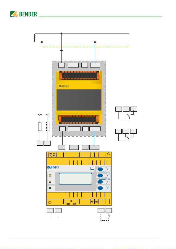
4.9.2 AC: VMD461 with CD440 (earthed system) ......................................... 26
4.9.3 AC: VMD461 with CD440 (unearthed system) .................................... 27
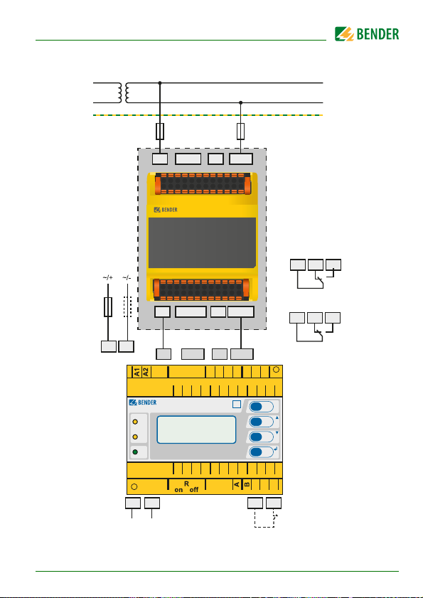
4.9.4 3(N)AC: VMD461 with CD440 (earthed system) ................................ 28
4.9.5 3(N)AC: VMD461 with CD440 (unearthed system) ........................... 29
4.9.6 Example: VMD461 with 2 circuit breakers ............................................ 31
4.9.7 Details regarding the digital inputs (D1, D2, RT1) ............................. 33
4.9.8 Details regarding the internal resistance .............................................. 33
4.10 Commissioning .............................................................................................. 34
4.11 Trigger circuit test by the system erector ............................................. 34
5. Operation and configuration ...................................................................... 35
5.1 Getting to know the user interface ......................................................... 35
5.2 Various displays ............................................................................................. 36
5.2.1 Standard display ............................................................................................ 36
5.2.2 Info display ...................................................................................................... 37
5.2.3 Alarm display .................................................................................................. 37
5.2.4 Menu display ................................................................................................... 37
5.2.5 Toggling between the individual displays ........................................... 38
5.3 INFO button ..................................................................................................... 39
5.4 MENU button .................................................................................................. 39
6. Menu ................................................................................................................ 41
6.1 Menu "1. Alarm/meas. values" .................................................................. 42
6.2 Menu "2. History" ........................................................................................... 43
6.3 Menu "3. Settings" ......................................................................................... 44
6.3.1 General: Password protection .................................................................. 44
6.3.2 Procedure ......................................................................................................... 44
4
VMD461_D00314_01_M_XXEN/10.2018
Page 5

Table of Contents
6.3.3 Menu structure "3. Settings" ...................................................................... 45
6.3.4 Explanatory comments on individual menu items ........................... 52
6.4 Menu "4. System" ........................................................................................... 62
6.4.1 Menu structure "4. System" ....................................................................... 62
6.4.2 Explanatory comments on individual menu items ........................... 64
6.5 Menu "5. Info" ................................................................................................. 65
6.6 Operation via web user interface ............................................................ 65
7. Maintenance, troubleshooting, messages ............................................... 67
7.1 Manual self test .............................................................................................. 67
7.2 Messages and malfunctions ...................................................................... 68
7.3 LEDs .................................................................................................................... 69
8. Technical data VMD461 ............................................................................... 71
8.1 Standards, approvals and certifications ................................................ 77
8.2 Ordering details ............................................................................................. 77
INDEX .................................................................................................................... 81
5
VMD461_D00314_01_M_XXEN/10.2018
Page 6

Page 7
1. Important information
DANGER
WARNING
CAUTION
1.1 How to use this manual
This manual is intended for qualified personnel working in
electrical engineering and electronics!
Always keep this manual within easy reach for future reference.
To make it easier for you to understand and revisit certain sections in this manual, we have used symbols to identify important instructions and information.
The meaning of these symbols is explained below:
This signal word indicates that there is a high risk of danger
that will result in electrocution or serious injury if not
avoided.
This signal word indicates a medium risk of danger that
can lead to death or serious injury if not avoided.
This signal word indicates a low-level risk that can result in
minor or moderate injury or damage to property if not
avoided.
This symbol denotes information intended to assist the user
in making optimum use of the product.
This manual has been compiled with great care. It might nevertheless contain
errors and mistakes. Bender cannot accept any liability for injury to persons or
damage to property resulting from errors or mistakes in this manual.
VMD461_D00314_01_M_XXEN/10.2018
7
Page 8

Important information
1.2 Technical support: service and support
For commissioning and troubleshooting Bender offers you:
1.2.1 First level support
Technical support by phone or e-mail for all
Bender products
Questions concerning specific customer applications
Commissioning
Troubleshooting
Telephone: +49 6401 807-760*
Fax: +49 6401 807-259
In Germany only: 0700BenderHelp (Tel. and Fax)
E-mail: support@bender-service.de
1.2.2 Repair service
Repair, calibration, update and replacement service for Bender products
Repairing, calibrating, testing and analysing Bender products
Hardware and software update for Bender devices
Delivery of replacement devices in the event of faulty or incorrectly
delivered Bender devices
Extended guarantee for Bender devices, which includes an in-house
repair service or replacement devices at no extra cost
Telephone: +49 6401 807-780** (technical issues)
Fax: +49 6401 807-789
E-mail: repair@bender-service.de
Please send the devices for repair to the following address:
+49 6401 807-784**, -785** (sales)
Bender GmbH, Repair-Service,
Londorfer Straße 65,
35305 Grünberg
8
VMD461_D00314_01_M_XXEN/10.2018
Page 9

Important information
1.2.3 Field service
On-site service for all Bender products
Commissioning, configuring, maintenance, troubleshooting for Bender
products
Analysis of the electrical installation in the building (power quality test,
EMC test, thermography)
Training courses for customers
Telephone: +49 6401 807-752**, -762 **(technical issues)
Fax: +49 6401 807-759
E-mail: fieldservice@bender-service.de
Internet: www.bender.de
*Available from 7.00 a.m. to 8.00 p.m. 365 days a year (CET/UTC+1)
**Mo-Thu 7.00 a.m. - 8.00 p.m., Fr 7.00 a.m. - 13.00 p.m.
+49 6401 807-753** (sales)
VMD461_D00314_01_M_XXEN/10.2018
9
Page 10

Important information
1.3 Training courses
Bender is happy to provide training regarding the use of test equipment.
The dates of training courses and workshops can be found on the Internet at
www.bender-de.com -> Know-how -> Seminars.
1.4 Delivery conditions
Bender sale and delivery conditions apply.
For software products the "Softwareklausel zur Überlassung von StandardSoftware als Teil von Lieferungen, Ergänzung und Änderung der Allgemeinen
Lieferbedingungen für Erzeugnisse und Leistungen der Elektroindustrie"
(software clause in respect of the licensing of standard software as part of deliveries, modifications and changes to general delivery conditions for products and services in the electrical industry) set out by the ZVEI (Zentralverband
Elektrotechnik- und Elektronikindustrie e. V.) (German Electrical and Electronic Manufacturer's Association) also applies.
Sale and delivery conditions can be obtained from Bender in printed or electronic format.
1.5 Inspection, transport and storage
Inspect the dispatch and equipment packaging for damage, and compare the
contents of the package with the delivery documents. In the event of damage
in transit, please contact Bender immediately.
The devices must only be stored in areas where they are protected from dust,
damp, and spray and dripping water, and in which the specified storage temperatures can be ensured.
10
VMD461_D00314_01_M_XXEN/10.2018
Page 11

Important information
1.6 Warranty and liability
Warranty and liability claims in the event of injury to persons or damage to
property are excluded if they can be attributed to one or more of the following causes:
Improper use of the device.
Incorrect mounting, commissioning, operation and maintenance of the
device.
Failure to observe the instructions in this operating manual regarding
transport, commissioning, operation and maintenance of the device.
Unauthorised changes to the device made by parties other than the
manufacturer.
Non-observance of technical data.
Repairs carried out incorrectly and the use of replacement parts or
accessories not approved by the manufacturer.
Catastrophes caused by external influences and force majeure.
Mounting and installation with device combinations not recom-
mended by the manufacturer.
This operating manual, especially the safety instructions, must be observed by
all personnel working on the device. Furthermore, the rules and regulations
that apply for accident prevention at the place of use must be observed.
VMD461_D00314_01_M_XXEN/10.2018
11
Page 12

Important information
1.7 Disposal
Abide by the national regulations and laws governing the disposal of this device. Ask your supplier if you are not sure how to dispose of the old equipment.
The directive on waste electrical and electronic equipment (WEEE directive)
and the directive on the restriction of certain hazardous substances in electrical and electronic equipment (RoHS directive) apply in the European Community. In Germany, these policies are implemented through the "Electrical and
Electronic Equipment Act" (ElektroG). According to this, the following applies:
Electrical and electronic equipment are not part of household waste.
Batteries and accumulators are not part of household waste and must
be disposed of in accordance with the regulations.
Old electrical and electronic equipment from users other than private
households which was introduced to the market after 13 August 2005
must be taken back by the manufacturer and disposed of properly.
For more information on the disposal of Bender devices, refer to our website
at www.bender-de.com -> Service & support.
12
VMD461_D00314_01_M_XXEN/10.2018
Page 13

2. Safety instructions
DANGER
2.1 General safety instructions
Part of the device documentation in addition to this manual is the enclosed
"Safety instructions for Bender products".
2.2 Work activities on electrical installations
Only qualified personnel are permitted to carry out the
work necessary to install, commission and run a device or
system.
Risk of electrocution due to electric shock!
Touching live parts of the system carries the risk of:
An electric shock
Damage to the electrical installation
Destruction of the device
Before installing and connecting the device, make sure
that the installation has been de-energised. Observe the
rules for working on electrical installations.
If the device is used outside the Federal Republic of Germany, the applicable
local standards and regulations must be complied with. The European standard EN 50110 can be used as a guide.
VMD461_D00314_01_M_XXEN/10.2018
13
Page 14

Safety instructions
2.3 Intended use
The multifunctional voltage monitoring relay VMD461 monitors frequencies,
undervoltages and overvoltages in DC, AC and 3(N)AC systems. The phase
voltages and/or line-to-line voltages are measured as r.m.s. value and are continuously shown on the device display. The measured value required to trigger the alarm relay is stored. The VMD461 features additional measuring
functions for:
ROCOF df/dt
Vector shift monitoring
Unbalance monitoring
Phase sequence monitoring
The corresponding ANSI codes for all available measuring functions are provided.
Configurable delay times allow considering special installation-specific properties (e.g. device-specific start-up procedures).
The VMD461 requires an external supply voltage.
The optional use of a CD440 coupling device extends the voltage range that
can be monitored to DC/3AC 1200 V or 1AC/3NAC 690 V.
The coupling ensures that on the VMD461 the maximum
permissible input voltage in systems > 230/400 V is not
exceeded.
In order to meet the requirements of applicable standards, the equipment
must be adjusted to local equipment and operating conditions by means of
customised parameter settings. Please heed the limits of the range of application indicated in the technical data. Any other use than that described in this
manual is regarded as improper.
14
VMD461_D00314_01_M_XXEN/10.2018
Page 15

3. Function
3.1 Device features
When combined with a CD440 coupling device, DC systems up to
1200 V, 1AC systems up to 690 V, 3AC systems up to 1200 V and 3NAC
systems up to 690 V can be monitored
All functions are represented in ANSI codes
Monitoring of DC, 1AC, 3(N)AC systems DIN EN 60255-1:2010-9
Single-fault safety
Unbalance, phase failure and phase sequence monitoring
Monitoring of the connected switches and/or disconnectors (config-
urable: NC/NO/off)
Islanding detection df/dt (ROCOF)
Vector shift function
RS-485 interface (data exchange/parameter setting/software update)
Test function to determine the switch-off time
Test button for the trigger circuit
The last 300 network faults can be recalled with time stamp/real-time
clock
Continuous monitoring of the phase voltage and line-to-line voltage
Special switch-on conditions after an infringement of a response value
Language selection (German, English, French)
Backlit graphic LC display
Password protection for device setting
Remote shutdown via ripple control signal receiver
Sealable enclosure
VMD461_D00314_01_M_XXEN/10.2018
15
Page 16

3.2 Glossary
Ter m s De s cr ip ti o n
t
start-up
t
on
t
off
t
(off ) total
Start-up delay
Once the supply voltage is applied, the start-up delay
t
begins. Measured voltage and frequency val-
start-up
ues changing during this time do not influence the
switching state of the alarm relays K1 and K2. At that
moment, the switching state of the alarm relays K1
and K2 depends on the "Start alarm" parameter
(menu: 3.8.4. Start alarm).
Switch-on delay
All switch-on conditions have to be met for the duration of the switch-on delay t
ing alarm relay operates.
Response delay
Minimum period that a limit value infringement must
exist so that the corresponding alarm relay trips.
When the contact monitoring for switches/discon-
nectors is activated, the time until the switch/disconnector actually switches off (t
measured during a test.
The longer one of the two switch-off times is indicated
at t
(off) total
so that the correspond-
on
(off) total
(menu 1.15, see page 42).
Function
) is additionally
16
VMD461_D00314_01_M_XXEN/10.2018
Page 17
Function
CAUTION
3.3 Functional description
Once the supply voltage is applied, the start-up delay t
ured voltage and frequency values changing during this time do not influence
the switching state of the alarm relays K1 and K2.
The devices feature three separately adjustable limit values for overvoltage/
undervoltage as well as overfrequency/underfrequency which are respectively linked to their own response delay t
.
off
Nominal voltage and overvoltage limit values U>, U>>
and U>>> (ANSI code 59)
By means of the nominal voltage and the overvoltage parameters, limit values above the maximum voltages of the
measuring circuit (compare "Chapter 8. Technical data
VMD461) can be set.
The user must ensure that the overvoltage limit values
do not exceed the maximum voltages.
If the measured quantity exceeds or falls below the set response value and the
related response delay t
ue switches and the corresponding LED lights.
has elapsed, the relay assigned to the response val-
off
Fault memory
When the fault memory is disabled, the device automatically attempts to
switch on:
If the measured quantity falls below or exceeds the release value after the
alarm relays have switched, the set switch-on delay t
When the fault memory is enabled, the fault must be manually reset on the
device.
on
start-up
starts.
begins. Meas-
df/dt
A passive method for islanding detection (three-phase voltage and frequency
monitoring).
VMD461_D00314_01_M_XXEN/10.2018
17
Page 18

Function
Vector shift
Vector shift detection is triggered by a sudden phase displacement (vector
shift).
Unbalance
The unbalance is calculated between the phase voltages (in conformity with
IEEE) and the line-to-line voltages (in conformity with NEMA). The higher of
the two values will be compared to the specified response value.
Phase sequence
When phase sequence monitoring is enabled, an alarm is triggered in 3(N)AC
systems as soon as the phase sequence no longer matches the specified value.
In DC systems, an alarm is triggered when the polarity no longer matches the
specified value (measurement time approx. 50 ms).
Automatic self test
The device runs a continuous self test during which internal malfunctions are
detected and shown on the display as error codes. The electrical installation is
not disconnected from the mains during this test.
History memory
The device utilises a history memory for fail-safe storing of up to 300 data
records (date, time, channel, event code, measured value).
After reaching 301 data records, the existing data records, starting with the
oldest one, will be overwritten. After manually activating the deletion process
(menu: 4.1. History), the history memory will be irreversibly deleted.
18
VMD461_D00314_01_M_XXEN/10.2018
Page 19
4. Installation and connection
DANGER
Only qualified personnel are permitted to carry out the
work necessary to install, commission and run a device or
system.
Danger of electrocution due to electric shock!
Touching live parts of the system carries the risk of:
An electric shock
Damage to the electrical installation
Destruction of the device
Before installing and connecting the device, make sure
that the installation has been de-energised. Observe the
rules for working on electrical installations.
4.1 Fuses
Equip the supply voltage of all system ‐components with fuses. IEC 60364-4473 requires protective devices to be used to protect the component in the
event of a short circuit. Bender recommends the use of 6 A fuses.
VMD461_D00314_01_M_XXEN/10.2018
19
Page 20
Installation and connection
DANGER
4.2 Installation instructions
Danger of electric shock!
Make sure that the installation area is disconnected from any
electrical source . Consider the data on the rated voltage
and supply voltage as specified in the technical data!
The maximum length of the connecting cable of device
connections DG1/2, D1, D2, RTG and RT1 is 10 m.
In order to ensure the proper functioning of the VMD461 in
the event of a power failure, an external UPS is to be used.
The devices are suitable for the following types of installation:
Standard distribution panels in accordance with DIN 43871 or DIN rail
mounting in accordance with IEC 60715
Screw mounting using two M4 screws
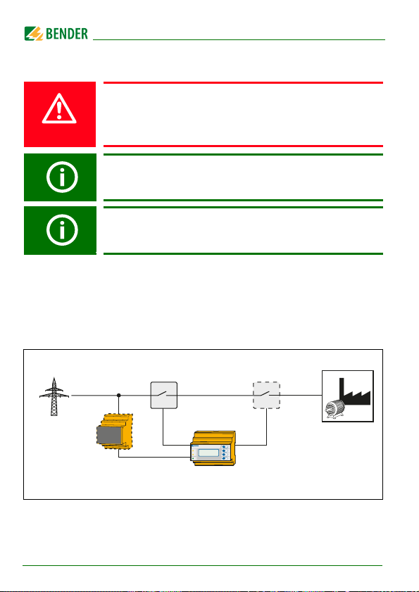
4.3 Schematic diagram
Circuit breaker Circuit breaker
Public grid
20
CD440
(optional)
VMD461
Fig. 4.1: Schematic diagram with circuit breakers
VMD461_D00314_01_M_XXEN/10.2018
Page 21
Installation and connection
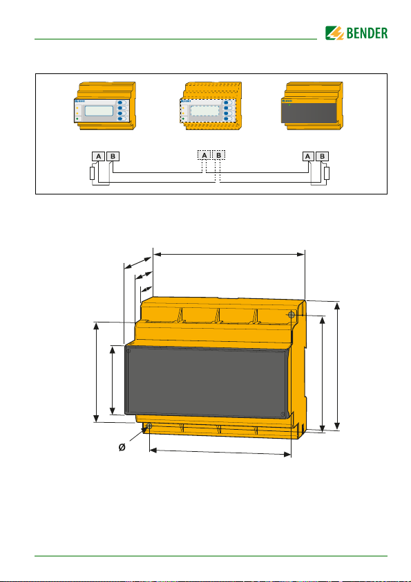
4.4 System structure
(optional)
120 Ω
(DIP switch
VMD461)
4.5 Dimension diagram VMD461
74
47.5
31.1
45
67.5
4.5
Fig. 4.2: Dimension diagram VMD461 (mm)
108
98
COM465IPVMD461 VMD461
120 Ω
(DIP switch
COM465IP)
93
77
VMD461_D00314_01_M_XXEN/10.2018
21
Page 22
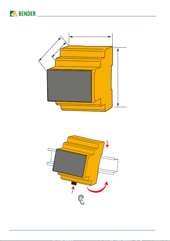
4.6 Dimension diagram CD440
62.5
48.5
Fig. 4.3: Dimension diagram CD440 (mm)
4.7 Mounting on DIN rail
Installation and connection
71.7
93.0
1.
3.
4.
„Klick“
2.
Snap the rear mounting clip of the device into place in such a way that a safe
and tight fit is ensured.
22
VMD461_D00314_01_M_XXEN/10.2018
Page 23
Installation and connection
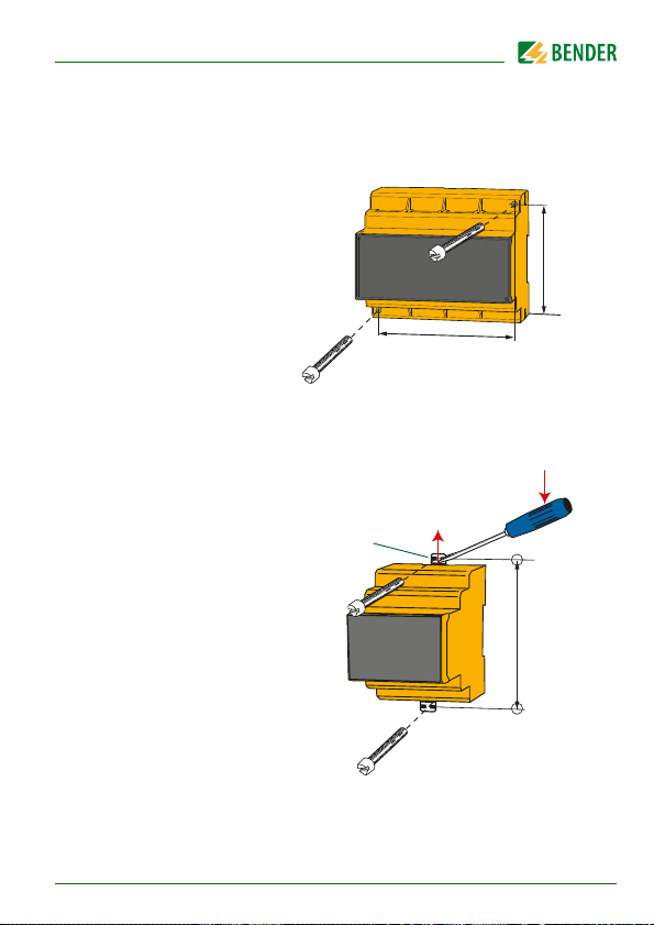
77 mm
98 mm
M4
M4
4.8 Screw mounting
4.8.1 VMD461
4.8.2 CD440
1. Use a tool to position
the rear mounting
clips so that they
project beyond the
enclosure (a second
mounting clip is
required, see ordering information).
2. Then fix the device
using two M4 screws.
B98060008
M4
3.
2.
„Klick“
1.
100 mm
VMD461_D00314_01_M_XXEN/10.2018
M4
4.
23
Page 24
Installation and connection
CAUTION
4.9 Wiring diagram
Depending on the application, connect the device according to the following
wiring diagrams.
The VMD461 can be operated without a CD440 in
appropriate power supply systems (230/400 V).
Risk of unwanted device failure!
Do not supply device from the monitored system. Pay
attention to maximum supply voltage.
24
VMD461_D00314_01_M_XXEN/10.2018
Page 25

Installation and connection
4.9.1 DC: VMD461 with CD440
6 A
L1
L2/DC+
L1 L3 N/DC-L2/DC+
CD440
L3 N/DC-
*
CD440 optional
L+
L-
PE
U
S
L1'
6 A
6 A
A1
A2
LINETRAXX®
ALARM
L2'/DC+' L3'
L1
L2/DC+
VMD461
2
1
ON
A B
Fig. 4.4: DC voltage connection
VMD461_D00314_01_M_XXEN/10.2018
L1' L3' N'/DC-'L2'/DC+'
N'/DC-'
L3
N/DC-
1112142122
D2
D1
DG1/2
V
L1
24
L3
L2/DC+
ESC
INFO
TEST
RESET
MENU
N/DC-
RT1
RTGRT1
RTG
21 241222
K2
11
K1
14
25
Page 26
Installation and connection
4.9.2 AC: VMD461 with CD440 (earthed system)
6 A
L1
L2/DC+
L3 N/DC-
*
N/DC-
D2
V
CD440 optional
24
L3
L1
L2/DC+
ESC
INFO
TEST
RESET
MENU
N/DC-
RTG
RT1
21 241222
11
L1 L3 N/DC-L2/DC+
S
LINETRAXX®
ALARM
ON
L1' L3' N'/DC-'L2'/DC+'
L1' L2'/DC+' L3'
L1
VMD461
2
1
6 A
U
6 A
A1 A2
A B RTGRT1
CD440
L2/DC+
N'/DC-'
L3
1112142122
D1
DG1/2
L1
N
PE
K2
14
K1
26
Fig. 4.5: AC connection (earthed)
VMD461_D00314_01_M_XXEN/10.2018
Page 27
Installation and connection
4.9.3 AC: VMD461 with CD440 (unearthed system)
U
n
L1
L2
PE
6 A
U
S
6 A
A1 A2
LINETRAXX®
2
ALARM
1
ON
6 A
L1
L2/DC+
L1 L3 N/DC-L2/DC+
CD440
L1' L3' N'/DC-'L2'/DC+'
L1' L2'/DC+' L3'
L1
L2/DC+L3N/DC-
VMD461
6 A
L3 N/DC-
N'/DC-'
1112142122
D2
D1
DG1/2
V
A B RTGRT1
Fig. 4.6: AC connection (unearthed system)
*
CD440 optional
24
L3
L1
L2/DC+
ESC
INFO
TEST
RESET
MENU
N/DC-
RTG
RT1
21 241222
11
K1
K2
14
VMD461_D00314_01_M_XXEN/10.2018
27
Page 28

Installation and connection
4.9.4 3(N)AC: VMD461 with CD440 (earthed system)
L1
L2
L3
N
PE
6 A
L2/DC+
L3 N/DC-
L1 L3 N/DC-L2/DC+
CD440
L1' L3' N'/DC-'L2'/DC+'
L1' L2'/DC+' L3'
L1
L2/DC+L3N/DC-
VMD461
N'/DC-'
1112142122
D2
D1
DG1/2
V
*
CD440 optional
24
L3
L2/DC+
L1
ESC
INFO
TEST
RESET
MENU
N/DC-
RTG
RT1
RTGRT1
21 241222
11
K1
K2
14
6 A
U
S
6 A
A1 A2
LINETRAXX®
2
ALARM
1
ON
A B
6 A 6 A
L1
Fig. 4.7: Wiring diagram VMD461 with CD440 (earthed system)
28
VMD461_D00314_01_M_XXEN/10.2018
Page 29

Installation and connection
4.9.5 3(N)AC: VMD461 with CD440 (unearthed system)
L1
L2
L3
N
PE
6 A
L2/DC+
L1 L3 N/DC-L2/DC+
CD440
6 A
L3 N/DC-
*
CD440 optional
6 A 6 A
L1
S
LINETRAXX®
ALARM
L1' L3' N'/DC-'L2'/DC+'
L1' L2'/DC+' L3'
L1
VMD461
2
1
ON
N'/DC-'
L2/DC+L3N/DC-
1112142122
D2
D1
DG1/2
V
L1
24
L3
L2/DC+
ESC
INFO
TEST
RESET
MENU
N/DC-
RT1
RTG
6 A
U
6 A
A1 A2
A B RTGRT1
Fig. 4.8: Wiring diagram VMD461 with CD440 (unear thed system)
VMD461_D00314_01_M_XXEN/10.2018
21 241222
11
K1
K2
14
29
Page 30

Installation and connection
Legend wiring diagrams fig. 4.3…4.8
Element Function
A1, A2
L1, L2/DC+, L3,
N/DC-
Supply voltage U
Power supply connection
11, 12, 14 Connection to alarm relay K1
21, 22, 24 Connection to alarm relay K2
DG1/2,
D1, D2
Contact monitoring
DG1/2: GND
D1: Feedback signal contact to alarm relay K1
D2: Feedback signal contact to alarm relay K2
(feedback signal contacts optionally NC/NO/off)*
RTG, RT1
RTG: GND
RT1: Remote-trip input (optionally NC/NO/off)*
A, B Connection to communication interface BMS bus
R
on/off
Activate or deactivate the terminating resistor of the BMS
bus (120
* Explanation: NC (closed in non-operating state)
NO (open in non-operating state)
off (switched off)
(see ordering details)
s
Ω )
30
VMD461_D00314_01_M_XXEN/10.2018
Page 31

Installation and connection
4.9.6 Example: VMD461 with 2 circuit breakers
Q1 Q2
L1
L2
L3
N
6 A 6 A
6 A
L1
L2/DC+
L3 N/DC-
L1 L3 N/DC-L2/DC+
CD440
*
CD440
optional
L1' L3' N'/DC-'L2'/DC+'
U
S
6 A
6 A
A1 A2
LINETRAXX®
ALARM
ON
2
1
L1' L2'/DC+' L3'
L1
VMD461
N'/DC-'
L2/DC+L3N/DC-
1112142122
D2D1DG1/2
V
L1
24
L2/DC+
INFO
TEST
RESET
MENU
RT1
A B RTGRT1
Fig. 4.9: Wiring diagram VMD461 with 2 circuit breakers
VMD461_D00314_01_M_XXEN/10.2018
L3
ESC
N/DC-
RTG
DG1/2
D1
11 21 2412 2214
K1 K2
D2
31
Page 32

Installation and connection
Legend wiring diagram fig. 4.9
Element Function
A1, A2
L1, L2/DC+, L3,
N/DC-
11, 12, 14 Connection to alarm relay K1
21, 22, 24 Connection to alarm relay K2
Q1, Q2 Circuit breakers
DG1/2,
D1, D2
RTG, RT1
A, B Connection to communication interface BMS bus
R
on/off
* Explanation: *NC (in non-operating state closed)
Supply voltage U
Power supply connection
Contact monitoring circuit breakers Q1/Q2
DG1/2: GND
D1: Feedback signal contact to alarm relay K1
D2: Feedback signal contact to alarm relay K2
(feedback signal contacts optionally NC/NO/off)*
RTG: GND
RT1: Remote-trip input (optionally NC/NO/off)*
Activate or deactivate the terminating resistor of the BMS
bus (120
NO (in non-operating state open)
off (switched off)
(see ordering details)
s
Ω )
Single-fault safety
The device is designed to be single-fault safe. Coupling and relays as well as
their controls for shutdown are designed redundantly.
In order to ensure single-fault safety in the system to be monitored, two circuit
breakers are connected in series (Q1 and Q2, see Fig. 4.9). They have to be
connected to the digital inputs D1 and D2, each with a positively driven, potential-free contact (DG1/2 is the common ground).
The signalling relays K1 and K2 must be connected as shown in Fig. 4.9 and
have to operate in N/C mode.
32
VMD461_D00314_01_M_XXEN/10.2018
Page 33

Installation and connection
4.9.7 Details regarding the digital inputs (D1, D2, RT1)
low : < 4 V DC
high : > 6 V DC
U
= 30 V DC
max
1
24 V
2
DC
Source
Open
Collector
Q1
I < 5 mA
Relay
Contact
Dx
DGx
V1
GND
Dx: D1, D2, RT1
DGx: DG1/2, RTG
Fig. 4.10: Block diagram (simplified representation)
4.9.8 Details regarding the internal resistance
L1 L2/DC+ L3 N/DC-
2
MΩ
L1‘ L2‘/DC+‘ L3‘ N‘/DC-‘
L1 L2/DC+ L3 N/DC-
480
kΩ
MΩ
480
kΩ
2
2,7
MΩ
660
kΩ
MΩ
480
kΩ
2
12 V
R1
μC
CD440
VMD461
Abb. 4.11: Block diagram internal resistance VMD461 and CD440
VMD461_D00314_01_M_XXEN/10.2018
GND
33
Page 34

Installation and connection
4.10 Commissioning
Danger of electric shock!
Improper connection can lead to injury to persons and
damage to the device!
Prior to commissioning make sure that the device is
properly connected!
Initial commissioning
When commissioning the device for the first time you have to:
Select a language (English, German, French) (menu 4.2).
Set date and time (menu 4.3).
You can only change settings in the menus after the settings listed above have
been carried out.
The contrast of the LC display can be adjusted to any
ambient brightness.
Select the contrast ratio from an infinite loop display.
Simultaneously press and hold down the buttons "INFO" and
"MENU" until the display text is clearly readable. After
reaching a black display, the contrast setting process starts
again with a white display.
4.11 Trigger circuit test by the system erector
During commissioning, the system erector has to check the correct function
of the trigger circuit of the switches and/or disconnectors as illustrated in the
wiring diagram of this operating manual, consisting of alarm relay K1, alarm
relay K2, switch/disconnector 1 and switch/disconnector 2.
Press the test button to activate the switches and/or disconnectors.
Tripping must be visualised by the switch and/or disconnector.
Contact monitoring switches and/or disconnectors (optional)
Observe the information about recurrent tests on page 67.
34
VMD461_D00314_01_M_XXEN/10.2018
Page 35

5. Operation and configuration
1
2
3
4
5
6
7
5.1 Getting to know the user interface
LINETRAXX®
Legend
No. Element Function
1
2
ALARM1
ALARM2
3
VMD461_D00314_01_M_XXEN/10.2018
Power On LED, green;
ON
lights when the voltage supply is available and the device
is in operation;
flashes when the device is being started or when an internal device error has occurred
Alarm LEDs, yellow: installation switched off
Only ALARM 1 lights: alarm relay K1 has tripped
and
Only ALARM 2 lights: alarm relay K2 has tripped
ALARM 1 and ALARM 2 light: response value violation of
voltage or frequency, df/dt, vector shift detection, unbalance, phase sequence, remote trip
ALARM 1 and ALARM2 flash: internal device error or
error in contact monitoring
Backlit LC display
VMD461
V
35
Page 36

Operation and configuration
L1-N 229.9V L1-L2 397.2V
L2-N 229.5V L2-L3 401.9V
L3-N 232.9V L3-L1 400.1V
f 50.00 Hz
4
5
6
RESET
7
MENU
Standard display: Toggle between standard display and
INFO
device information
ESC
Menu display: Exit the parameter setting menu
saving; switch to the next higher menu level
Standard display: Use the TEST button (< 1.5 s) to start a
TEST
manual self test which triggers both alarm relays (trigger
test to check the switches/disconnectors). In addition, the
switch-off times are documented, see "Manual self test"
on page 67.
Menu display: arrow-up button for parameter change
and scrolling
Standard display: (> 1.5 s) Acknowledge fault messages
from contact monitoring
Menu display: arrow-down button for parameter
change/scrolling
Standard display: Toggle between standard, menu and
alarm display
Menu display: button
Jump to setting parameter; save the changed parameters
without
5.2 Various displays
5.2.1 Standard display
In the standard display, the line-to-line voltages, the phase voltages and the
frequency are indicated on the display.
36
Fig. 5.1: Standard display
VMD461_D00314_01_M_XXEN/10.2018
Page 37

Operation and configuration
VMD461
22.05.17 12:34
Address: xx
Software: D570Vxx.xx
ALARM 2/3
Undervoltage
U
(1-N) : 180.3 V
Addr.:1 Chan.:1
Exit
1. Alarm/meas.values
2. History
3. Settings
5.2.2 Info display
Device-specific information is indicated on the info display.
Fig. 5.2: Info display
For detailed information, refer to page 39.
5.2.3 Alarm display
Type and source of alarms are indicated on the alarm display in plain text format.
Fig. 5.3: Al arm displ ay
Explanation: In the example above, the second message of three is being indicated (2/3). The current measured value for U
The address "Addr.:" shows the BMS-bus address of the device sending the
(1-N)
is 180.3 V.
alarm. The alarm is output on measuring channel 1 and can be accessed via
channel number 1 in the "Alarm/meas. values" menu.
5.2.4 Menu display
Alarms, currently measured values, device settings as well as the history memory can be called up via the menu display.
VMD461_D00314_01_M_XXEN/10.2018
Fig. 5. 4: Menu displa y
37
Page 38

Operation and configuration
5.2.5 Toggling between the individual displays
You can toggle between the different displays by using the four device buttons. Depending on the type of display (standard display, alarm display, menu
display, info display), the meaning of the buttons is different. The picture below illustrates which button is to be pressed for accessing the individual display. First, you have to distinguish between an alarm condition and no alarm
condition.
no alarm alarm
Info
display
INFO
Standard
display
ESC MENU
Menu
display
ESC
ESC
INFO
ESC
Info
display
Standard
display
ESC
Alarm
display
MENU
Menu
display
MENU
MENUMENU
Fig. 5.5: Toggling between the displays (alarm condition or no alarm condition)
38
VMD461_D00314_01_M_XXEN/10.2018
Page 39

Operation and configuration
5.3 INFO button
Dev ice i nfor matio n in c lear t ext f orma t (Inf o dis play) ca n be c alled up wi th th e
"INFO" button. For this purpose press the "INFO" button in the standard display once. Scroll through the individual lines using the arrow buttons :
Device type
Current date and time
BMS bus address
Software version, measurement technology
Software date, measurement technology
Software version, display
Software date, display
Manufacturer of the device
Address of the manufacturer
Internet address of the manufacturer
Return to standard display via "ESC" or .
5.4 MENU button
Toggling between the standard, alarm and menu display (see page 38).
The individual entries in the menu display can be accessed using the arrow
buttons :
The menu display provides the following submenus:
Exit
1. Alarm/meas.values
2. History
3. Settings
4. System
5. Info
VMD461_D00314_01_M_XXEN/10.2018
39
Page 40

Operation and configuration
40
VMD461_D00314_01_M_XXEN/10.2018
Page 41
6. Menu
1. Alarm/meas. values
2. History
3. Settings
4. System
5. Info
U
, U
, U
, U
, U
, U
(1-N)
(2-N)
(3-N)
Frequency, df/dt (81R), Vect.sh.(78), Status, t
(1-2)
, Unbalance, Phase sequence,
(2-3)
(3-1)
on1
, t
, t
on2
off total
History
1. General
2. Voltage
(59/27)
3. Frequency(81)
4. df/dt (81R)
5. Vect.sh. (78)
6. Unbalance
(47)
7. Phase
sequence(47)
8. Relays
9. Dig. input
Delete history, Language, Clock, Password, Interface, Alarm addresses,TEST,
RESET, Test communication, External devices, Service, Factory settings
Device type, Current date and time, BMS bus address, Software version
measurement technology, Software date measurement technology,
Software version display, Software date display, Manufacturer of the device,
Address of the manufacturer, Internet address of the manufacturer
Coupling, System type, U
U>>> (59.S3), t
U>> (59.S2), t
U> (59.S1), t
U
(on)max
U< (27.S1), t
U<< (27.S2), t
U<<< (27.S3), t
f>>> (81>.S3), t
f>> (81>.S2), t
f> (81>.S1), t
f
(on)max
f< (81<.S1), t
f<< (81<.S2), t
f<<< (81<.S3), t
, f
, U
(on)min
off
off
off
(on)min
off
off
off
off
off
off
off
off
off
Function, Resp.value, Hysteresis, Meas.window, t
Function, Resp.value, t
Function, Resp.value, Hysteresis, t
Function, Phase sequence
Relay mode, t
Device error, TEST, U>>> (59.S3), U>> (59.S2),
U> (59.S1), U< (27.S1), U<< (27.S2, U<<< (27.S3),
f>>> (81>.S3),f>> (81>.S2), f> (81>.S1), f< (81<.S1),
f<< (81<.S2), f<<< (81<.S3), df/dt (81R), Vect.sh. (78),
Unbalance, Phase sequence, Remote trip
Mode, t
, Fault memory, Start alarm,
on
start-up
(L-N)
start-up
, t
, t
start-up
on
, Remote trip
off, ton
off
VMD461_D00314_01_M_XXEN/10.2018
41
Page 42

6.1 Menu "1. Alarm/meas. values"
Select the individual entries by means of the buttons:
Menu
(1-N)
(2-N)
(3-N)
(1-2)
(2-3)
(3-1)
: VALUE
: VALUE
: VALUE
: VALUE
: VALUE
: VALUE
1. U
2. U
3. U
4. U
5. U
6. U
7. Unbalance: VALUE
8. Phase sequence: VALUE
9. Frequency: VALUE
10. df/dt (81R): VALUE
11. Vect.sh.(78): VALUE
12. Status*
13. t
14. t
15. t
*: VALUE
(on1)
*: VALUE
(on2)
(off) total
*: VALUE
For each of these entries you can check whether an alarm exists or not:
= no alarm
= alarm
The numbering of the measuring channels matches the BMS
bus channels.
*
Status: measuring channel 12: The text depends on the existing mes-
sages.
t
: measuring channel 13/14: Current switch-on delay of alarm relay
(ON…)
K1 and alarm relay K2.
t
: measuring channel 15
(off) total
(only when contact monitoring is connected): Indicates the total time
of the shutdown process of the alarm relays with the switches/disconnectors.
42
VMD461_D00314_01_M_XXEN/10.2018
Page 43

Menu
History no. 297
From: 01.05.17 / 15:57:00
Ack.:
To: 01.05.17 / 16:07:03
History No. 297
Undervoltage
Min. 21 V/max.198 V
Addr.:2 Chan.:1
6.2 Menu "2. History"
The fail-safe history memory stores up to 300 events (alarms, tests) with information about alarms and acknowledgements and the time the event happened. If the history memory is full, the oldest entry will be deleted in the
event of an alarm to create space for the new entry (FIFO principle).
For details about deleting the entire history memory manually, refer to
page 64.
Fig. 6. 1: Histor y (overview)
Legend for Fig. 6.1:
Line 1: Event number
Line 2: Start of the event: Date/time
Line 3: Acknowledgement of the event: Date/time
Line 4: End of the event: Date/time
Navigating through the list:
1. If you are searching for an event that occurred at a specific time, scroll
through the different entries using the arrow buttons.
2. Calling up details: Use the button to call up the current history
memory entry.
VMD461_D00314_01_M_XXEN/10.2018
Fig. 6.2: History (detail)
43
Page 44

Menu
Please enter
password:
0 0 0
Legend for Fig. 6.2:
Line 1: Data record number
Line 2: Alarm status and alarm text (e.g. undervoltage,
underfrequency,…)
= no alarm
= alarm, fault
Line 3: Minimum and maximum measured value after the occur-
rence of an alarm
Line 4: BMS-bus address and measuring channel of the device
sending the signal
6.3 Menu "3. Settings"
6.3.1 General: Password protection
Settings can be password protected (menu 4.4). If the password is enabled, all
settings can be displayed. When an attempt is made to change settings, the
password entry screen appears automatically:
Once a valid password has been entered, access will be granted to settings in
all menus until menu mode is exited. If you cannot remember your password,
contact the Bender Service.
6.3.2 Procedure
The values can be changed in the third level of the menu (column "twice ")
using .
There are two different ways to exit the settings menu:
Save and exit: " "
Exit without saving: "ESC"
44
VMD461_D00314_01_M_XXEN/10.2018
Page 45

Menu
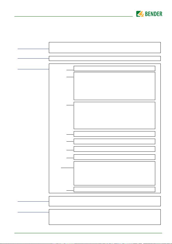
6.3.3 Menu structure "3. Settings"
The following table gives an overview of the menu structure.
Menu:
Settings
once twice
3.1 General Exit
1. Coupling yes
2. System type 3NAC
3. U(L-N) 50…260 V 230 V
4. t
5. Remote trip off
3.2 Voltage
(59/27)
Exit
1. U>>>
2. t
3. U>>
4. t
5. U>
6. t
7. U
no
DC
1AC
3AC
(start-up)
200 ms…60 min
N/C
N/O
(59.S3)
* 50 ms…60 min --
(off )
(59.S2)
* 50 ms…60 min --
(off )
(59.S1)
* 50 ms…60 min 100 ms
(off )
(on)max
off
100…150 %
off
100…150 %
off
100…150 %
off
100…150 %
Factory setting
no
3NAC
200 ms
off
off
off
110 %
105 %
VMD461_D00314_01_M_XXEN/10.2018
45
Page 46

Menu
Menu:
Settings
3.2 Voltage (59/
27)
3.3 Frequency
(81)
once twice
8. U
(on)min
off
1…100 %
9. U<
(27.S1)
10. t
* 50 ms…60 min 100 ms
(off )
11. U<<
(27.S2)
* 50 ms…60 min --
12. t
(off )
13. U<<<
14. t
(27.S3)
* 50 ms…60 min --
(off )
off
1…100 %
off
1…100 %
off
1…100 %
Exit
1. f>>>
(81>.S3)
2. t
* 50 ms…60 min --
(off)
3. f>>
(81>.S2)
* 50 ms…60 min --
4. t
(off)
5. f>
(81>.S1)
6. t
* 50 ms…60 min 100 ms
(off)
7. f
(on)max
8. f
(on)min
off
50…65 Hz
off
50…65 Hz
off
50…65 Hz
off
50…65 Hz
off
45…60 Hz
Factory setting
95 %
90 %
off
off
off
off
51.50 Hz
50.10 Hz
49.90 Hz
46
VMD461_D00314_01_M_XXEN/10.2018
Page 47

Menu
Menu:
Settings
3.3 Frequency
once twice
9. f<
(81)
10. t
11. f<<
12. t
13. f<<<
14. t
3.4 df/dt (81R) Exit
1. Function off
2. Resp. value 0.05…9.95 Hz/s 1.00 Hz/s
3. Hysteresis 1…50 % 20.0 %
4. Meas. window 50 ms…1 s 200 ms
5. t
6. t
3.5 Vect.sh. (78) Exit
1. Function off
2. Resp. value 1…25 ° 8.0 °
(81<.S1)
off
45…60 Hz
* 50 ms…60 min 100 ms
(off)
(81<.S2)
* 50 ms…60 min --
(off)
(81<.S3)
off
45…60 Hz
off
45…60 Hz
* 50 ms…60 min --
(off)
on
* 50 ms…60 min 100 ms
(off )
*off
(on)
50 ms…60 min
all
L3
L2
L1
Factory setting
48.50 Hz
off
off
off
off
off
VMD461_D00314_01_M_XXEN/10.2018
47
Page 48

Menu
Menu:
Settings
once twice
3.5 Vect.sh. (78) 3. t
4. t
3.6 Unbalance
(47)
Exit
1. Function off
2. Resp. value 1…50 % 5.0 %
3. Hysteresis 1…50 % 20.0 %
4. t
3.7 Phase
sequence (47)
Exit
1. Function on
2. Phase sequence right
(start-up)
off
50 ms…60 min
(on)
off
50 ms…60 min
on
* 50 ms…60 min 100 ms
(off)
off
left
Factory setting
2.00 s
off
off
on
right
48
VMD461_D00314_01_M_XXEN/10.2018
Page 49

Menu
Menu:
Settings
once twice
3.8 Relay ** Exit
1. Relay mode N/C
2. t
3. Fault memory on
4. Start alarm on
5. Device error on
6. TEST on
7. U>>>
8. U>>
9. U>
10. U<
(on)
(59.S3)
(59.S2)
(59.S1)
(27.S1)
Factory setting
N/C
N/O
50 ms…60 min 10 s
on
off
Duration
off
off
on
off
on
off
on
on
off
on
on
off
on
on
off
on
on
off
VMD461_D00314_01_M_XXEN/10.2018
49
Page 50

Menu
Menu:
Settings
once twice
3.8 Relay ** 11. U<<
12. U<<<
13. f>>>
14. f>>
15. f>
16. f<
17. f<<
18. f<<<
19. df/dt
20. Vect.sh.
21. Unbalance on
22. Phase
sequence
23. Remote trip on
(27.S2
(27.S3)
(81>.S3)
(81>.S2)
(81>.S1)
(81<.S1)
(81<.S2)
(81<.S3)
(81R)
(78)
on
off
on
off
on
off
on
off
on
off
on
off
on
off
on
off
on
off
on
off
off
on
off
off
Factory setting
on
on
on
on
on
on
on
on
on
on
on
on
on
50
VMD461_D00314_01_M_XXEN/10.2018
Page 51

Menu
Menu:
Settings
once twice
Factory setting
3.9 Dig. input ** Exit
1. Mode off
off
N/C
N/O
2. t
(start-up)
off
50 ms…60 min
--
Tab. 6.1: Settings menu
Note:
* t
can only be set when the corresponding parameter U…
(off)
or f… is activated.
** The relay or digital input number is displayed in the first line.
Change selection: Jump to the first line using and change
entry.
VMD461_D00314_01_M_XXEN/10.2018
51
Page 52

Menu
6.3.4 Explanatory comments on individual menu items
General (menu 3.1)
Activation of external coupling device CD440 (menu 3.1.1)
Is the VMD461 operated with a CD440 coupling device?
yes VMD461 with CD440
no VMD461 without CD440
System type (menu 3.1.2)
3NAC The system to be monitored consists of three phases
DC The system to be monitored consists of the two conductors
1AC The system to be monitored consists of one phase
including the neutral conductor. In the "1. Alarm/meas.
values" menu all measured values are available. The
nominal voltage is indicated as phase voltage (U
(L-N)
).
DC+ and DC–.
When set to system type "DC", the system to be monitored
must be connected to the terminals L2/DC+ and N/DC– !
In the "1. Alarm/meas. values" menu, the non-applicable
display indications for phase voltages and line-to-line
voltages, unbalance, phase sequence, frequency and
vector shift can be blanked (indication: --).
including the neutral conductor. In the "Alarm/meas.
values" menu, the non-applicable display indications for
line-to-line voltages, unbalance, and phase sequence can
be blanked (indication: --).
The nominal voltage is indicated as phase voltage (U
(L-N)
).
52
When set to system type "1AC", the system to be monitored
must be connected to the terminals L1 and N!
VMD461_D00314_01_M_XXEN/10.2018
Page 53

Menu
3AC The system to be monitored consists of three phases
without neutral conductor. In the "1. Alarm/meas. value"
menu, non-applicable display indications for phase
voltages can be blanked (indication: --).
The nominal voltage is indicated as line-to-line voltage
(U
).
Remote trip (menu 3.1.5)
(L-L)
This connection can optionally be activated and is intended
for disconnecting the electrical installation from the mains
supply by remote control via an external contact. After
activating the remote control, the switches/disconnectors
are switched after ≤ 50 ms.
Voltage (59/27) (menu 3.2)
The VMD461 can consider three different over- and undervoltage limit values.
A separate response delay t
The limit values for U
(on)max
For the intended use, the following requirement must be
complied with when setting several over- and undervolt-
age limit values:
[U>>>] > [U>>] > [U>] > [U
[U<<] > [U<<<].
can be set for each limit value.
(off)
and U
are also set here.
(on)min
(on)max
] > [U
(on)min
] > [U<] >
Separate switch-on limit values can be defined by means of the U
eters.
(on)…
param-
If the parameters are set to "off", the corresponding switch-off limit values are
also the switch-on limit values (no hysteresis). The measured values may not
exceed these limit values to allow connection of the electrical installation.
VMD461_D00314_01_M_XXEN/10.2018
53
Page 54

Menu
Frequency (81) (menu 3.3)
The VMD461 can consider three different over- and underfrequency limit values. A separate response delay t
The limit values for f
(on)max
For the intended use, the following requirement must be
complied with when setting several over- and undervolt-
age limit values:
[f>>>] > [f>>] > [f>] > [f
[f<<<].
can be set for each limit value.
(off)
and f
are also set here.
(on)min
(on)max
] > [f
] > [f<] > [f<<] >
(on)min
Separate switch-on limit values can be defined by means of the f
(on)…
parameters.
If the parameters are set to "off", the corresponding switch-off limit values are
also the switch-on limit values (no hysteresis). The measuring values may not
exceed these limit values to allow connection of the electrical installation.
df/dt (81R) (menu 3.4)
Islanding detection (df/dt) (ROCOF)
The VMD461 uses a passive method for islanding detection (three-phase voltage and frequency monitoring).
The monitoring of the "Rate of Change of Frequency" (df/dt)
is an islanding detection function.
If a subnetwork is shut down by the energy provider it might still be supplied
by electrical installations contained in the subnetwork. Underfrequency and
overfrequency monitoring might not be sufficient to detect this dangerous,
uncontrollable state, since the generators try to keep the frequency at the
nominal frequency level.
Due to an unbalance between the generated energy and the consumed energy the frequency fluctuates around the nominal frequency. If this happens at
a certain minimum speed, it is a sign of islanding and the VMD461 shuts down
the electrical installation.
54
VMD461_D00314_01_M_XXEN/10.2018
Page 55

Menu
Function (menu 3.4.1) Enable/disable df/dt monitoring.
Resp. value (menu 3.4.2) Specify a limit value at which tripping is to be
executed (in 0.05 Hz/s steps).
Hysteresis (menu 3.4.3) Adjust hysteresis.
Meas. window (menu 3.4.4) Period of time used to calculate the average of
the frequency changes (positive and negative
changes cancel each other out). The bigger the
measuring window selected the less sensitive
will the df/dt function be.
t
(menu 3.4.5) Response delay: Period of time during which the
(off)
limit value
df/dt must be violated until the VMD461 shuts
down the electrical installation.
t
(menu 3.4.6) Switch-on delay, when df/dt has caused a
(on)
shutdown. You can choose between a precise
value and "off". When the "off" setting is
selected, the normal switch-on delay t
menu 3.8.3 will be used.
(on)
from
VMD461_D00314_01_M_XXEN/10.2018
55
Page 56

Menu
Vector shift detection (78) (menu 3.5)
Vector shift detection is triggered by a sudden phase displacement (vector
shift).
A phase displacement may occur when a mechanical generator is used for
public grid infeed and the load is changing suddenly (as can be the case with
islanding).
In addition to the risk of islanding synchronisation to the rest of the system
can be lost during the interruption so that the generator and parts of the drive
may become electrically and mechanically overloaded during reconnection.
Function (menu 3.5.1) Enable/Disable vector shift detection and indicate
Resp. value (Menu 3.5.2) Specify a limit value at which tripping is to be
t
(menu 3.5.3) Time during which vector shift detection is
(start-up)
t
(menu 3.5.4 ) Switch-on delay after the vector shift detection has
(on)
which phases should be monitored (L1 / L2 / L3 / all
/ off). If all phases are selected, the vector shift must
occur on all three phases simultaneously.
Otherwise the device will not trip.
If the device is set to single-phase connection
(3.1.2 System type: 1 AC) and vector shift detection
is ena ble d, L 1 wi ll alw ays be a uto mat ic all y se lec ted
as the phase to be monitored (independent of the
current parameter setting).
executed (in ° )
suppressed. This time begins as soon as the
VMD461 has connected the electrical installation.
t
has to ensure that there is no tripping due
(start-up)
to voltage fluctuations during the switch-on
period.
resulted in a shutdown. You can choose between
a precise value and "off". In case of "off", the normal
switch-on delay from menu 3.8.3 is used.
56
VMD461_D00314_01_M_XXEN/10.2018
Page 57

Menu
Unbalance (47) (menu 3.6)
The unbalance is calculated between the phase voltages and the line-to-line
voltages. The higher of the two values will be compared to the specified response value and can lead to a shutdown of the electrical installation.
Function (menu 3.6.1) Enable/Disable monitoring
Resp. value (menu 3.6.2) Specify a limit value at which tripping is to be
Hysteresis (menu 3.6.3) Set a hysteresis
t
(menu 3.6.4) Response delay: Period of time during which the
(off)
executed (in 0.1 % steps)
unbalance limit value must be violated until the
VMD461 shuts down the electrical installation
Phase sequence (47) (menu 3.7)
AC system:
When phase sequence monitoring is enabled, the alarm relays K1 and/or K2
trip when the detected phase sequence no longer matches the specified value (measurement time approx. 50 ms).
Function (menu 3.7.1) Enable/Disable monitoring phase sequence
Phase sequence(menu 3.7.2)Select specified phase sequence (right, left)
DC system:
When phase sequence monitoring is enabled, the polarity of the system is
tested.
The alarm relays K1 and/or K2 trip when the polarity no longer matches the
specified value (measurement time approx. 50 ms).
Function (menu 3.7.1) Enable/Disable monitoring polarity
Phase sequence (menu 3.7.2)Select polarity
right: L2/DC+= +
N/DC–= –
left: L2/DC+= –
VMD461_D00314_01_M_XXEN/10.2018
N/DC–= +
57
Page 58

Relays (menu 3.8)
Alarm assignments to the alarm relays
Set here which messages should make the alarm relays switch.
The alarm relay to be adjusted is indicated in the first line.
Entering changes:
Use the button to jump to the top line, activate
modification with the button and modify alarm relay.
The following alarms can be assigned to the alarm relays K1 and K2:
Start alarm
Device error
TEST
U>, U>>, U>>> (59.S1…3)
U<, U<<, U<<< (27.S1…3)
f>, f>>, f>>> (81>.S1…3)
f<, f<<, f<<< (81<.S1…3)
df/dt (81R)
Vector shift (78)
Unbalance
Phase sequence
Remote trip
Relay mode (menu 3.8.1)
N/C Normally closed -
Relay is energised during normal operation and will be
deactivated in the event of a fault.
N/O Normally open -
The relay is de-energised in normal operation and will be
activated in the event of a fault.
Menu
58
VMD461_D00314_01_M_XXEN/10.2018
Page 59

Menu
Switch-on delay t
t
can be adjusted separately for each alarm relay.
on
(menu 3.8.2)
on
The alarm relay to be adjusted is indicated in the first line.
Entering changes:
Use the button to jump to the top line, activate
modification with the button and modify settings.
All switch-on conditions of the measuring functions assigned to the alarm relay have to be met for the duration of the switch-on delay t
so that the cor-
on
responding alarm relay operates.
When all switch-on conditions are met, the corresponding switch-on delay t
elapses.
on
It is possible to view the time that is still required for switchon:
menu 1.13 (t
menu 1.14 (t
on1
on2
) or
)
Special case:
If the electrical installation has been shut down due to a vector shift or an islanding detection, a different switch-on delay can be defined for these cases.
Menu: 3.4. df/dt
Menu: 3.5. Vect.sh.
VMD461_D00314_01_M_XXEN/10.2018
59
Page 60

Menu
Fault memory(menu 3.8.3)
The fault memory behaviour can be adjusted separately for each alarm relay.
The element to be adjusted is indicated in the first line.
Entering changes:
Use the button to jump to the top line, activate
modification with the button and modify settings.
The fault memory can be enabled, disabled or set to continuous mode. If the
fault memory is set to "cont." mode, a stored alarm remains in the memory
even if there is a failure of the supply voltage.
Setting options:
on The alarm relays remain in the alarm state until the supply
voltage is interrupted or a reset is carried out.
off The alarm relays return to their initial position as soon as the
limit value is no longer violated.
cont. The alarm relays remain in the alarm state even after the
supply voltage has failed until a reset is carried out.
Start alarm (menu 3.8.4)
on Starting the device with a simulated alarm
off Starting the device without a simulated alarm
When the start alarm is activated, K1 or K2 switches to alarm state after applying the supply voltage. The device remains in alarm state for the delay time
t
. Afterwards, the switch-on delays t
(start-up)
stallation condition. Then, the alarm relays K1 or K2 switch back, provided that
) elapse according to the in-
(on…
no fault has been detected at the measuring input.
Device error (menu 3.8.5)
The alarm assignment "Device errors" includes internal errors as well as external errors in the contact monitoring.
60
VMD461_D00314_01_M_XXEN/10.2018
Page 61

Menu
Dig. input (contact monitoring) (menu 3.9)
Contact monitoring can be enabled separately for the switched-on and
switched-off condition of the installation. The following table shows an overview of the settings:
Mode
(menu 3.9.1)
Contact monitoring when installation is
switched on switched off
off ——
N/C or N/O X
(delay 500 ms,
not configurable)
t
(menu 3.9.2)
(start-up)
off 50 ms…60 min
— X
Dig. input Select digital input that is to be configured.
The digital input to be configured is indicated in the first line.
Entering changes:
Use the button to jump to the top line, activate
modification with the button and modify settings.
Mode (menu 3.9.1) Select operating mode of the digital input.
off Disable contact monitoring
N/C Normally closed
In non-operating state, the auxiliary contact is
closed.
N/O Normally open
In non-operating state, the auxiliary contact is open.
t
(menu 3.9.2) Configure time delay after which the VMD461 (after
(start-up)
switching on the electrical installation) should
check the switching contact monitoring of the
switches/disconnectors connected to alarm relays
K1and/or K2.
VMD461_D00314_01_M_XXEN/10.2018
61
Page 62

Menu
off Disable contact monitoring of connected instal-
lation
50 ms…60 min Time delay contact monitoring
.
A delay of 500 ms is recommended for active contact
monitoring of the connected installation. In case of slow
motor-operated switches/disconnectors it may be necessary
to increase t
(start-up)
.
6.4 Menu "4. System"
The following table gives an overview of the menu structure. The values can
be changed in the third level of the menu (column "twice ") using .
There are two different ways to exit the system menu:
Save and exit: " "
Exit without saving: "ESC"
6.4.1 Menu structure "4. System"
Menu: System
1. History Exit
2. Language Exit
once twice
Delete
1)
Delete
Cancel
English
German
Frenc h
62
VMD461_D00314_01_M_XXEN/10.2018
Page 63

Menu
Menu: System
3. Clock Exit
4. Password Exit
5. Interface Exit
6. Alarm addresses Exit
7. TEST Cancel
8. RESET Cancel
9. Test communication
once twice
Format d. m.y
Date Toggling between date elements
Time Toggling between hour and
Summertime auto
Password * * *
Status off
Address
Address xxx
TEST
RESET
Exit
1. Channel
m-d-y
with
minute with
off
Toggling between positions with
on
1…90
1: Master
2…90: Slave
1…150: off/on
Test is carried out
Reset is carried out
Channel (1…12)
VMD461_D00314_01_M_XXEN/10.2018
63
Page 64

Menu
Menu: System
10. External devices Exit
11. Service Service menu only available for Bender service
12. Factory settings Cancel fac-
once twice
1…150: Address of VMD461 and
List of connected
devices
tory settings
Tab. 6.2: Menu structure "4. System"
external devices
Restore factory settings
6.4.2 Explanatory comments on individual menu items
Clear history memory (menu 4.1)
After starting the deletion process the history memory is
irreversibly deleted.
Password
Manual self test (menu 4.7 )
Factory settings (menu 4.12 )
(menu 4.4 )
Password protection is deactivated (off) by default.
Navigate through the system also when the password
protection is activated. However, the password is required for
change of parameters.
The self test can only be started manually when the
VMD461 is connected and free of alarms. The alarm relays
K1 and K2 switch when the corresponding alarm
assignment (menu: 3.8.6 "Test") is activated.
Activating the factory settings will reset the device to the
default upon delivery.
64
VMD461_D00314_01_M_XXEN/10.2018
Page 65

Menu
6.5 Menu "5. Info"
The following table gives an overview of the information to be called up.
Scroll through the individual lines using the arrow buttons :
Device type
Current date and time
BMS bus address
Software version, measurement technology
Software date, measurement technology
Software version, display
Software date, display
Manufacturer of the device
Address of the manufacturer
Internet address of the manufacturer
6.6 Operation via web user interface
The parameters of the VMD461 can be set via the network when using a protocol converter (CP700, COM465, …).
Consider logical dependencies when setting
parameters:
Since, for example, the setting limits of the parameter
"Nominal voltage" depend on "Coupling" and "System type",
these must be configured and saved before. Only after doing
this, the nominal voltage can be adjusted.
VMD461_D00314_01_M_XXEN/10.2018
65
Page 66

Menu
66
VMD461_D00314_01_M_XXEN/10.2018
Page 67

7. Maintenance, troubleshooting, messages
7.1 Manual self test
The self test can only be started manually when the electrical installation has
been started by the VMD461 and is free of alarms (both alarm LEDs are off).
In case of a manual self test, alarm relays K1 and K2 trip if the
corresponding alarm assignment is activated in menu 3.8.6.
"Test".
Start of the manual self test:
1. Press the test button in the standard display (> 1.5 s) or
2. Select in the menu 4.7 Test.
The alarm relays K1 and K2 switch during the self test and open or close the
contacts 11/12/14 and 21/22/24.
When contact monitoring is activated for switch/disconnector K1 and/or
K2, the time until the switch/disconnector has actually switched off is additionally measured (t
The longer one of the two switch-off times is shown as an alarm in the display
for 10 seconds and can be read in the menu 1.15 (t
shut down.
The manual self test is stored in the history memory.
(off) total
).
) until the device is
(off) total
VMD461_D00314_01_M_XXEN/10.2018
67
Page 68

Maintenance, troubleshooting, messages
7.2 Messages and malfunctions
In case of messages and malfunctions, alarm relays K1 and
K2 trip if the corresponding alarm assignment is activated in
menu 3.8.6. "Device error".
Both alarm LEDs flash: internal device error or fault in contact monitoring
The (error) code or the message is shown in clear text on the display.
Code/
message
1…20, 23Both alarm
Contact
monitor.
K1
Contact
monitor.
K2
Remote
trip
LED Meaning Remedy
LEDs flash
Both alarm
LEDs flash
Both alarm
LEDs light
continuously
68
Internal error Write down the error code
"xx2 and contact Bender
service.
Error: Contact
monitoring K1
(D1)
Error: Contact
monitoring K2
(D2)
Remote shutdown active
After rectifying the fault at
the switch/disconnector/
main switch (e.g. manual
connection of the backup
switch), the fault is automatically cleared. If the same fault
occurs three times within 30
seconds at the digital input,
normal operation must be
started again after fault elimination by pressing the
"RESET" button (in the standard display).
Connect RTG/RT1 or deactivate input in the menu (off)
VMD461_D00314_01_M_XXEN/10.2018
Page 69

Maintenance, troubleshooting, messages
7.3 LEDs
The state of the VMD461 can be determined by means of the LEDs. The following table provides an overview of the possibilities.
LEDs Meaning Action
2
ALARM
1
ON
2
ALARM
1
ON
yellow off
yellow off
green lights
yellow lights
yellow lights
green lights
Normal operation
mode: device in
operation, all the
measured values
are within the
specified limits
Alarm, limit value
of K1 and K2 violated
2
ALARM
1
ON
2
ALARM
1
ON
2
ALARM
1
ON
VMD461_D00314_01_M_XXEN/10.2018
yellow lights
yellow off
green lights
yellow off
yellow lights
green lights
yellow
flashes
yellow
flashes
green lights
Alarm, limit value
of K2 violated
Alarm, limit value
of K1 violated
Error contact monitoring or internal
error
Check switches/
disconnectors * ;
in case of int.
errors:
contact
service
69
Page 70

Maintenance, troubleshooting, messages
LEDs Meaning Action
2
ALARM
1
ON
yellow off
yellow off
green flashes
Device starts
(> 10 s): internal
device error
Wait (< 10 s)
Contact
service
*
After eliminating the error at the switch/disconnector, the fault is automatically cleared.
If the same fault occurs three times within 30 seconds at the
digital input, normal operation must be started again after
fault elimination by pressing the "RESET" button (in the
standard display).
70
VMD461_D00314_01_M_XXEN/10.2018
Page 71

8. Technical data VMD461
Insulation coordination of the device combination VMD461/CD440:
Rated voltage ≤ 1000 V ............................................................................................acc. to IEC 60664-1/IEC 60664-3
Rated voltage > 1000 V .............................................................................................................acc. to EN 50178:1998
Definitions
Measuring circuit (IC1) ...............................................................................................CD440 (L1, L2/DC+, L3, N/DC–)
Measuring circuit (IC2) ...........................................................................................VMD461 (L1, L2/DC+, L3, N/DC–)
Supply circuit (IC3) ............................................................................................................................. VMD461 (A1, A2)
Control circuit (IC4)................................................................................................VMD461 (D1, D2, DG1/2, RTG, RT1)
Output circuit 1 (IC5).....................................................................................................................VMD461 (11, 12, 14)
Output circuit 2 (IC6).....................................................................................................................VMD461 (21, 22, 24)
Output circuit 3 (IC7)...............................................................................................................................VMD461 (A, B)
Rated voltage
IC1...........................................................................................................................................................DC, 3AC: 1200 V
..............................................................................................................................................................1AC, 3NAC: 690 V
IC2............................................................................................................................................................................400 V
IC3............................................................................................................................................................................250 V
IC5, IC6 .................................................................................................................................................................... 250 V
Rated impulse voltage
Overvoltage category.................................................................................................................................................... III
Max. altitude........................................................................................................................................................2000 m
IC1/(IC2…6)....................................................................................................................................................... 10.5 kV
IC2/(IC3…6).............................................................................................................................................................4 kV
IC3/(IC4…6).............................................................................................................................................................4 kV
IC4/(IC5…6).............................................................................................................................................................4 kV
IC5/IC6........................................................................................................................................................................4 kV
Rated insulation voltage
Pollution degree..............................................................................................................................................................3
IC1/(IC2…6).........................................................................................................................................DC, 3AC: 1250 V
............................................................................................................................................................. 1AC, 3NAC: 800 V
VMD461_D00314_01_M_XXEN/10.2018
71
Page 72

Technical data VMD461
IC2/(IC3…6)..........................................................................................................................................................400 V
IC3/(IC4…6)..........................................................................................................................................................400 V
IC4/(IC5…6)..........................................................................................................................................................400 V
IC5/IC6....................................................................................................................................................................... 4 kV
Protective separation (reinforced insulation):
IC1/(IC3…6)................................................................................................DC, 3AC: Overvoltage category III, 1250 V
.................................................................................................................. 1AC, 3NAC: Overvoltage category III, 1000 V
IC2/(IC3…6)..........................................................................................................................................................300 V
IC3/(IC4…6)..........................................................................................................................................................300 V
IC4/(IC5…6)..........................................................................................................................................................300 V
IC5/IC6.....................................................................................................................................................................300 V
Voltage test (routine test ) acc. to IEC 60255-27/DIN EN 50178:1998
IC2/(IC3…6).......................................................................................................................................................2.21 kV
IC3/(IC4…6).......................................................................................................................................................2.21 kV
IC4/(IC5…6).......................................................................................................................................................2.21 kV
IC5/IC6.................................................................................................................................................................. 2.21 kV
Supply voltage
Nominal supply voltag e U
Tolerance U
s
Nominal frequency range U
Power consumption at AC 230 V..................................................................................................... < 3.5 W/ < 7.5 VA
....................................................................................................................... 100…240 V
s
......................................................................................................................................................... ±25 %
..................................................................................................................... DC, 50/60 Hz
s
maximum ................................................................................................................................. 3.5 W / 9 VA
Measuring circuit
VMD461
System type .....................................................................................................................................DC, 1AC, 3AC, 3NAC
Nominal voltage U
n
(L-N) ..................................................................................................................................... AC 50…260 V
(L-L)...................................................................................................................................... AC 87…450 V
(DC+ / DC–)........................................................................................................................ DC 50…450 V
Measuring range........................................................................................................................................0…1.15 x U
Overload capacity............................................................................................................................... 1.5 x U
Response values.............................................................................................................................................1…150 %
Operating uncertainty U
...................................................................................................................................≤ ±1 %
n
n max
for 5 s
n
72
VMD461_D00314_01_M_XXEN/10.2018
Page 73

Technical data VMD461
Resolution of setting Un............................................................................................................................................. 1 %
Rated frequency ......................................................................................................................................... DC, 50/60 Hz
Frequency range U
Resolution of setting f.......................................................................................................................................... 0.05 Hz
................................................................................................................................DC, 45…65 Hz
n
Relative uncertainty f .....................................................................................................................................≤ ±0.1 %
VMD461 with CD440
System type .....................................................................................................................................DC, 1AC, 3AC, 3NAC
Nominal voltage U
n
(L-N)..........................................................................................................................................AC 250…690 V
(L-L)........................................................................................................................................ AC 440…1200 V
(DC+ / DC–)...........................................................................................................................DC 250…1200 V
Nominal voltage U
for Canada
n
(L-N)..........................................................................................................................................AC 250…600 V
(L-L)...........................................................................................................................................AC 440…600 V
(DC+ / DC–).............................................................................................................................DC 250…600 V
Measuring range........................................................................................................................................0…1.15 x U
Overload capacity............................................................................................................................... 1.5 x U
Response values.............................................................................................................................................1…150 %
Operating uncertainty U
Resolution of setting U
Rated frequency ......................................................................................................................................... DC, 50/60 Hz
Frequency range U
..................................................................................................................................≤ ±2 %
n
............................................................................................................................................. 1 %
n
................................................................................................................................DC, 45…65 Hz
n
n max
for 5 s
Resolution of setting f..........................................................................................................................................0.05 Hz
Relative uncertainty f .....................................................................................................................................≤ ±0.1 %
Recording of measurement values, switch-on condition
U<, U<<, U<<< ......................................................................................................................................1…100 %
U>, U>>, U>>> ...................................................................................................................................100…150 %
f< ,f <<, f<<< ......................................................................................................................................... 45…60 Hz
f> , f>>, f>>> ......................................................................................................................................... 50…65 Hz
Phase sequence/Polarity ...................................................................................................................................right, left
Recording of measurement value, switch-off condition
U<, U<<, U<<< ......................................................................................................................................1…100 %
U>, U>>, U>>> ...................................................................................................................................100…150 %
f<, f <<, f<<< ......................................................................................................................................... 45…60 Hz
n
VMD461_D00314_01_M_XXEN/10.2018
73
Page 74

Technical data VMD461
f>, f>>, f>>> ..........................................................................................................................................50…65 Hz
df/dt......................................................................................................................................................0.05…9.95 Hz/s
Vector shift .......................................................................................................................................................1…25 %
Unbalance ........................................................................................................................................................1…50 %
Time response
Start-up delay t
Switch-on delay t
Response delay t
Operating time voltage t
Operating time, frequency t
Recovery time t
......................................................................................................200 ms…60 min (200 ms)*
start-up
.................................................................................................... off, 50 ms…60 min (100 ms)*
on
.......................................................................................................off, 50 ms…60 min (100 ms)*
off
............................................................................................................. half a supply period
ae
.......................................................................................................................... ≤ 40 ms
ae
.................................................................................................................................................. 300 ms
b
Digital inputs
Monitoring of potential-free contacts or voltage inputs:....................................closed = low; 0…4 V; I
........................................................................................................................................... open = high; > 6…≤ 30 V
< –5 mA
in
D1 ..................................................................................................................Feedback signal contact of alarm relay K1
D2 ..................................................................................................................Feedback signal contact of alarm relay K2
RT1..................................................................................................................................................................remote trip
DG1/2, RTG................................................................................................................................................................ GND
max. length of the connecting cables of the digital inputs (shielded cable recommended)................................10 m
Cable length for external test/reset button.................................................................................................... 0…10 m
Displays, memory
Display .......................................................................................................... LC display, multi-functional, illuminated
Display range, measured value ...................................................................................................................0…9.99 kV
History memory for the last 300 messages ............................................................per 1 data record measured values
Password ......................................................................................................................................on/off/0…999 (off*)
Interface
Interface/protocol ...................................................................................................................................... RS-485/BMS
Baud rate ...........................................................................................................................................................9.6 kBit/s
Cable length ................................................................................................................................................0…1200 m
Recommended cable (shielded, shield connected to PE on one side) ............................... min. J-Y(St)Y min. 2 x 0.8
Terminating resistor ..................................................................................120 Ω (0.25 W) connectable via DIP switch
Device address, BMS bus............................................................................................................................ 1…90 (2)*
74
VMD461_D00314_01_M_XXEN/10.2018
Page 75

Technical data VMD461
Switching elements
Number of changeover contacts............................................................................................................... 2 x 1 (K1, K2)
Operating principle K1, K2 .............................................................................. N/C operation or N/O operation (N/C)*
Electrical endurance under rated operating conditions, number of cycles......................................................... 10,000
Contact data acc. to IEC 60947-5-1:
Utilisation category ............................................................. AC 13 ......... AC 14........ DC-12........ DC-12....... DC-12
Rated operational voltage .................................................. 230 V ......... 230 V ............24 V.......... 110 V........ 220 V
Rated operational current ........................................................ 5 A ............. 3 A ............. 1 A.......... 0.2 A ........ 0.1 A
Minimum contact rating ........................................................................................................... 1 mA at AC/DC ≥ 10 V
Environment/EMC
EMC .................................................................................................................................................... DIN EN 60255-26
Operating temperature ...........................................................................................................................–25…+55 °C
Classification of climatic conditions acc. to IEC 60721:
Stationary use (IEC 60721-3-3) ....................................................... 3K5 (except condensation and formation of ice)
Transport (IEC 60721-3-2) ....................................................................................................................................... 2K3
Long-term storage (IEC 60721-3-1) .........................................................................................................................1K4
Classification of mechanical conditions acc. to IEC 60721:
Stationary use (IEC 60721-3-3) ............................................................................................................................... 3M4
Transport (IEC 60721-3-2) ..................................................................................................................................... 2M2
Long-term storage (IEC 60721-3-1) ...................................................................................................................... 1M3
Connection
Connection VMD461
Connection.....................................................................................................................................screw-type terminals
Connection properties:
Rigid ............................................................................................................................... 0.2…4 mm
Flexible with ferrule.................................................................................................... 0.2…2.5 mm
2
(AWG 24…12)
2
(AWG 24…14)
Stripping length ............................................................................................................................................ 8…9 mm
Tightening torque...............................................................................................................0.5…0.6 Nm (5…7 lb-in)
Connection CD440
Connection...................................................................................................................................... push-wire terminals
Rigid ........................................................................................................................... 0.2…2.5 mm
Flexible without ferrule ........................................................................................... 0.75…2.5 mm
Flexible with ferrule................................................................................................... 0.2…1.5 mm
2
( AWG 24…14)
2
(AWG 19…14)
2
( AWG 24…16)
VMD461_D00314_01_M_XXEN/10.2018
75
Page 76

Technical data VMD461
Stripping length....................................................................................................................................................10 mm
Opening force ........................................................................................................................................................... 50 N
Test opening, diameter ...................................................................................................................................... 2.1 mm
Other
Operating mode ........................................................................................................................... continuous operation
Mounting ..................................................................................................................................................... any position
Degree of protection, internal components (DIN EN 60529) ................................................................................ IP30
Degree of protection, terminals (DIN EN 60529) ................................................................................................... IP20
Enclosure material ................................................................................................................................... polycarbonate
Flammability class ........................................................................................................................................... UL94 V-0
DIN rail mounting acc. to ............................................................................................................................... IEC 60715
Screw mounting CD440....................................................................................................... 2 x M4 with mounting clip
Screw mounting VMD461.................................................................................................................................... 2 x M4
Software version, measurement technology............................................................................................... D570 V1.2x
Software version, display...............................................................................................................................D256 V2.3x
Weight VMD461 ................................................................................................................................................ ≤ 360 g
Weight CD440.................................................................................................................................................... ≤ 125 g
( )* Factory setting
76
VMD461_D00314_01_M_XXEN/10.2018
Page 77

Technical data VMD461
8.1 Standards, approvals and certifications
The device fulfils the requirements of the following standards:
DIN EN 60255-127 (IEC 60255-127:2010)
VDE 0435-3127: 2014-09
UL File: E173157
8.2 Ordering details
Device type Description
VMD461-D-2
Multifunctional
voltage relay
Supply voltage U
S
AC/DC 100…240 V B93010047
CD440 Coupling device B73010046
Mounting clip for screw mounting
(1 piece per device, accessory)
VMD461_D00314_01_M_XXEN/10.2018
Art. No.
B98060008
77
Page 78

Technical data VMD461
Accessories
Protocol converters/Condition Monitors
Type Description Art. No.
COM465IP Condition Monitor with an integrated
gateway: Bender system/Ethernet
AC/DC 24…240 V, DC, 50…60 Hz
COM465IP-24 V Condition Monitor with an integrated
gateway: Bender system/Ethernet
DC 24 V
COM465IP
function module A
COM465IP
function module B
COM465IP
function module C
COM465IP
function module D
COM465IP
function module E
COM465IP
function module F
CP700 Condition Monitor for the connection
Individual texts for devices/channels,
device failure monitoring, e-mail in the
event of an alarm
Modbus TCP server for max. 98 * 139
BMS nodes as well as BCOM devices
and universal measuring devices,
SNMP server
Parameter setting for BMS devices as
well as BCOM and universal measuring
devices
Visualisation of Bender systems, system
visualisation
Virtual devices B75061015
Integrating third-party devices B75061016
of Bender BMS devices and universal
measuring devices to TCP/IP systems
B95061065
B95061066
B75061011
B75061012
B75061013
B75061014
B95061030
78
VMD461_D00314_01_M_XXEN/10.2018
Page 79

Technical data VMD461
Repeaters
Typ e
Supply voltage U
Art. No.
S
DI-1 (RS-485 repeater) DC 10…30 V B95012015
DI-1PSM (RS-485 repeater) AC/DC 24 V ±20 % B95012044
AN471 (power supply unit for DI-1) AC 230 V, 50…60 Hz
B924189
AC/DC 20 V
VMD461_D00314_01_M_XXEN/10.2018
79
Page 80

Technical data VMD461
80
VMD461_D00314_01_M_XXEN/10.2018
Page 81

INDEX
A
Alarm display 37
Automatic self test
B
Button
- INFO
- MENU
button
- RESET
- TEST
C
Calculating the average value of overvolta-
ge
D
df/dt 54
Display
- Alarm
- Info
- Menu
- Toggling between the displays
E
Enter button 36
F
Factory setting 34
19
39
39
36
36
19
37
37
37
38
Factory settings
Functional description
H
History 43
How to use this manual
I
INFO button 39
Info display
Intended use
Islanding detection, passive
M
Maintenance 67
Manual self test
Measured values
MENU button
Menu display
Mounting clip for screw mounting
O
Operation and configuration 35
Ordering details
P
Password protection 54
Preset function
64
17
7
37
14
54
19
42
39
37
77
19
77
VMD461_D00314_01_M_XXEN/10.2018
81
Page 82

R
Remote trip 53
RESET button
ROCOF
S
Service 8
Single-fault safety
Standard display
Support
T
Technical data 71
TEST button
Training courses
W
Web user interface 65
Wiring diagram
Work activities on electrical installations
Workshops
36
54
34
36
8
36
10
24
10
13
82
VMD461_D00314_01_M_XXEN/10.2018
Page 83

Page 84

Bender GmbH & Co. KG
P.O. Box 1161 • 35301 Gruenberg • Germany
Londorfer Strasse 65 • 35305 Gruenberg • Germany
Tel.: +49 6401 807-0 • Fax: +49 6401 807-259
E-Mail: info@bender.de • www.bender.de
Photos: Bender archives
BENDER Group
 Loading...