

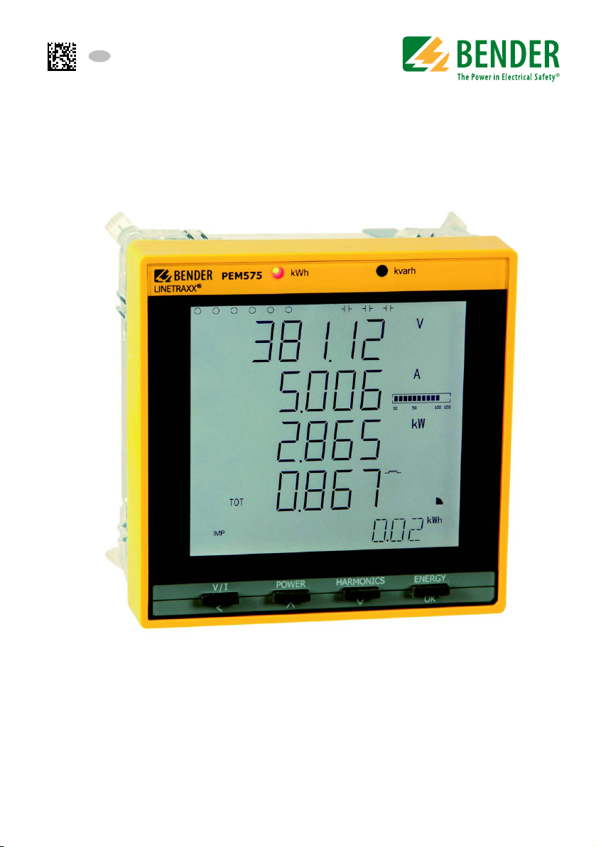
Bender LINETRAXX PEM575, LINETRAXX PEM575-251, LINETRAXX PEM575-455, LINETRAXX PEM575-451 Series Manual
Manual
EN
PEM575
B 9310 0575
B 9310 0576
B 9310 0577
B 9310 0578
Universal measuring device
Software version 2.00.xx
PEM575_D00016_00_M_XXEN/04.2015

Bender GmbH & Co. KG
Londorfer Str. 65 • 35305 Gruenberg • Germany
Postfach 1161 • 35301 Gruenberg • Germany
© Bender GmbH & Co. KG
Tel.: +49 6401 807-0
Fax: +49 6401 807-259
E-Mail: info@bender.de
www.bender.de
All rights reserved.
Reprinting only with permission
of the publisher. Subject to change!
Photos: Bender and bender systembau archives.

Table of Contents
1. Making effective use of this document ............................................... 9
1.1 How to use this manual ......................................................................................... 9
1.2 Technical support: Service and support ........................................................ 10
1.3 Workshops ............................................................................................................... 11
1.4 Delivery conditions, guarantee, warranty and liability ............................ 11
2. Safety ...................................................................................................... 13
2.1 Intended use ........................................................................................................... 13
2.2 Qualified personnel .............................................................................................. 13
2.3 General safety instructions ................................................................................ 14
3. Device description ............................................................................... 15
3.1 Area of application ................................................................................................ 15
3.2 Device features ....................................................................................................... 15
3.3 Versions .....................................................................................................................16
3.4 Application example ............................................................................................ 17
3.5 Description of function ....................................................................................... 17
3.6 Front view and rear view .................................................................................... 18
4. Installation and connection ............................................................... 19
4.1 Project planning ..................................................................................................... 19
4.2 Safety instructions ................................................................................................. 19
4.3 Installing the device ............................................................................................. 19
4.3.1 Dimension diagrams ................................................................................... 19
4.3.2 Front panel mounting ................................................................................ 20
4.4 Connection of the device ................................................................................... 21
4.4.1 Safety information ....................................................................................... 21
4.4.2 Back-up fuses ................................................................................................. 21
4.4.3 Connection of measuring current transformers ............................... 21
PEM575_D00016_00_M_XXEN/04.2015
3

Table of Contents
4.5 Instructions for connection ................................................................................ 21
4.6 Wiring diagram ....................................................................................................... 22
4.7 Connection diagram voltage inputs ............................................................... 23
4.7.1 Three-phase 4-wire system (TN, TT, IT system) .................................. 23
4.7.2 Three-phase 3-wire system ....................................................................... 25
4.7.3 Connection via voltage transformers ................................................... 26
4.8 Digital inputs ........................................................................................................... 26
4.9 Digital outputs ........................................................................................................ 27
4.10 Modbus TCP (connector pin assignment) .................................................... 27
5. Commissioning ...................................................................................... 29
5.1 Check proper connection ................................................................................... 29
5.2 Before switching on .............................................................................................. 29
5.3 Switching on ............................................................................................................ 29
5.4 System .......................................................................................................................30
6. Operation ............................................................................................... 31
6.1 Getting to know the operating elements .................................................... 31
6.2 LCD testing ............................................................................................................... 32
6.3 Getting to know standard display areas ....................................................... 33
6.4 Power and current demands (demand display) ......................................... 36
6.5 LED indication ......................................................................................................... 37
6.6 Standard display .................................................................................................... 37
6.7 Data display ............................................................................................................. 37
6.7.1 "V/I" button ..................................................................................................... 38
6.7.2 "POWER"button ............................................................................................ 40
6.7.3 "HARMONICS" button ................................................................................. 42
6.7.4 "ENERGY" button .......................................................................................... 43
6.8 Setup configuration via the front panel ........................................................ 44
6.8.1 Setup: Function of buttons ....................................................................... 44
6.8.2 Setup: Overview diagram menu ............................................................. 45
6.9 Setup: adjustment possibilities ........................................................................ 46
6.10 Configuration example: ....................................................................................... 52
4
PEM575_D00016_00_M_XXEN/04.2015

Table of Contents
7. Application/inputs and outputs ......................................................... 53
7.1 Digital inputs (DI) ................................................................................................... 53
7.2 Digital outputs (DO) ............................................................................................. 53
7.3 Energy pulsing output ......................................................................................... 54
7.4 Power and energy ................................................................................................. 54
7.4.1 Basic measurements ................................................................................... 54
7.4.2 High-speed measurements ...................................................................... 55
7.4.3 Voltage and current phase angles ......................................................... 55
7.4.4 Energy .............................................................................................................. 55
7.5 Demand DMD ......................................................................................................... 55
7.5.1 Max/Min values per demand period ..................................................... 57
7.6 Setpoints ................................................................................................................... 57
7.7 Logic modules ........................................................................................................ 61
8. Logging ................................................................................................... 63
8.1 Peak demand log ................................................................................................... 63
8.2 Max/Min log ............................................................................................................. 63
8.3 Data recorder (DR) ................................................................................................. 65
8.3.1 Setup parameters ......................................................................................... 65
8.3.2 Selectable measured quantities for data recorders DR .................. 66
8.4 Energy log ................................................................................................................ 78
8.5 Waveform recording (WFR) ................................................................................ 79
8.6 Power Quality log (PQ log) ................................................................................. 81
8.7 Event log (SOE log) ................................................................................................ 81
9. Power Quality ........................................................................................ 83
9.1 Fundamentals ......................................................................................................... 83
9.2 Harmonic distortion .............................................................................................. 83
9.3 Deviation from the pre-set nominal value (
9.4 Undervoltage/overvoltage setpoint (sag/swell setpoint) ...................... 85
9.5 Transient events setpoint ................................................................................... 86
9.6 Time synchronisation ........................................................................................... 86
9.7 E-mail notification ................................................................................................. 87
5
ΔU, Δ
❆) ................................... 85
PEM575_D00016_00_M_XXEN/04.2015

Table of Contents
10. Modbus Register Map ........................................................................ 89
10.1 Basic measurements ............................................................................................. 91
10.2 Energy measurement ........................................................................................... 96
10.3 Pulse counter .......................................................................................................... 98
10.4 Fundamental measurements (Power quality) ............................................. 98
10.5 Harmonic measurements (Power quality) ................................................. 100
10.6 High-speed measurement .............................................................................. 102
10.7 Demand .................................................................................................................. 104
10.7.1 Present demand ........................................................................................ 104
10.7.2 Predicted demand .................................................................................... 106
10.7.3 Maximum values per demand period ............................................... 108
10.7.4 Minimum values per demand period ................................................ 110
10.7.5 Peak demand of this month .................................................................. 112
10.7.6 Peak demand last month ....................................................................... 112
10.7.7 Peak demand data structure ................................................................. 113
10.8 Max/Min log .......................................................................................................... 114
10.8.1 Maximum values of this month .......................................................... 114
10.8.2 Min log of this month .............................................................................. 116
10.8.3 Max log of last month .............................................................................. 118
10.8.4 Min log last month .................................................................................... 120
10.8.5 Max/Min log data structure ................................................................... 121
10.9 Setup parameters ............................................................................................... 122
10.10 Clear/reset register ............................................................................................. 128
10.11 Setpoint setup parameters ............................................................................. 130
10.11.1 Structure of the setpoint register (standard) .................................. 131
10.11.2 Setpoint register structure (high speed) ........................................... 131
10.12 Logic module ....................................................................................................... 134
10.12.1 Logic module registers ............................................................................ 134
10.12.2 Logic module data structure ................................................................. 134
10.13 Data recorder (DR) .............................................................................................. 136
10.13.1 Data recorder register .............................................................................. 136
10.13.2 High-speed data recorder register structure .................................. 138
10.13.3 Standard data recorder register structure ....................................... 140
10.14 Waveform recording (WFR) ............................................................................. 141
6
PEM575_D00016_00_M_XXEN/04.2015

Table of Contents
10.15 Energy log ............................................................................................................. 144
10.16 PQ log ..................................................................................................................... 146
10.17 Event log (SOE log) ............................................................................................. 148
10.17.1 Energy log register .................................................................................... 148
10.17.2 Event log data structure ......................................................................... 149
10.17.3 Event classification (SOE log) ............................................................... 150
10.18 Time setting .......................................................................................................... 159
10.19 DOx output control ........................................................................................... 159
10.20 Universal measuring device information ................................................... 161
11. Technical data .................................................................................. 163
11.1 Standards and certifications ........................................................................... 165
11.2 Ordering information ........................................................................................ 165
INDEX ......................................................................................................... 167
7
PEM575_D00016_00_M_XXEN/04.2015

1. Making effective use of this document
DANGER
WARNING
CAUTION
1.1 How to use this manual
This manual is aimed at qualified personnel in electrical engineering and communica-
tions technology,
encing in the immediate vicinity of the device.
To make it easier for you to understand and revisit certain sections of text and instructions in the manual, we have used symbols to identify important instructions and information. The meaning of these symbols is explained below:
installers and users of the product and must be kept ready for refer-
The signal word indicates that there is a high risk of danger,, that will
result in death or serious injury if not avoided.
This signal word indicates a medium risk of danger that can lead to
death or serious injury if not avoided.
This signal word indicates a low level risk that can result in minor or
moderate injury or damage to property if not avoided.
This symbol denotes information intended to assist the user in making
optimum use of the product.
Although great care has been taken in the drafting of this operating manual, it may nevertheless contain errors and mistakes. Bender cannot accept any liability for injury to
persons or damage to property resulting from errors or mistakes in this manual.
Each of the registered trademarks which appears in this document remains the
property of its owner.
PEM735_D00084_00_M_XXEN/02.2015
9

Making effective use of this document
1.2 Technical support: Service and support
For commissioning and troubleshooting Bender offers you:
First level support
Technical support by phone or e-mail for all Bender products
All questions about customer applications
Commissioning
Troubleshooting
Phone: +49 6401 807-760*
Fax: +49 6401 807-259
only available in Germany: 0700BenderHelp (Tel. and Fax)
E-mail: support@bender-service.com
Repair service
Repair, calibration, update and replacement service for all Bender products
Repair, calibration, testing and analysing Bender products
Hardware and software update for Bender devices
Delivery of replacement devices for faulty or incorrectly delivered Bender devices
Extended warranty for Bender devices with in-house repair service resp. replace-
ment devices at no extra cost
Phone: +49 6401 807-780** (technical issues)
+49 6401 807-784**, -785** (commercial matters)
Fax: +49 6401 807-789
E-mail: repair@bender-service.com
Please send the devices for repair to the following address:
Bender GmbH, Repair Service
Londorfer Strasse 65
35305 Gruenberg, Germany
10
PEM735_D00084_00_M_XXEN/02.2015

Making effective use of this document
Field service
On-site service for all Bender products
Commissioning, parameter setting, maintenance, trouble shooting for Bender
products
Analysis of the electrical installation in the building (power quality test, EMC test,
thermography)
Practical training courses for customers
Phone: +49 6401 807-752**, -762 **(technical issues)
+49 6401 807-753** (commercial matters)
Fax: +49 6401 807-759
E-mail: fieldservice@bender-service.com
Internet: www.bender.de.
*Available from 7.00 a.m. to 8.00 p.m. on 365 days of the year (CET/UTC+1)
**Mo-Thu 7.00 a.m. - 8.00 p.m., Fr 7.00 a.m. - 13.00 p.m.
1.3 Workshops
Bender would be happy to provide training in respect of the use of the universal
measuring device.
Current dates of training courses and workshops can be found on the Internet at
www.bender.de -> Know-how -> Seminars.
1.4 Delivery conditions, guarantee, warranty and liability
The conditions of sale and delivery set out by Bender apply.
For software products, the "Softwareklausel zur Überlassung von Standard- Software als Teil von Lieferungen, Ergänzung und Änderung der Allgemeinen Lieferbedingungen für Erzeugnisse und Leistungen der Elektroindustrie" (software clause
in respect of the licensing of standard software as part of deliveries, modifications
and changes to general delivery conditions for products and services in the electrical industry) set out by the ZVEI (Zentralverband Elektrotechnik- und Elektronikindustrie e.V., (German Electrical and Electronic Manufacturers' Association) also
applies.
Conditions of sale and delivery can be obtained from Bender in printed or
electronic format.
PEM735_D00084_00_M_XXEN/02.2015
11

Making effective use of this document
12
PEM735_D00084_00_M_XXEN/02.2015

2. Safety
2.1 Intended use
The universal measuring device PEM575 is suitable for
the analysis of energy and power
monitoring of the power supply quality
data recording for energy management.
As a compact device for front panel mounting, it is a replacement for analogue indicating instruments. Das PEM575 is suitable for 2, 3 and 4-wire systems and can be
used in TN, TT and IT systems. The current measurement inputs of the PEM are connected via external ../1 A or ../5 A measuring current transformers. In principle, measurements in medium and high voltage systems are carried out via measurement
transformers and voltage transformers.
Use for the intended purpose also includes:
Device-specific settings according to local equipment and operating conditions.
The observation of all information in the operating manual.
2.2 Qualified personnel
Only electrically skilled persons are authorised to install and commission this device.
Electrically skilled persons are those who have the relevant education, knowledge
and experience, as well as knowledge of the relevant safety standards and who are
able to perceive risks and to avoid hazards which electricity can create when work
activities are carried out on electrical installations. The electrically skilled person is
specially trained for carrying out work activities in his specific working environment
and has a thorough knowledge of the relevant standards and regulations. In Germany, an electrically skilled person must meet the requirements of the accident
prevention regulation BGV A3. In other countries the applicable regulations have
to be observed and followed.
PEM735_D00084_00_M_XXEN/02.2015
13

Safety
DANGER
2.3 General safety instructions
Bender devices are designed and built in accordance with the state of the art and
accepted rules in respect of technical safety. However, the use of such devices may
introduce risks to the life and limb of the user or third parties and/or result in damage to Bender equipment or other property.
Danger of electric shock!
Touching live parts will cause danger of electric shock with fatal
consequences.
All work activities on electrical installations as well as installation
activities, commissioning activities and work activities with the device in
operation may only be carried out by electrically skilled persons!
Only use Bender equipment:
– as intended
– in perfect working order
– in compliance with the accident prevention regulations and guidelines appli-
cable at the location of use
Eliminate all faults immediately which may endanger safety.
Do not make any unauthorised changes and only use replacement parts and opti-
onal accessories purchased from or recommended by the manufacturer of the
equipment. Failure to observe this requirement can result in fire, electric shock
and injury.
Information plates must always be clearly legible. Replace damaged or illegible
plates immediately.
If the device is overloaded by overvoltage or a short-circuit current load, it must
be checked and replaced if necessary.
If the device is being used in a location outside the Federal Republic of Germany,
the applicable local standards and regulations must be complied with.
European standard EN 50110 can be used as a guide.
14
PEM735_D00084_00_M_XXEN/02.2015

3. Device description
3.1 Area of application
For humans, electric current is not immediately visible. Universal measuring devices for monitoring electrical parameters are used wherever energy consumption,
performance measurements or the quality of the supply voltage are to be made visible.
The PEM575 is suitable for monitoring
power generation systems (PV systems, CHPs, hydro power and wind power
plants)
energy-intensive equipment and parts of installation
sensitive equipment
3.2 Device features
The universal measuring device PEM575 for power quality and energy management is characterised by the following features:
Accuracy class in accordance withIEC 62053-22: 0.2 S
Password protection
16 programmable setpoints
LED pulse outputs for active and reactive energy
Modbus RTU communication via RS-485 interface
6 digital inputs
3 digital outputs
Power and current demands for particular time frames
Peak demands with timestamps
Individual, current/voltage harmonics up to the 63
Max and Min values
High-resolution waveform recording (12.8 kHz)
Data recorder
Event log: 512 events, setup changes, setpoint alarming, DI status changes, DO
switching operations
Sag/swell detection
Detection of transient events
Communication:
rd
harmonic
PEM735_D00084_00_M_XXEN/02.2015
15

– Galvanically isolated RS-485 interface (1,200 … 19,200 bit/s)
– Modbus/RTU protocol
– Modbus/TCP (10/100 Mbit/s)
Measured quantities
– Phase voltages U
– Line-to-line voltages U
– Phase currents I
– Neutral current (calculated) I
– Neutral current (measured) I
, UL2, U
L1
, U
L1L2
, I2, I3 in A
1
in A
0
in A
4
L2L3
L3
in V
, U
– Frequency f in Hz
– Phase angle for U and I in °
– Power per phase conductor P in kW, Q in kvar, S in kVA
– Total power P in kW, Q in kvar, S in kVA
– Displacement factor cos (φ)
– Power factor λ
– Active and reactive energy import in kWh, kvarh
– Active and reactive energy export in kWh, kvarh
– Voltage unbalance in %
– Current unbalance in %
– Harmonic distortion
(THD, TOHD, TEHD) for U and I
– K-factor for I
L3L1
Device description
in V
3.3 Versions
PEM575 230/400 V;
Current input 5 A
PEM575-251 230/400 V
Current input 1 A
PEM575-455 400/690 V, 50 Hz
Current input 5 A
PEM575-451 400/690 V, 50 Hz
Current input 1 A
16
PEM735_D00084_00_M_XXEN/02.2015
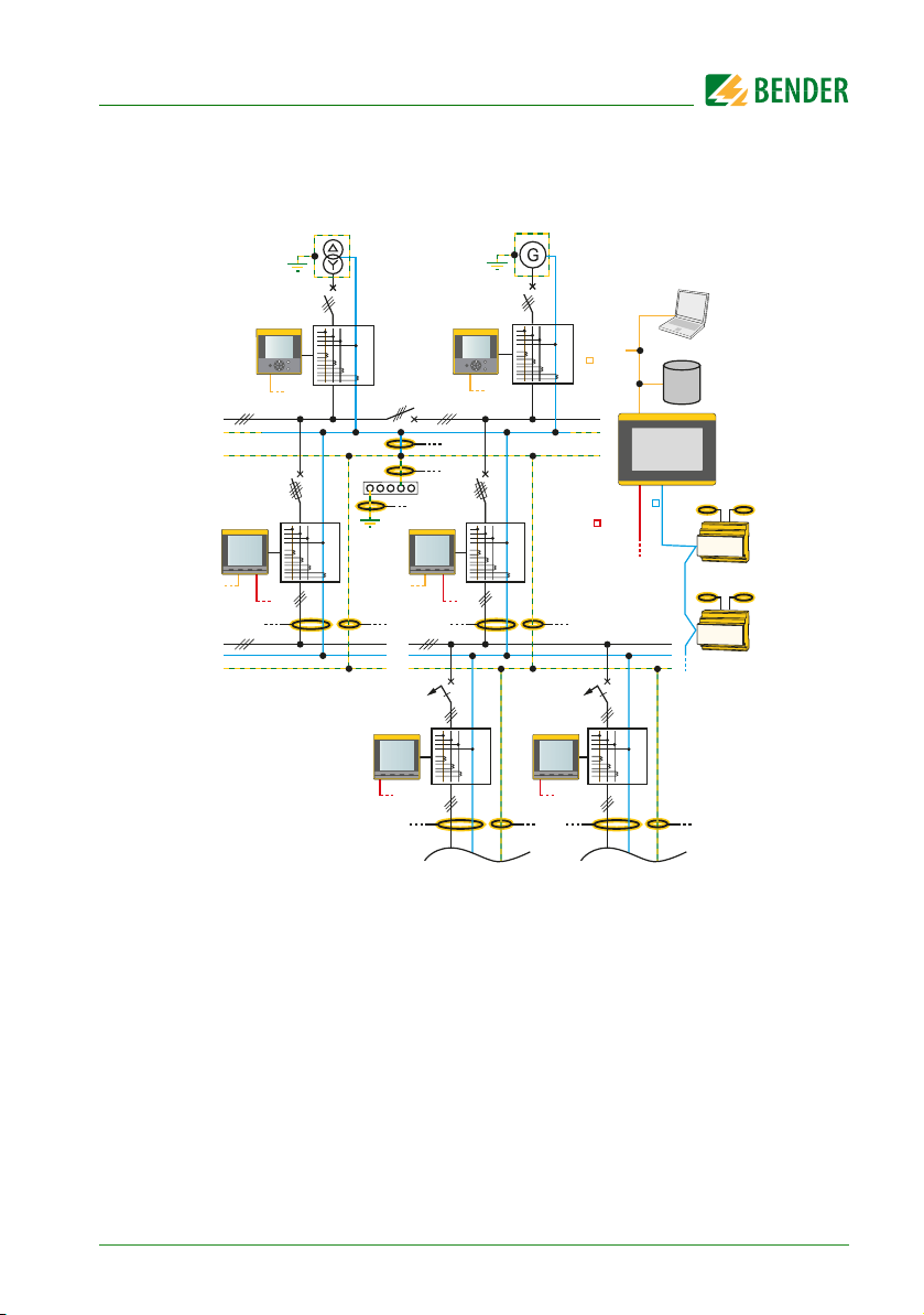
3.4 Application example
PEM7xx
Modbus TCP
L
PEN
PE
PEM5xx PEM5xx
Modbus TCP
Modbus RTU
L
N
PE
U
I
U
I
UV1
PEM3xx
Fig. 3.1: Application example
Modbus TCP
Modbus RTU
Modbus RTU
PAS
PEM7xx
Modbus TCP
3
U
Ethernet
I
NSHV
CP700
Modbus
U
I
PEM3xx
U
I
Modbus RTU
RTU
3
U
I
UV2
BMS
Datenbank
1…12
RCMS
1…12
RCMS
3.5 Description of function
The digital universal measuring device PEM575 is suited for measuring and displaying electrical quantities of a public electricity network. The PEM575 is able to perform current, voltage, energy consumption and performance measurements as
well as displaying individual harmonic components of current and voltage for assessment of the voltage and current quality.
PEM735_D00084_00_M_XXEN/02.2015
17
Device description
The accuracy of the active energy metering corresponds to class 0.2 S in compliance with the DIN EN 62053-22 (VDE 0418 Part 3-22):2003-11.
The large display of the panel mounting device makes the relevant measured
quantities easily legible and enables fast configuration. In addition, the RS-485 interface allows a central evaluation and processing of data. Switching operations
can be monitored or initiated via the digital inputs and outputs (Example: Switching off uncritical loads if the peak load limit value is exceeded).
The universal measuring device PEM575 provides the following functions:
Provision of energy consumption data for a well-thought-out energy manage-
ment
Allocation of energy costs
Power quality monitoring for cost reduction and increased plant availability
High-resolution waveform recording allow analysis of power quality phenomena
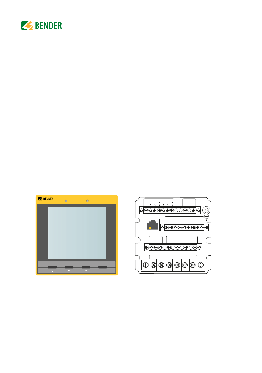
3.6 Front view and rear view
The connecting terminals are located at the rear of the device.
18
LINETRAXX®
PEM575
V/I
kWh
POWER HARMONICS
kvarh
ENERGY
OK
DIC DI1 DI2 DI3 DI4 DI5 DI6
• l41
• l11
Fig. 3.2: Front view (left) and rear view (right) PEM575
PEM735_D00084_00_M_XXEN/02.2015
RS-485ETH
D
D+
l42SH
L1 L2 L3 N
l12
• l21 • l31
A1 A2
DO34 DO33 DO24 DO23 DO14 DO13
-
SH
l22 l32
Power
4. Installation and connection
DANGER
4.1 Project planning
For any questions associated with project planning, please contact Bender:
Internet: www.bender.de
Tel.: +49-6401-807-0
4.2 Safety instructions
Only electrically skilled persons are allowed to connect and commission the device.
Such persons must have read this manual and understood all instructions relating
to safety.
Danger of electric shock!
Follow the basic safety rules when working with electricity.
Consider the data on the rated voltage and supply voltage as specified
in the technical data!
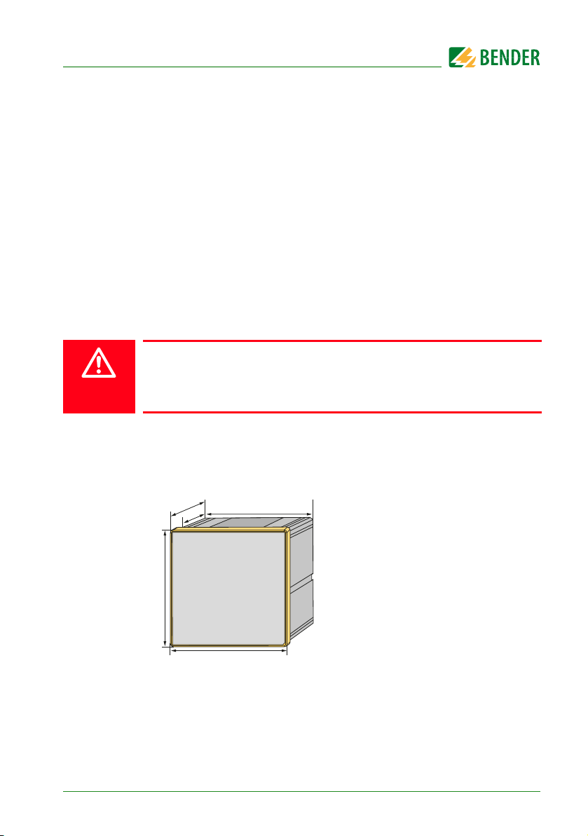
4.3 Installing the device
4.3.1 Dimension diagrams
106
88
96
96
Fig. 4.1: Dimension diagram PEM575 (front view)
PEM735_D00084_00_M_XXEN/02.2015
91
19
Installation and connection
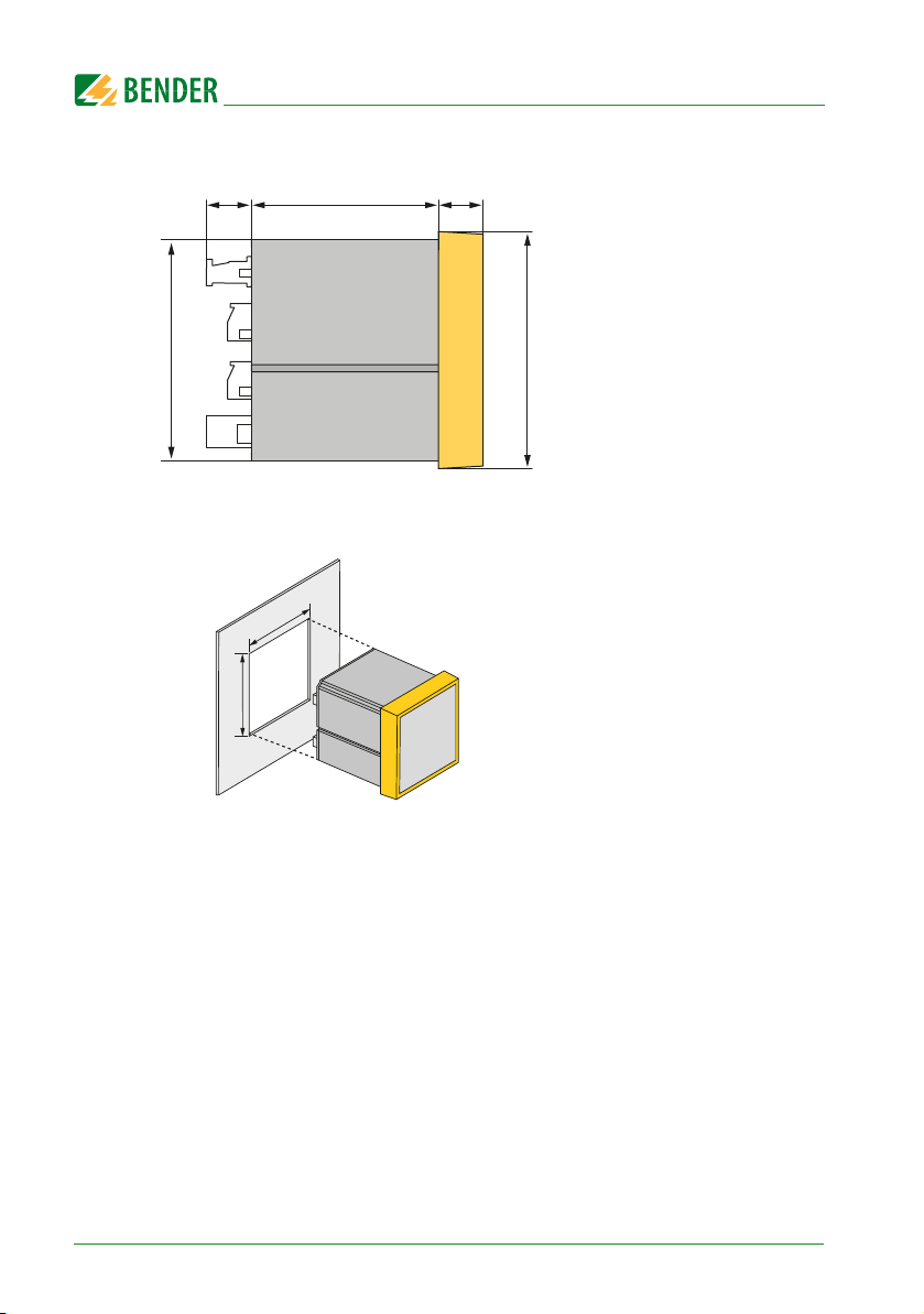
18 88
91
Fig. 4.2: Dimension diagram PEM575 (side view)
92
92
Fig. 4.3: Dimension diagram PEM575 (panel cutout)
18
96
4.3.2 Front panel mounting
A front panel cutout of 92 mm x 92 mm is necessary for installation.
1. Insert the device through the cutout in the front panel.
2. Insert the two installation clips into the equipment rail from behind.
3. Push the clips towards the front panel and tighten the associated screws by
hand.
4. Check the device to ensure that it is firmly installed in the front panel.
The device is installed.
20
PEM735_D00084_00_M_XXEN/02.2015

Installation and connection
DANGER
4.4 Connection of the device
4.4.1 Safety information
Danger of electric shock!
Follow the basic safety rules when working with electricity.
Consider the data on the rated voltage and supply voltage as specified
in the technical data!
4.4.2 Back-up fuses
Back-up fuse supply voltage: 6 A
Short-circuit protection Protect the measuring inputs according to the require-
ments of the standards. (Recommendation: 2 A). A suitable isolation means must
be provided. For details refer to the operating manuals of the measuring current
transformers currently used.
If the supply voltage Us is supplied by an IT system, both lines are to be
protected.
4.4.3 Connection of measuring current transformers
When connecting the measuring current transformers it is important to consider
the requirements of DIN VDE 0100-557 (VDE 0100-557) –
Low voltage installations - Part 5: Selection and erection of electrical equipment Section 557: Auxiliary circuits.
4.5 Instructions for connection
Connect the PEM575 to the supply voltage (terminals A1 and A2 resp. +/-). Con-
nect terminal " " to the protective conductor.
Power protection by a 6 A fuse, quick response. If being supplied from an IT sys-
tem, both lines have to be protected by a fuse.
Connection to the RS-485 bus is made via the terminals D+, D- and SH. Up to 32
devices can be connected to the bus. The maximum cable length for the bus connection of all devices is 1200 m.
PEM735_D00084_00_M_XXEN/02.2015
21
Installation and connection
2
3
4
7
5
6
1
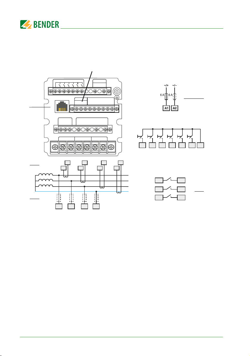
4.6 Wiring diagram
Connect the device according the wiring diagram. The connections are located at
the rear of the device.
DIC DI1 DI2 DI3 DI4 DI5 DI6
RS-485ETH
D+
• l41
l42SH
L1 L2 L3 N
• l11
l12
• l21 • l31
I12
I11
L1 L2 L3 N
DO34 DO33 DO24 DO23 DO14 DO13
D
-
SH
l22 l32
I22
I21
Power
A1 A2
I32
I31
I42
I41
Fig. 4.4: Wiring diagram
DI1 DICDI5 DI6DI2 DI3 DI4
L1
L2
L3
N
U
S
DO13 DO14
DO23 DO24
DO33 DO34
22
PEM735_D00084_00_M_XXEN/02.2015

Installation and connection
Legend to wiring diagram
Connection RS-485 bus
1
Supply voltage. Power protection by a 6 A fuse, quick response. If
2
being supplied from an IT system, both lines have to be
protected by a fuse.
Digital inputs
3
Digital outputs (N/O contacts)
4
Measuring voltage inputs: The measuring leads should be
5
protected with appropriate fuses.
Connection to the system to be monitored
6
Connection Modbus TCP
7
4.7 Connection diagram voltage inputs
4.7.1 Three-phase 4-wire system (TN, TT, IT system)
The universal measuring device PEM575 can be used in three-phase-4-wire sys-
PEM735_D00084_00_M_XXEN/02.2015
23
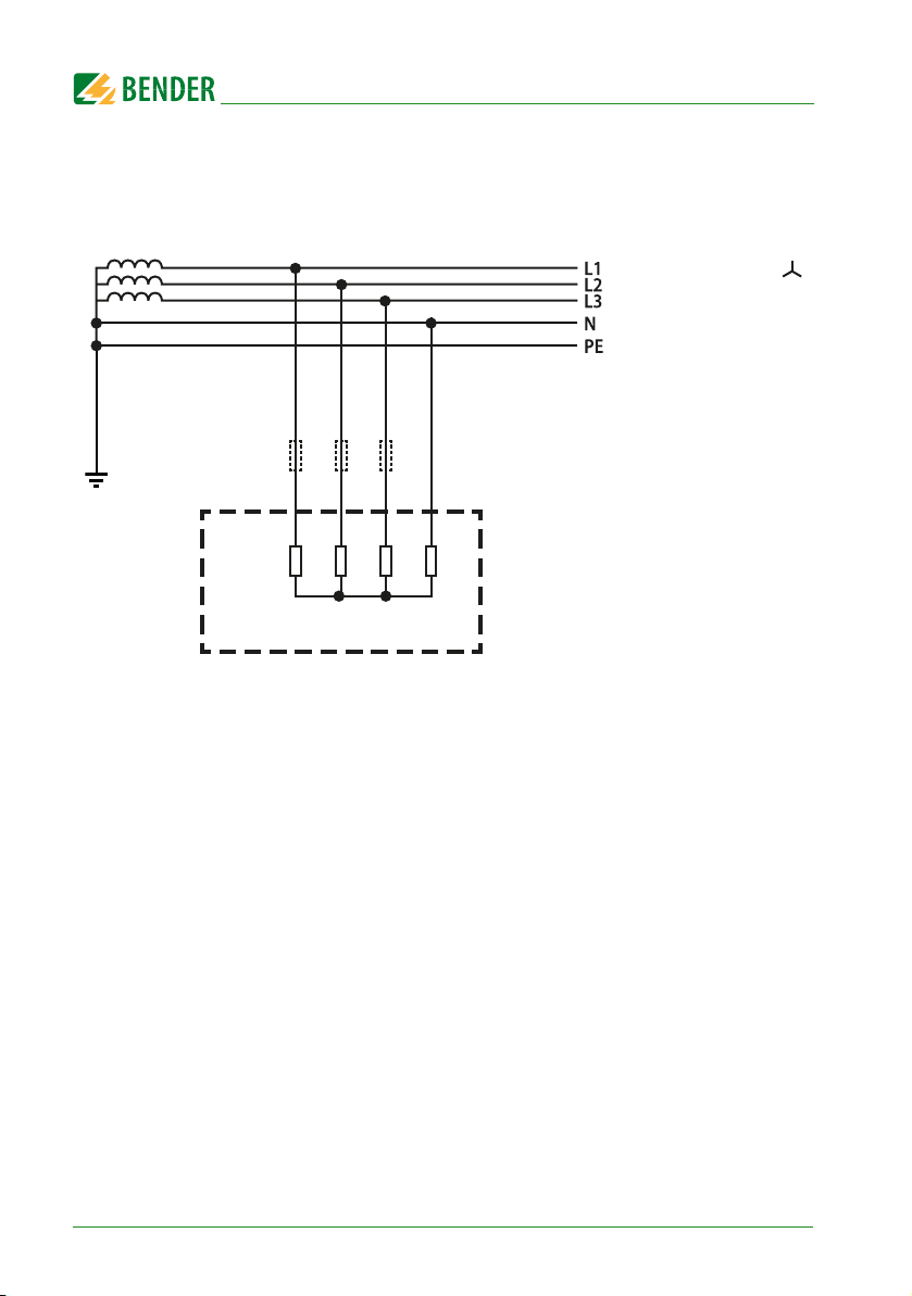
Installation and connection
tems, independent of the type of distribution system (TN, TT, IT system).
AC 400 V / 230 V
L1
R
i
L2
L3
N
PEM
Fig. 4.5: Connection diagram three-phase 4-wire system
(e.g. TN-S system)
24
PEM735_D00084_00_M_XXEN/02.2015
Installation and connection
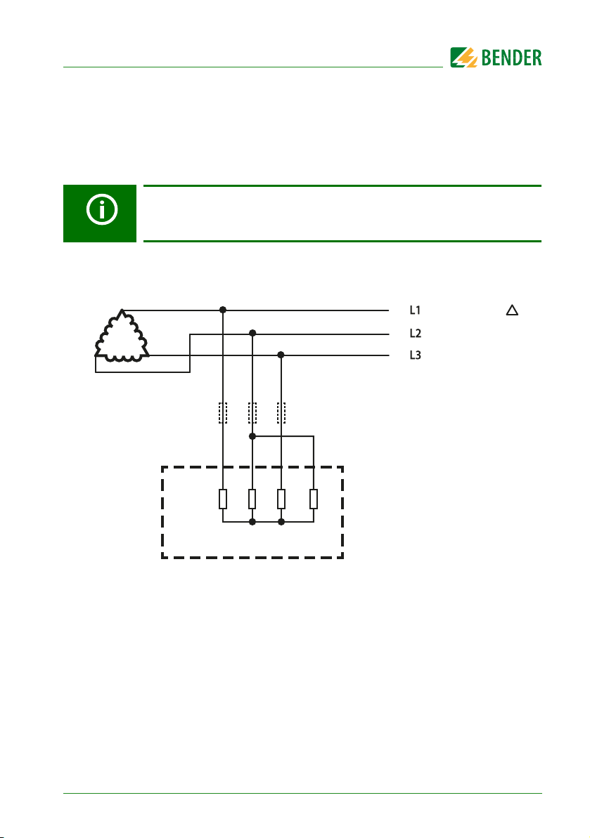
4.7.2 Three-phase 3-wire system
The universal measuring device PEM575 can be used in three-phase-3-wire systems.
The line voltage must not exceed AC 400 V.
When used in 3-wire systems, the connection type (TYPE) has to be set to
DELTA (refer to page 46). For this purpose, the measuring inputs L2 and
N are to be bridged.
AC 400 V
L1
R
i
PEM
Fig. 4.6: Connection diagram three-phase-3-wire system
PEM735_D00084_00_M_XXEN/02.2015
L2
L3
N
25

Installation and connection
V
4.7.3 Connection via voltage transformers
The coupling via voltage transformers allows the use of the measuring device in
medium and high voltage systems.
The transformation ratio can be adjusted in the PEM575 (1…2200).
LV / MV / H
L1
R
i
L2
L3
N
PEM
Fig. 4.7: Connection diagram 3-wire system via voltage transformers
4.8 Digital inputs
The universal measuring device PEM575 provides 6 digital inputs. The inputs are
supplied by a galvanically isolated DC 24 V voltage. An external circuit providing at
least a current of I
> 2.4 mA is required for triggering the inputs.
min
DI1 DICDI5 DI6DI2 DI3 DI4
26
PEM735_D00084_00_M_XXEN/02.2015
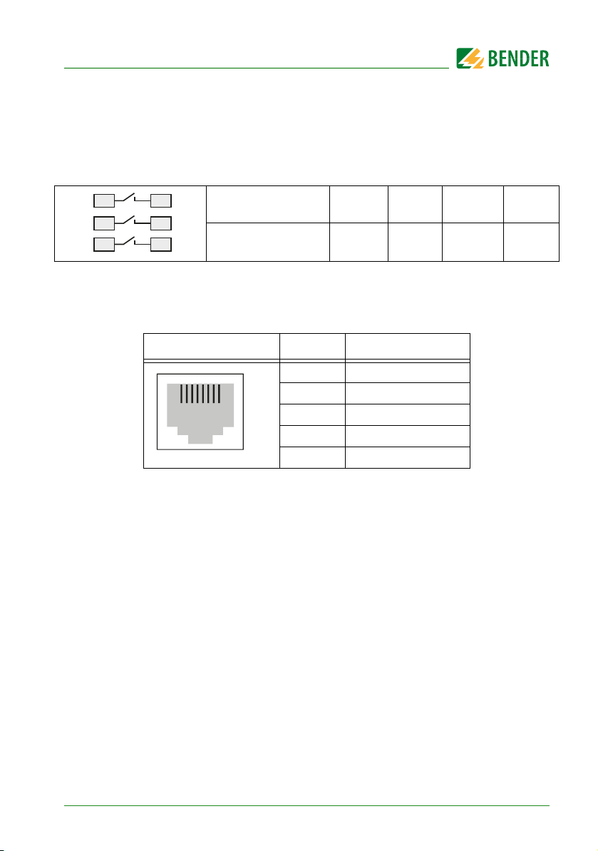
4.9 Digital outputs
The universal measuring device PEM575 features 3 configurable outputs
(N/O contact).
DO13 DO14
DO23 DO24
DO33 DO34
Rated operational
voltage
Rated
operational current
AC 230 V DC 24 V AC 110 V DC 12 V
5 A 5 A 6 A 5 A
4.10 Modbus TCP (connector pin assignment)
RJ45 Pin assignment
1 Transmit Data +
2 Transmit Data –
12345678
3 Receive Data +
4, 5, 7, 8 not used
6 Receive Data –
PEM735_D00084_00_M_XXEN/02.2015
27

Installation and connection
28
PEM735_D00084_00_M_XXEN/02.2015

5. Commissioning
5.1 Check proper connection
Observe the relevant standards and regulations that have to be observed for installation and connection as well as the operating manual of the respective device.
5.2 Before switching on
Before switching on think carefully about these questions:
1. Does the connected supply voltage correspond to the nameplates' information?
2. Are you sure that the nominal insulation voltage of the measuring current
transformer has not been exceeded?
3. Does the measuring current transformer's maximum current correspond to
the nameplate information of the connected device?
5.3 Switching on
After switching on, proceed as follows:
1. Connect the supply voltage.
2. Set the bus address/IP address.
3. Set the CT transformation ratio (for each channel).
4. Change the measuring current transformer's counting direction, if required.
5. Set the nominal voltage (line-to-line voltage U
6. Select wye connection or delta connection.
).
LL
PEM735_D00084_00_M_XXEN/02.2015
29

Commissioning
5.4 System
The universal measuring device PEM575 can be programmed and queried via Modbus RTU. For details refer to „chapter 10. Modbus Register Map“ or the Internet
www.modbus.org.
In addition, it is possible to integrate the device into Bender's own BMS (Bender
measuring device interface) bus protocol via additional communication modules.
In this way, communication with (already existing) Bender devices for device parameterisation and visualisation of measured values and alarms can be achieved.
Help and examples of system integration can be found on the Bender homepage
www.bender.de or you can contact our Bender Service for personal advice (see
„chapter 1.2 Technical support: Service and support“).
30
PEM735_D00084_00_M_XXEN/02.2015
 Loading...