

Bender LINETRAXX PEM555 Quick Start Manual
Quick start: PEM555
Quick start
LINETRAXX®
PEM555
This short operating instruction does not replace the manual!
You will find the manual on the website
www.bender.de
Make sure that the personnel has read this manual and understood all instructions relating to safety.
V/I
Intended use Scope of delivery
The universal measuring device PEM555 is suitable for
● the analysis of energy and power (Power Analyzer)
● monitoring of the power supply quality (Power Quality)
● data recording for energy management (Energy Manage-
ment).
As a compact device for front panel mounting, it is suitable to replace analogue indicating instruments. The PEM555 is suitable for
3 and 4-wire systems and can be used in TN, TT and IT systems.
The current measurement inputs of the PEM are connected via
external ../1 A or ../5 A measuring current transformers.
Measurement in medium and high-voltage systems are principally carried out using measuring current and voltage transformers.
The accuracy of the active energy metering corresponds to class
0.2 S in compliance with the DIN EN 62053-22 (VDE 0418 Part 3-
22):2003-11.
● 1 PEM555
● Safety instructions
● This short operating instructions
● 1 sealing frame "IP54"
Safety instruction
Danger of electric shock!
Follow the basic safety rules when working with electricity.
Consider the data on the rated voltage and supply voltage as
specified in the technical data!
kWh
POWER HARMONICS
kvarh
ENERGY
OK
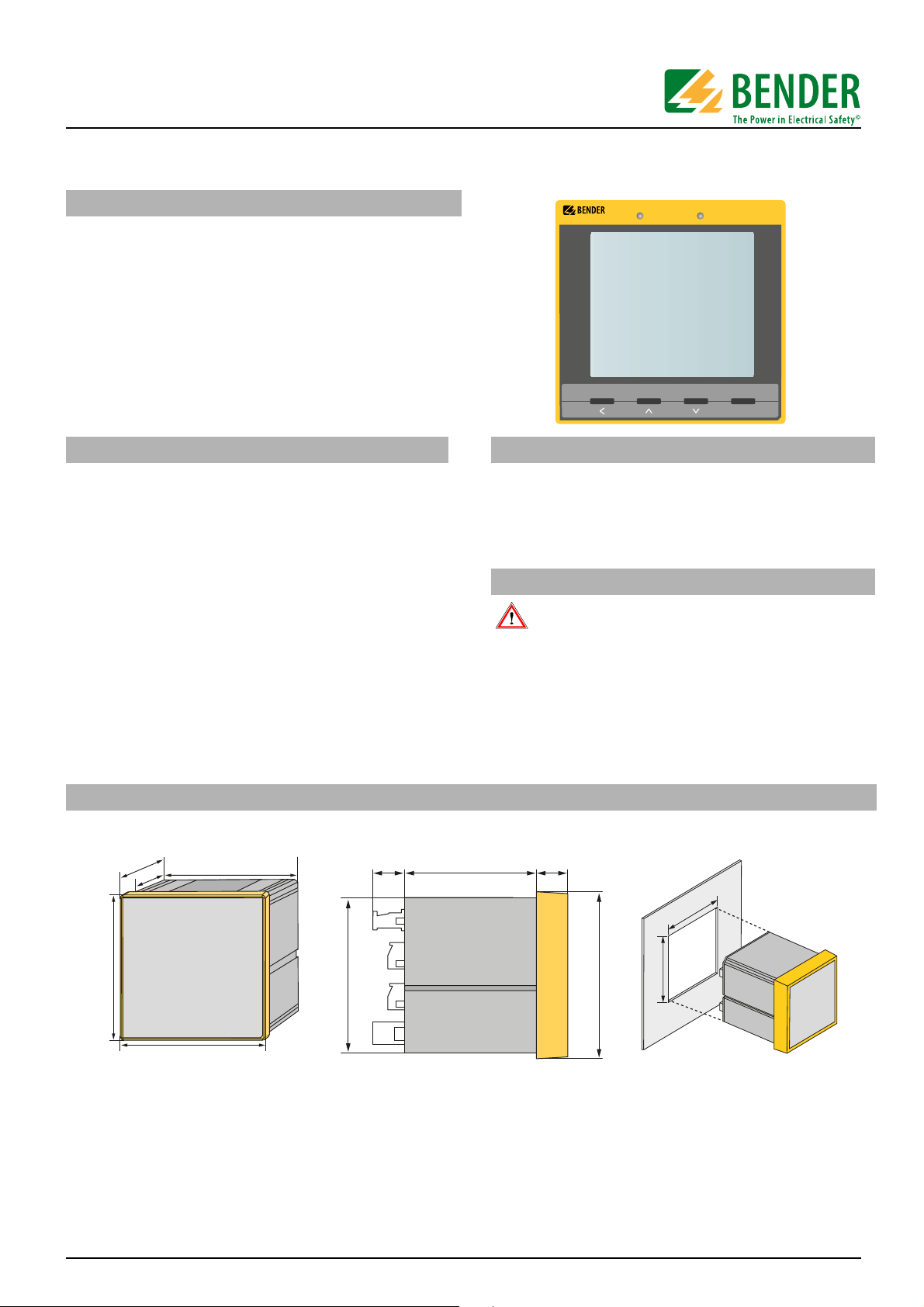
Installing the device
Front-panel mounting (front view, side view, panel cutout)
106
88
96
91
91
96
A front-panel cutout of 92 mm x 92 mm is required for the device.
1. Insert the device into the installation opening of the front panel.
2. Insert the two installation clips into the equipment rail from behind.
3. Push the installation clips towards the front panel and tighten the screws by hand.
4. Check the device to ensure that it is firmly mounted in the front panel.
18 88
18
92
96
92
PEM555_D00016_00_Q_XXEN/04.2014
1
Quick start: PEM555
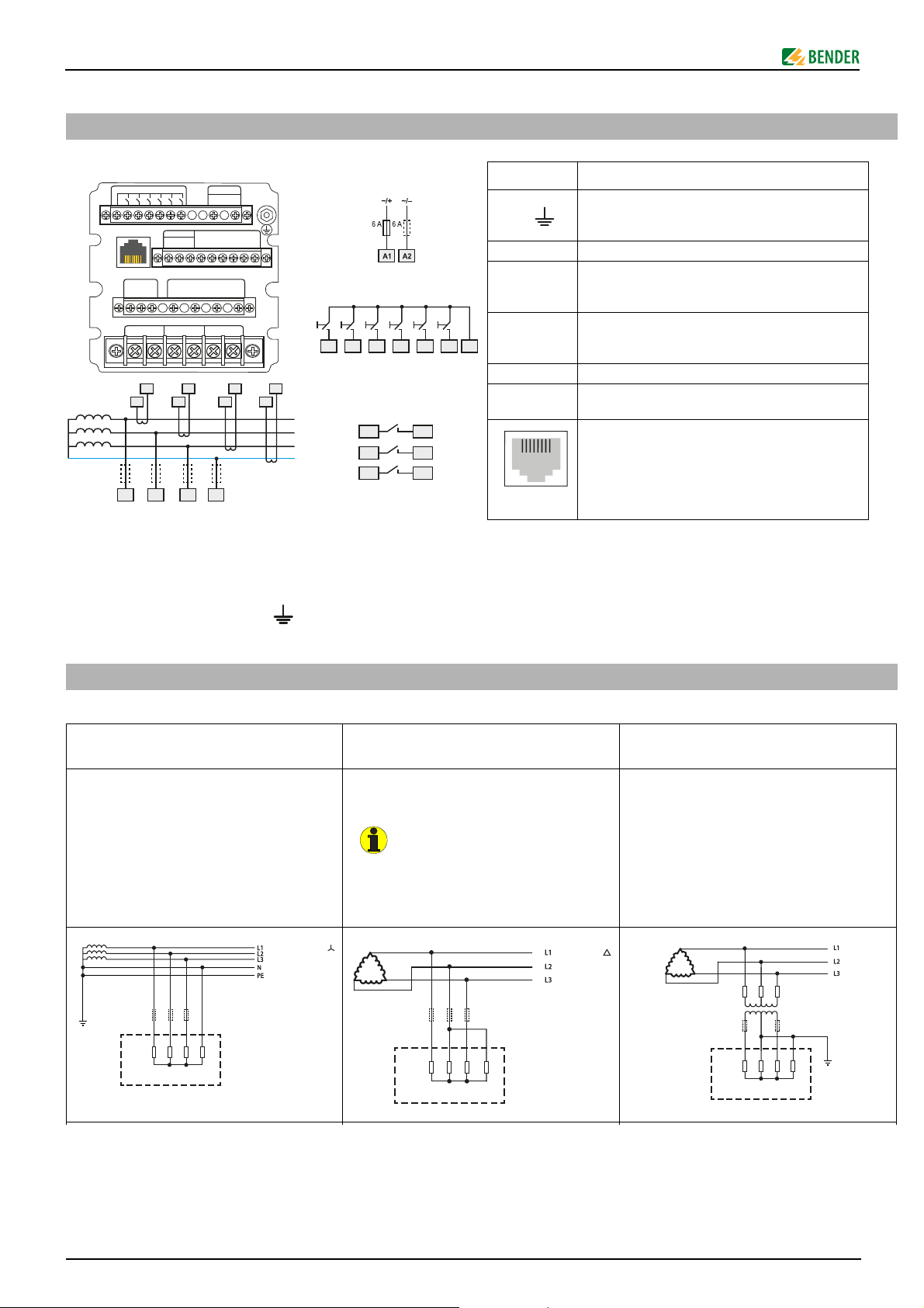
Terminal Description
A1, A2,
Connection to supply voltage, 6 A fuse (when supplied by IT systems, both phase conductors have to
be protected).
DI1…DI6, DIC Digital inputs
DO13, DO14,
DO23, DO24
DO33, DO34
Digital outputs (N/O contacts)
I11, I12,
I21, I22,
I31, I32
Connection to the system to be monitored
D+, D-, SH Connection RS-485 bus
L1, L2, L3, N
Measuring voltage inputs: The measuring leads
should be protected with appropriate fuses.
Modbus TCP: Pin assignment
1 Transmit Data +
2 Transmit Data –
3 Receive Data +
4, 5, 7, 8 not used
6 Receive Data –
Three-phase 4-wire system (TN, TT, IT
systems)
Three-phase 3-wire system Connection via voltage transformers
The PEM can be used in three-phase 4-wire
systems, independent of the type of distribution system (TN, TT, IT system).
The PEM can be used in three-phase 3-wire
systems. The line conductor voltage must not
exceed AC 400 V.
When used in 3-wire systems, the connection type (TYPE) has to be set to delta connection (DELTA).
For this purpose, the measuring inputs L2 and
N are to be bridged.
The coupling via measuring current transformers allows the use of the measuring device in medium and high voltage systems.
The transformation ratio can be adjusted in
the PEM555 (1…2200).
V
Connection of the device
Wiring diagram
DIC DI1 DI2 DI3 DI4 DI5 DI6
RS-485ETH
D+
• l41
l42SH
• l11
l12
• l21 • l31
I12
I11
L1 L2 L3 N
Power
A1 A2
DO34 DO33 DO24 DO23 DO14 DO13
D
-
SH
L1 L2 L3 N
l22 l32
I22
I21
I31
U
S
DI1 DICDI5 DI6DI2 DI3 DI4
I32
I42
I41
L1
L2
L3
N
DO13 DO14
DO23 DO24
DO33 DO34
Connection
1. Connect the device according the wiring diagram. The connections are located on the rear of the device. Connect the
PEM555 to the supply voltage (terminals A1 and A2
resp. +/-). Connect terminal " " to the protective conductor.
Connection diagram voltage inputs
12345678
2. Line protection: 6 A fuse recommended. If being supplied
from an IT system, both lines have to be protected by a fuse.
3. Connection to the RS-485 bus is made via the terminals D+,
D- and SH. Up to 32 devices can be connected to the bus.
The maximum cable length for the bus connection of all
devices is 1200 m.
2
L1L2L3
R
i
PEM
N
AC 400 V / 230 V
PEM
L1L2L3
R
i
N
AC 400 V
L1L2L3
R
i
PEM
PEM555_D00016_00_Q_XXEN/04.2014
N
LV / MV / H
 Loading...