

Page 1
T M
This document is intended as a reference guide to installing and setting a BENDER LIM2010 Line Isolation Monitor. This document includes installation instructions and typical front plate display indications of the device. For complete details, including installation, setup, settings, and troubleshooting,
refer to the LIM2010 user manual.
Only qualied maintenance personnel shall operate or service this equipment. These instructions
should not be viewed as sucient for those who are not otherwise qualied to operate or service this
equipment. This document is intended to provide accurate information only. No responsibility is assumed by BENDER for any consequences arising from use of this document.
LIM2010
Installation Bulletin / Reference Guide
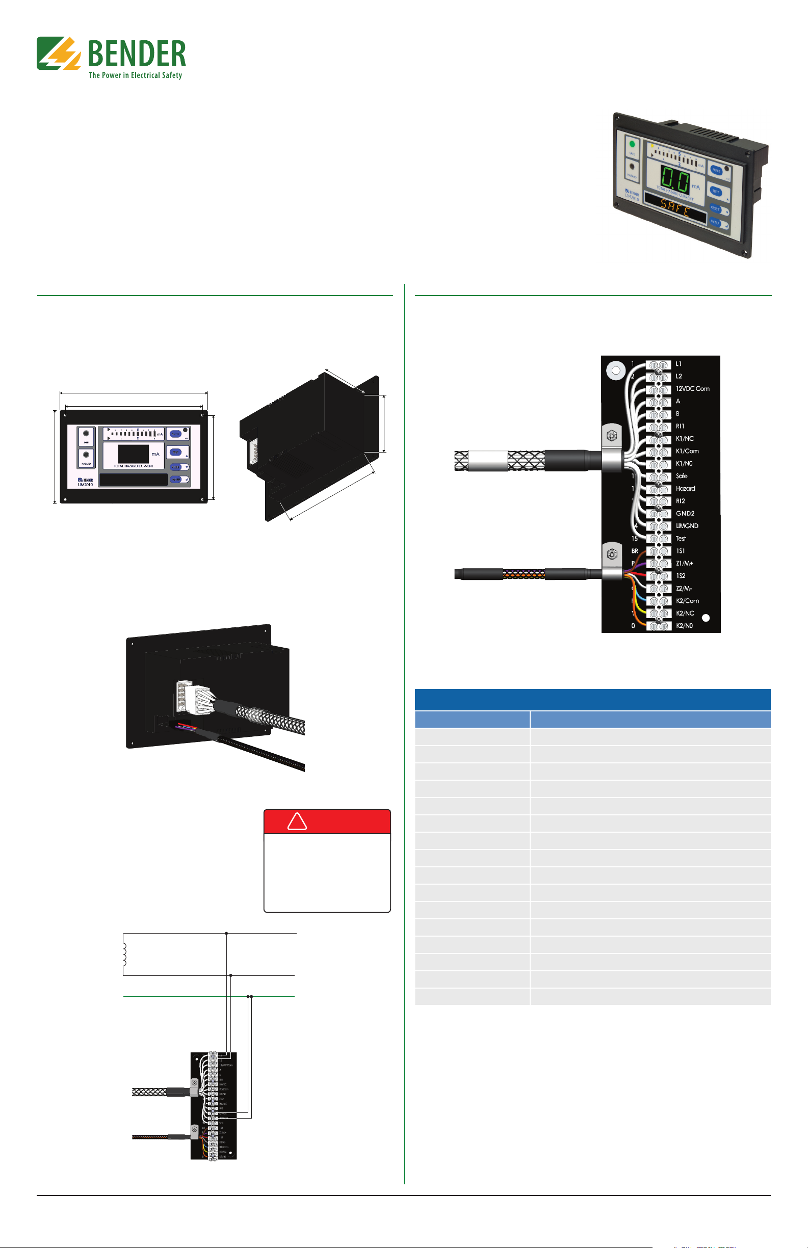
Installation
Mounting
The front plate provides four holes with a diameter of 1/8” (3.2 mm) for screw mounting. Use
the four (4) provided screws for mounting. Use minimum 2.6 lb-in (0.3 N-m), maximum 3.5 lbin (0.4 N-m) torque. Before mounting, plug the connector plate into the LIM. Refer to Figures 1
and 2 for dimensions, listed in inches (mm).
2.4” (62)
7” (177)
6.5” (164)
3.1” (79.5)
4” (101.5)
4.4” (112)
5.3” (134.5)
Figure 1 - LIM2010 dimensions, front view Figure 2 - LIM2010 dimensions, rear isometric view
Wiring
The LIM2010 connects to a connector plate assembly. Use the proper wiring diagram to connect to the assembly. Before mounting the LIM, plug the connector plate into the LIM.
Connector Plate
Actual cable length for connector cables is 20” (50.8 cm). Both plugs are connected to
LIM2010. Connector plate must only be installed in a grounded, metallic enclosure.
Figure 3 - Connecting connector plate plugs to LIM2010
Figure 4 shows wiring the connector plate for basic installation with no accessories. If other equipment is to
be installed, such as remote indicators, fault location, or
load monitoring, or for more information on the connector plate and installation, refer to the LIM2010 user
manual.
Connector plate L1 and L2 connect to the main lines
of the system, on the secondary of the isolation transformer. Connector plate LIMGND and GND2 are sepa-
rate connections to the system ground.
DANGER
!
HAZARD OF ELECTRIC SHOCK,
EXPLOSION, OR ARC FLASH
• Disconnect all power before servicing.
• Reference NFPA 99 / CSA Z32 for
Installation Standard.
L1
Figure 5 - CP-LIM2010 connector plate
Connector plate terminals
Type Description
L1, L2 Connected to secondary of isolation transformer
12 VDC Com. Common connection for remote indicators
A, B RS-485 communication interface
RI1 Test button source for remote indicators
K1/NC Alarm relay K1, N/C
K1/Common Alarm relay K1, common
K1/NO Alarm relay K1, N/O
SAFE "SAFE" light connection for remote indicators
HAZARD "HAZARD" light connection for remote indicators
RI2 Local and system muting from LIM and remote indicators
GND2, LIM GND Separate ground connections
TEST Connection for remote test
Z1/M+, Z2/M- Connection for overtemperature sensor or analog meter
L2
GND
Figure 4 - LIM2010 connector plate wiring - basic installation with no accessories
K2/Common Alarm relay K2, common
K2/NC Alarm relay K2, N/C
K2/NO Alarm relay K2, N/O
Document NAE2028421 • 07.2016 • © Bender Inc. • Page 1/1 • Side 1/2Bender Inc. • USA: 800.356.4266 / 610.383.9200 / medical@bender.org • Canada: 800.243.2438 / 905.602.9990 / info@bender-ca.com • www.bender.org
Page 2
LIM2010
T M
Installation Bulletin / Reference Guide
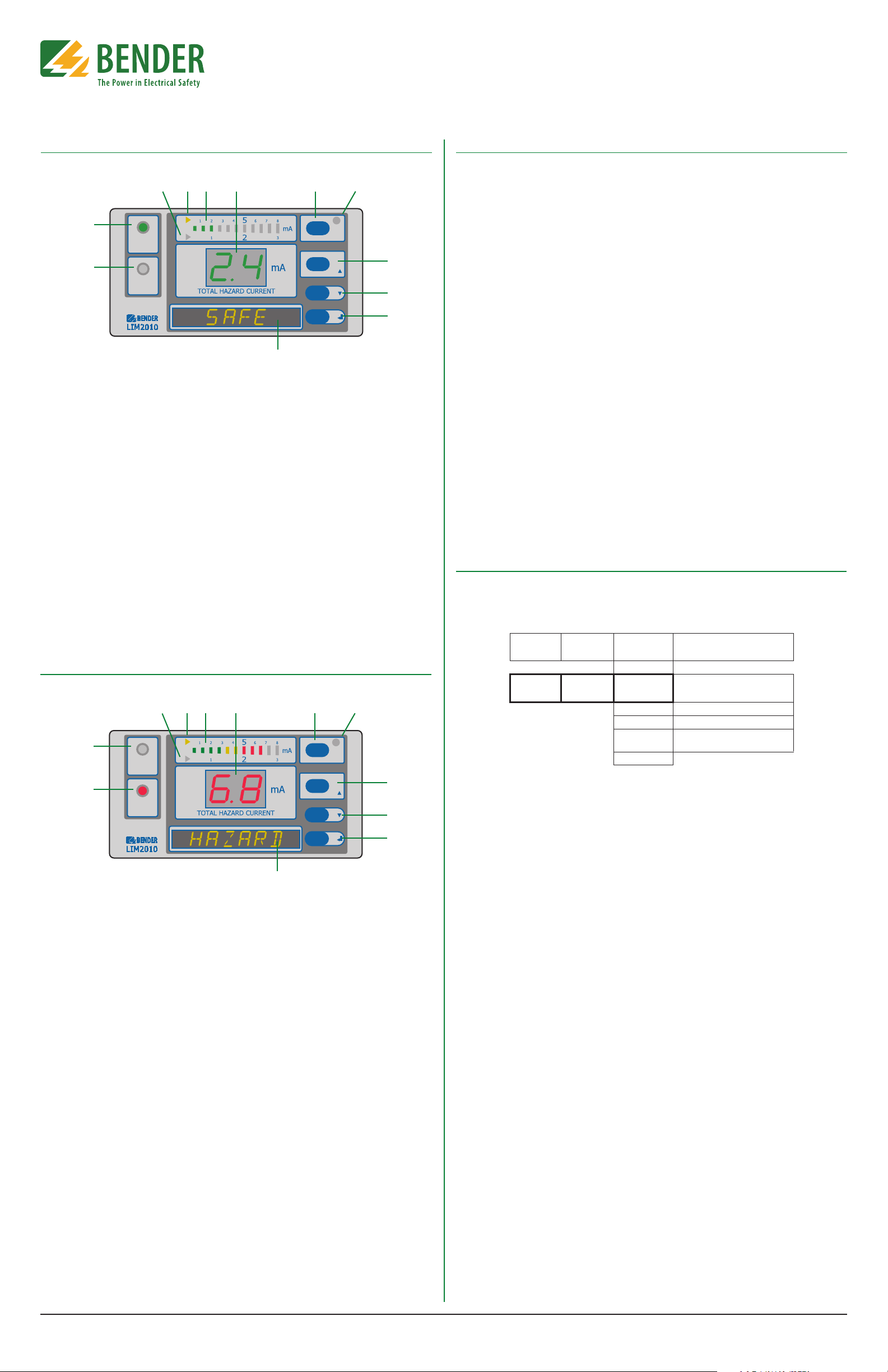
Front Panel Display - Normal Condition
3 4 5 6 7 8
2
SAFE
1
HAZARD
Figure 4 - LIM2010 in the normal condition
1. HAZARD LED (red): Not illuminated.
2. SAFE LED (green): Illuminated. Will be in
the normal condition when the displayed Total Hazard Current is below
the set response value (2 mA or 5 mA).
3. Trip value indication light (yellow):
Indicates that the 2 mA trip level has
been activated.
4. Trip value indication light (yellow):
Indicates that the 5 mA trip level has
been activated.
5. LED bar graph: In a normal condition,
only the green bars are illuminated.
6. Seven-segment display of Total Hazard
Current: Green in color for the normal
condition.
7. MUTE button / ESC key: To go to a high-
8. MUTE LED: Not illuminated in the nor-
9. TEST button: Activates self-test. / UP
10. DOWN key: Moves down in the menu
11. MENU key: Enters the main menu. /
12. Digital display: Reads SAFE in the nor-
MUTE
ESC
TEST
RESET
MENU
9
10
11
12
er level in the built-in menu.
mal condition.
key: To move up in the menu and to increase values.
and to decrease values.
ENTER key: To confirm entries.
mal condition. Also displays menu options when in the device‘s menu.
Navigating the Main Menu
Accessing the main menu
Hold the “MENU” button for at least one second. The device will enter into menu mode. The rst
item in the menu, “VALUES,” will appear. The number “1” will ash.
Entering the password prior to menu navigation
Many submenu options may be password protected. Passwords are entered as three digit
numbers. The default password is 807. When applicable, follow the below procedure to enter
the password:
1. A ashing number illustrates which number is currently in focus.
2. Use the UP/DOWN arrow key to select the correct number.
3. Conrm with the ENTER button.
4. Repeat for the next numbers until the last number is conrmed.
5. Settings may now be modied until the menu is exited. Reentering the menu will require
a reentry of the password.
When a parameter is changed and conrmed with the enter key, the change will have an immediate eect. The LIM2010 will continue to operate while settings are modied.
Exiting the menu
Press the ESC key to return to the last step in the menu. Repeat this step until the display has
returned to the main screen. If the LIM2010 is idle in the menu for 5 minutes, the device will
automatically return to the main screen.
Menu structure
Refer to the LIM2010 user manual for a complete diagram of the LIM2010 menu.
Initializing The Clock (Message Code 8.80)
The LIM2010 utilizes date/time stamping. When initially energized, use the menu diagram below to set the date and time. If message code 8.80 appears on the LIM2010, setting the time
and date will clear this alarm automatically.
Front Panel Display - Alarm Condition
3 4 5 6 7 8
2
SAFE
1
HAZARD
Figure 5 - LIM2010 in the alarm condition
1. HAZARD LED (red): Flashes red.
2. SAFE LED (green): Not illuminated.
3. Trip value indication light (yellow):
Indicates that the 2 mA trip level has
been activated.
4. Trip value indication light (yellow):
Indicates that the 5 mA trip level has
been activated.
5. LED bar graph: In the alarm condition,
the red bars will be illuminated.
6. Seven-segment display of Total Hazard
Current: Red in color for the alarm condition.
7. MUTE button / ESC key: To go to a higher level in the built-in menu.
MUTE
ESC
TEST
RESET
MENU
9
10
11
12
8. MUTE LED: When in the alarm condition, will be illuminated yellow after the
MUTE button has been pressed.
9. TEST button: Activates self-test. / UP
key: To move up in the menu and to increase values.
10. DOWN key: Moves down in the menu
and to decrease values.
11. MENU key: Enters the main menu. /
ENTER key: To confirm entries.
12. Digital display: Reads HAZARD in the
alarm condition.
MENU
Level 1
4. SETTING 7. Clock Tm
MENU
Level 2
EXIT
Dy 12/23 Date: month/day
Yr 2011 Year
DST auto
EXIT
Figure 6 - Menu structure for changing date and time
MENU
Level 3
10.34
A
Meaning
Time: am/pm
Daylight saving time: auto/o
(North America time zones only)
Document NAE2028421 • 07.2016 • © Bender Inc. • Page 1/1 • Side 2/2Bender Inc. • USA: 800.356.4266 / 610.383.9200 / medical@bender.org • Canada: 800.243.2438 / 905.602.9990 / info@bender-ca.com • www.bender.org
 Loading...