

Bender LIM2000plus LIM2000-1, LIM2000plus LIM2000-1CB, LIM2000plus LIM2000-3CB Operating Manual
Page 1
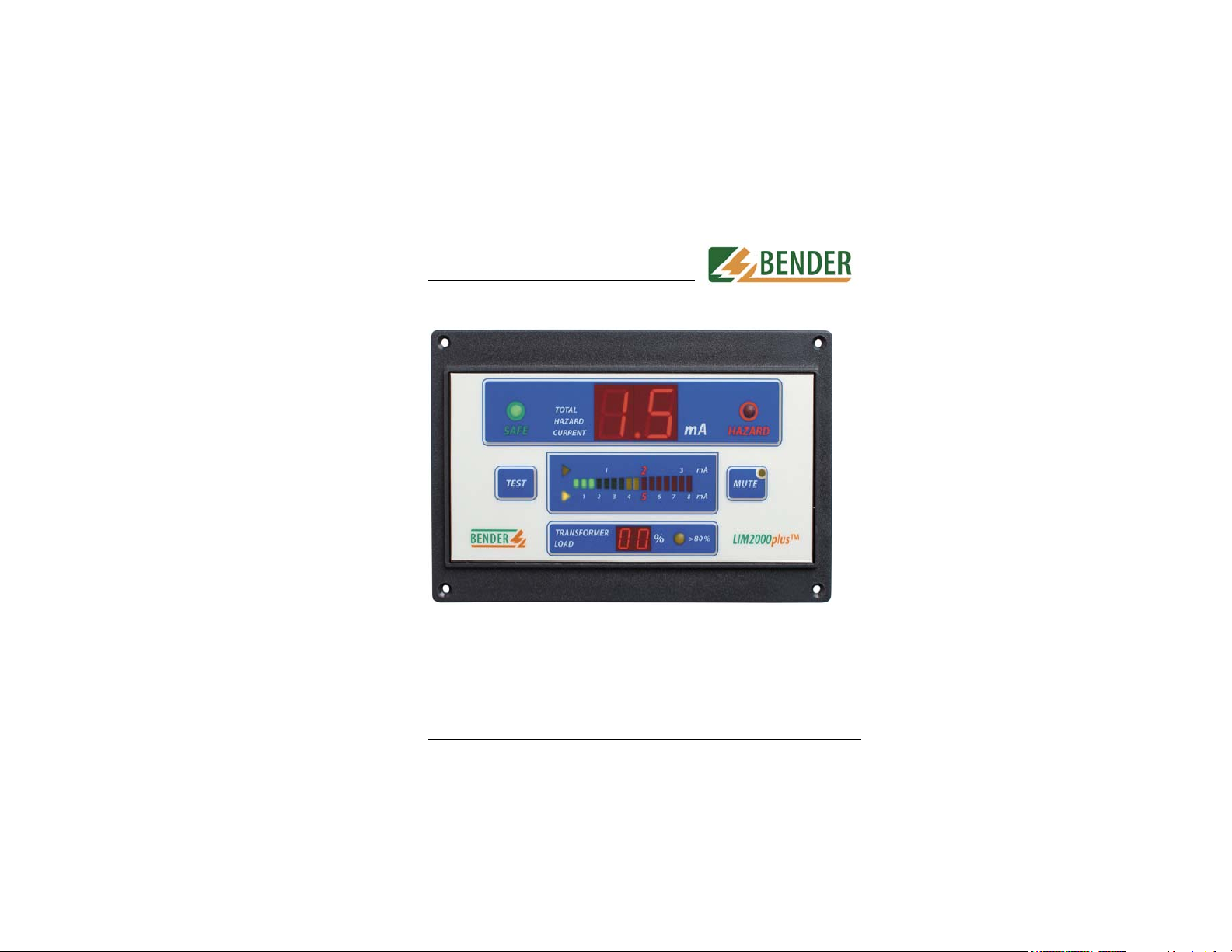
Operating Manual LIM2000plus™
Line Isolation Monitor LIM2000-1
LIM2000-1CB
LIM2000-3CB
TGH 1337 Edition 01/06
Page 2

Table of Contents
Operating manual ...................................
1. Safety Information ............................................... 5
1.1 Intended use ....................................................... 5
1.2 Warranty and liability ........................................... 5
1.3 Personnel ............................................................ 6
1.4 About the operating manual ................................ 6
1.5 Hazards when handling the Line Isolation Monitor
LIM2000-1, LIM2000-1CB and LIM2000-3CB ..... 6
1.6 Inspection, transport and storage ........................ 7
1.7 Important ............................................................. 7
1.8 Explanation of symbols and notes ...................... 8
1.9 Directives for installation ..................................... 9
2. General Information .......................................... 11
2.1 The fundamental functions ................................ 11
2.2 Display .............................................................. 12
2.3 Menu ................................................................. 13
2.4 Error Code Listing ............................................. 15
2.5 External Connections ........................................ 16
ISOTROL / BENDER Medical Products
700 Fox Chase
Coatesville, PA 19320
Telephone: 1-610-383-9200
Fax: 1-610-383-7100
Tollfree: 1-800-833-6834
Rights to modification reserved
2
2.5.1 Cable Assembly (CP-LIM2000).......................... 17
2.5.2 Cable Assembly (CP-LIM2000CB) .................... 18
2.6 Accessories ....................................................... 19
2.6.1 Remote Indicator ............................................... 19
2.6.2 Digital Remote Indicator .................................... 20
3. Technical Description ........................................ 21
3.1 Technical Data .................................................. 22
4. Information Request .......................................... 23
3
Page 3
1. Safety Information
1.1 Intended use
The Line Isolation Monitor (LIM) calculates the total hazard
current in a single phase or three phase isolated power
system. This is the maximum current that could flow through
a person who made contact between an isolated conductor
and ground.
Two seperate ground connections are provided for added safety
when wiring the LIM into an isolated power system. Each ground
should be wired individually to the reference grounding bus. A break
in either connection will cause the LIM to alarm (flashing red LED).
Any other use, or any use beyond the foregoing, is deemed to be
improper. The BENDER companies shall not be liable for any loss
and damaging arising therefrom.
Correct use also includes
• compliance with all instructions from the operating manual
• adherence to any inspection intervals.
As a basic principle, our “General conditions of Sale and Delivery“
shall apply. These are available to the operator not later than the
time when the contract is concluded.
1.2 Warranty and liability
Warranty and liability claims in the event of injury to persons or
damage to property are excluded if they can be attributed to one or
more of the following causes:
• Improper use of the LIM.
• Improper assembly/fitting, commissioning, operation and
maintenance of the LIM.
• Failure to take note of the operating instructions concerning
transportation, commissioning, operation and maintenance of
the LIM.
• Unauthorized structural modifications to the LIM.
• Failure to take note of the technical data.
4
5
Page 4
. Safety Information
r
1. Safety Information
• Improperly performed repairs and the use of spare parts o
accessories which are not recommended by the
manufacturer.
• Cases of disaster brought about by the effect of foreign
bodies and force majeure.
• The assembly and installation of non-recommended
combinations of devices.
This operating manual, and in particular the safety information,
must be noted by all persons who work with the LIM. In addition,
it is essential to comply with the rules and regulations on
accident prevention which are valid for the place of use.
1.3 Personnel
Only appropriately qualified personnel may work on the LIM.
“Qualified“ means that such personnel are familiar with the
installation, commissioning and operation of the LIM, and that
they have undergone training or instructions which is appropriate
to the activity. The personnel must have read and understood
the safety chapter and the warning information in these operating
instructions.
1.4 About the operating manual
This operating manual has been compiled with the greatest
possible care. Nevertheless, errors and mistakes cannot be
entirely ruled out. BENDER companies assume no liability
whatsoever for any injury to persons or damage to property
which may be sustained as a result of faults or errors in these
operating
instructions.
1.5 Hazards when handling the Line Isolation Monitor
LIM2000-1, LIM2000-1CB and LIM2000-3CB
The LIM is constructed according to state of the art and the
recognised safety engineering rules. Nevertheless, when it is
6
being used, hazards may occur to the life and limb of the user or of
third parties, or there may be adverse effects on the LIM or on other
valuable property. The LIM must only be used
• for the purpose for which it is intended
• when it is in perfect technical condition as far as safety is
concerned
Any faults which may impair safety must be eliminated immediately.
Impermissible modifications and the use of spare parts and
additional devices which are not sold or recommended by the
manufacturer of the LIM may cause fire, electric shocks and
injuries.
Unauthorized persons must not have access to or contact
with the LIM.
Warning signs must always be easily legible. Damaged or illegible
signs must be replaced immediately.
1.6 Inspection, transportation and storage
Inspect the dispatch packaging and the equipment packaging for
damage, and compare the contents of the package with the delivery
documents. In the event of damage during transportation, please
notify the BENDER company immediately.
The LIM must only be stored in rooms where they are protected
against dust and moisture, and spraying or dripping water, and
where the indicated storage temperatures are maintained.
1.7 Important
Please check for correct system and supply voltage !
When insulation and voltage tests are to be carried out, the device
must be isolated from the system for the test period.
In order to check the proper connection of the LIM, it is
recommended to carry out a functional test, before starting the LIM.
Please check whether the basic setting of the devices complies with
the system requirements.
Children or the public must not have access to the LIM.
7
Page 5

1. Safety Information
1. Safety Information
.8
The following designations and symbols for hazards and
warnings are used in BENDER documentation.
This symbol means a possible threat of danger to the
life and health of human beings.
• Failure to comply with these warnings means that
death, serious physical injury or substantial damage
to property may ensue if the relevant precautions
are not taken.
This symbol means a possible dangerous situation.
• Failure to comply with these warnings means that
slight physical injury or damage to property may
ensue if the relevant precautions are not taken.
This symbol gives important information about the
correct handling of the LIM.
• Failure to comply with this information can result in
faults on the LIM or in its environment.
1.8 Directions of installation
Where you see this symbol, you will find application
hints and other particularly useful information.
• This information will help you to make an optimal
use of the LIM.
8
9
Page 6

10
2. General Information
2.1 The fundamental functions
The LIM function is to calculate the max. value of the total hazard
current that would flow through a solid connection between the
isolated current carrying conductor associated with the higher
impedance and ground. The total hazard current is displayed
on a 7-segment LED display and an analog bargraph with 16
LEDs. The level will increase as additional loads are connected
to the system or when a ground fault is slowly developing or has
occured.
The bargraph has two scales, one for 2mA and one for 5 mA alarm
setting. The two yellow LEDs on the left near the bargraph
indicate, which alarm setting is selected and which scale is valid.
There is a visual and audible alarm when the total hazard current
exceeds the setting of either 2 or 5mA. The visual alarm remains
during duration of the fault, the buzzer can be muted at any time.
When muted, the yellow LED inside the mute button comes on to
indicate a muted condition.
Activating the test button starts the following procedures:
- Audible alarm check
- Illumination of the analog LED bargraph
- Illumination of the 7-segment LED displays of the total hazard
current and the optional transformer load
- Internal hardware check and self calibration by using internal
faults (the numeric Display of the optional transformer load
indicates CH or CL depend on 120 or 240V).
If these tests are successful, the LIM goes in the operating
condition, otherwise the LIM displays an errorcode. After the fault
of the error has abolished it works again in the operating condition,
when the internal tests are finished.
The LIM also performs an internal hardware check and a
self-calibration after 3 hour and then every 12 hours. If this checks
aren´t successful the LIM displayes an error-code too.
The LIM has provisions for connecting one or two remote
indicators with or without meter or digital display. Relay output
contacts are also available which can be wired into a circuit to
trigger an external alarm.
11
Page 7

y
2. General Information
2. General Information
2.2
ispla
1. Amber THC setting LEDs - indicates the current “THC” setting
2. “TEST” button - checks functions of the LIM
3. Green “SAFE” LED - bright unless LIM is in alarm mode
4. LED Analog Bar Graph - displays Total Hazard Current
5. Total Hazard Current Red LED Display - displays Total Hazard
Current
6. Red “Hazard” LED - indicates “THC” >
7. Amber “MUTE” LED button silences alarm buzzer
8. Amber “Transformer Load” LED indicates transformer load over 80%
(optional)
9. Tranformer Load (TL) Red LED Display - displays transformer load
(optional)
5mA (2mA)
2.3 Menu
To enter the menue the TEST button and the MUTE button must
be pushed simultaneously for approximately 1 second till the
buzzer begins to beep. The numeric display indicates set Point
(SP).
Now the TEST button has the function to swap upwards in the
menu.The MUTE button has the function to confirm or to activate
the selected parameters.
In the menu the following functions can be selected:
• Sound intensity of buzzer (hi or lo)
• Max. transformer load (100% of the transformer current)
After setting the parameters, they are stored and after leaving the
menu the LIM performs a new self test.
12
13
Page 8

TEST
Buzzer volume
Sets the intensity of
the buzzer volume
loud
quiet
2. General Information
Start menu
(push TEST and MUTE button
simultaneously)
TEST
Buzzer volume
Max. transformer current (optional)
Quit menu and activate parameters
MUTE
Response value of the
load monitoring. Adjustments
in 5% steps between 10%
and 100% of used CT.
, ... , (100),
(off).
MUTE
TEST
quit menu and
store new parameters
2. General Information
2.4 Error-Codes Listing
ER 1.0 Ground error LIM-GNDor GND interrupted
ER 2.0 AD converter calibration failed; hardware failed
error
ER 3.0 Measuring circuit test failed; hardware mistake
ER 4.0 Tolerance between actual system voltage and
calibrated system voltage has been increased
ER 4.5 Tolerance between actual signal voltage and
calibrated system voltage has been increased
ER 5.0 Hardware defect; missing system trigger
ER 6.0 Program sequence interrupted; EMI interference
ER 6.5 Program sequence interrupted; stack point
indication too high
ER Error in the current measuring circuitry
14
MUTE
MUTE
MUTE
menu
END
15
Page 9

2. General Information
2. General Information
2.5.1 Connector assembly
(CP-LIM2000)
Connections between the LIM, the Remote Indicator and the
isolated power supply are made via this cable assembly,
designed for integration into panels, headwalls and other
equipment.
The terminal strip works best with 18 ga. wire.
The multiconductor harness has a length of 20”.
16
17
Page 10

2
(CP-LIM2000CB)
Connections between the LIM, the Remote Indicator, the load
monitoring CT and the RS485-Interface are made via this cable
assembly, designed for integration into panels, headwalls and
other equipment.
The terminal strip works best with 18 ga. wire.
The multiconductor harness has a length of 20”.
2. General Information2. General Information
2.5.1 Remote Indicator
The MK2000 Remote Indicator series permanently mounts into
standard one- to xxx-gang electrical boxes. Low voltage wiring
connects them via the connector assembly CP-LIM2000 to the
Line Isolation Monitor.
The remotes can duplicate the audible and visible “SAFE”,
“HAZARD” and “OVERLOAD” (optional) signals of the LIM.
A “MUTE” button can either silence the remote buzzer (local
muting) or all buzzers in the system (system muting). The
optional “TEST” button can remotly perform a function test of the
LIM.
18
19
Page 11

2. General Information
3. Technical Description
The MK2000CB Digital Remote Indicator permanently mounts
into standard two- to xxx-gang electrical box. Low voltage wiring
connects it via the connector assembly CP-LIM2000 to the Line
Isolation Monitor.
The remote can duplicate the audible and visible “SAFE”,
“HAZARD” and “OVERLOAD” (optional) signals of the LIM.
A “MUTE” button can either silence the remote buzzer (local
muting) or all buzzers in the system (system muting). The
optional “TEST” button can remotly perform a function test of the
LIM.
Additional to that there are two 7-segment-displays indicating the
Total Hazard Current and the Transformer Load current.
The Line Isolation Monitor is based on the superimposition of
a measuring signal on the isolated power system. The signal is
very small and near the frequency of the power line making it
compatible with all electrical equipment due to ist low EMI. This
signal is connected between each of the lines and ground and
flows through the system leakage impedances producing an
interference (beat frequency) pattern. The difference frequency
produces an envelope directly proportional to the system
leakage. This is extracted from the power line and processed.
The resulting measurement is a very accurate determination of
the total leakage current on the isolated power system.
The BENDER LIM (US Patend #4,472,676) meets or exceeds all
applicable U.S. and Canadian standards.
It complies with NEC Article 517, NFPA 99, UL 1022, and is
recognized under UL and CUL File No.E224808 (Listee:
BENDER Inc.).
20
21
Page 12

3. Technical Description
Rated insulation voltage 300 V
Insulation class in acc. to UL1022
Dielectric voltage-withstand test 1500 V
Rated service rating continuous operating
Rated mains voltage of VN see nameplate
Frequency range of VN 50…60 Hz (+/- 5%)
Operating range of VN 85…110% of rated voltage
Max. power consumption 22 VA
Measuring current max. 20 µA
Monitor hazard current 120V / 208V (1Ph) / 208V (3Ph) max. 35 /
62 / 68 µA
Min. internal impedance at 1Ph / 3Ph (60 Hz) 3.5 / 3.2 MΩ
Nominal response value 2 mA changeable to 5 mA
Response tolerance 1.8…2 mA or 4.5…5 mA
Response retardation < 4 sec.
Response hysteresis 20% of response value
Output contact assemblies one voltage-free SPDT and one 12 V
DC, 200mA contact
Rated contact voltage 250 V AC / 24VDC
Make capacity 4A AC / 4A DC
Break capacity at 24 V DC and L/R = 0 4 A
Switching life (220 V AC / 60 Hz) 2 x 10
Operation mode continuous
LIM overload protection built-in thermal overload with automatic
reset
º
Ambient temperature when operating 10
Ambient temperature when stored -20
C…50ºC, 50ºF…122ºF
º
C…50ºC, 10ºF…122ºF
Mounting orientation any
Connector 15 pin Molex, type 03-09-2152
Weight approx. 1.1 lb (493gr.)
5
cycle
Information Request
Information Request
Questions or Comments? Just call!
Tollfree: 1-800 833-6834
Customer Service, Sales andTechnical Support:
1-610-383-9200
Fax: 1-610-383-7100
For further information please write down:
Model:...............................................
Article No.:......................................
Serial No.:.........................................
Voltage:...........................................
Date Purchased:................................
Notes:
Thank you for purchasing a BENDER Line Isolation Monitor.
We appreciate your business.
22
23
 Loading...