

Bender LifeGuard Reference Manual

LifeGuard® Series (Digital)
T M
This document is intended as a reference guide for installing and using a BENDER LifeGuard series
Ground Fault Circuit Interrupter (GFCI) with digital display option. This document includes installation, setup, and usage instructions. For complete instructions, including setup, use, and troubleshooting, refer to LifeGuard user manual, document NAE1085011.
Only qualied maintenance personnel shall operate or service this equipment. These instructions
should not be viewed as sucient for those who are not otherwise qualied to operate or service this
equipment. This document is intended to provide accurate information only. No responsibility is assumed by BENDER for any consequences arising from use of this document.
Installation Bulletin / Reference Guide
Use of This Document
This installation guide applies to the special digital display version (option “D”) of the LifeGuard
GFCI which meets the following requirements:
• Uses door mounted MK1500-D remote (backplate only models have connections)
• Uses “6” or “20” option (6 mA xed or 20 mA xed trip level)
For compact LifeGuard GFCI models, consult document NAE1088320. For standard LifeGuard
GFCIs with pushbutton front, consult document NAE1088011. For all models, consult the full
LifeGuard GFCI user manual, document NAE1085011.
Installation
Mounting - NEMA 4X Polycarbonate Enclosure
The standard enclosure for LifeGuard series GFCIs is a NEMA 4X polycarbonate enclosure. The
enclosure includes mounting feet and separate instructions on wall-mounting the enclosure.
Refer to these instructions for more infromation. Refer to gure 1 below for dimensions.
Figure W1 - Single-Phase, Two-Wire Configurations (L1, N)
Figure W2 - Three-Phase, Three-Wire Configurations (L1, L2, L3)
Figure 1 - Dimensions of NEMA 4X polycarbonate enclosure
Table 1: Enclosure Dimensions in Inches (mm)
Type Enclosure A x B C D E F G
< 100 A 12x10x6
100 A 14x12x6
For other enclosure types, refer to LifeGuard user manual, document NAE1085011.
If the LifeGuard GFCI was purchased without an enclosure (backplate only), consult the following section “Wiring,” as well as the section “Backplate Only Models” on the reverse side of this
document for additional mounting and wiring requirements.
10.25“ x 8.25“
(260.5 x 209.5)
12.25“ x 10.25“
(311 x 260.5)
12.75“
(324)
14.75“
(375)
10.75“
(273)
12.75“
(324)
13.4“
(340)
15.4“
(391)
7.7“
(195.5)
7.7“
(195.5)
12.3“
(312.5)
14.3“
(363)
Wiring
The GFCI is installed in series with the main circuit. Connection of the main circuit conductors
varies based on quantity of conductors and system voltage. In general, the following steps
must be taken:
• All active conductors, including the neutral, must be
brought into the device, through the current transformer, and landed on the line side of the contactor.
• All active conductors are then brought out from the
load side of the contactor to the load / remaining
branch of the circuit.
• The ground wire is landed on the ground lug on the
backplate. The ground wire is NOT routed through
the current transformer.
HAZARD OF ELECTRIC SHOCK,
EXPLOSION, OR ARC FLASH
• Disconnect all power before servicing.
• Observe all local, state, and national
codes, standards, and regulations.
DANGER
!
Figure W3 - Three-Phase, Four-Wire Configurations (L1, L2, L3, N)
Figure W4 - 240Y/120 VAC Configurations (L1, L2, N)
Table 2: Legend of Wiring Diagrams
Voltage
120 VAC 1ph / 2w (L1, N) Figure W1
208 VAC 3ph / 3w (L1, L2, L3) FIgure W2
208/120 VAC 3ph / 4w (L1, L2, L3, N) Figure W3
240/120 VAC 3ph / 3w (L1, L2, N) Figure W4
277 VAC 1ph / 2w (L1, N) Figure W1
480 VAC 3ph / 3w (L1, L2, L3) Figure W2
480/277 VAC 3ph / 4w (L1, L2, L3, N) Figure W3
600 VAC 3ph / 3w (L1, L2, L3) Figure W2
600/346 VAC 3ph / 4w (L1, L2, L3, N) Figure W3
Conductors (NOT including
ground)
Referenced Wiring Diagram
Document NAE1088440 • 02.2013 • © Bender Inc. • Page 1/1 • Side 1/2Bender Inc. • USA: 800.356.4266 / 610.383.9200 / info@bender.org • Canada: 800.243.2438 / 905.602.9990 / info@bender-ca.com • www.bender.org
T M
This section only applies to LifeGuard models purchased without an enclosure and on the
backplate only. Refer to instructions below for additional requirements for installation and
wiring. Backplate-only models are typically integrated into existing cabinets or machinery.
Mounting - Backplate Only
Refer to Figure 3 below for dimensions. The GFCI must be mounted in a location sucient to
protect live electrical equipment. Use four (4) #10 screws for mounting. The vertical clearance
of the backplate is 6” for models less than 100 A, and 8” for 100 A models.
A
C
Backplate Dimensions in Inches (mm)
Type A x B C x D
LifeGuard® Series (Digital)
Installation Bulletin / Reference Guide
Use - Enclosure FrontAdditional Requirements - Backplate Only Models
1
2
3
MK1500
POWER
ON
5
5
0
.
.
I mAI mA
25 50 75 100
TEST RESET
GFCI-SERIES
CIRCUIT
TRIPPED
%
4
5
6
Figure 3 - DImensions of LifeGuard, backplate only
D
B
100 A
< 100 A
8.75“ x 10.5“
(222 x 267)
10.75“ x 12.75“
(273 x 324)
8.25“ x 10.25“
(210 x 260)
Wiring - Control and Remote Indicator Wiring
LifeGuard part numbers ending in “-N-D” apply to this section. Follow the standard wiring instructions on the reverse side of this document. Additionally, backplate only models may connect to additional devices for remote capabilities.
Test and reset functions are carried out in one of the following ways:
• Using the test and reset pushbuttons located directly on the ground fault module
• Connecting an MK1500-D remote indicator and using the built-in test and reset buttons
• Connecting an MK1500-D remote indicator and using the TEST, RESET, and T/R terminals to
connect external test and reset pushbuttons
The MK1500-D duplicates indication and test/reset pushbutton functionality. Additionally, terminals are provided for external test and reset. Both are normally open (N/O) contacts.
Observe the following additional requirements:
• Use shielded RS-485 cable, AWG 18 for connections “A” and “B.”
• The red switch labeled “R” on the underside of the ground fault module must be switched
to ON to ensure proper RS-485 termination. Standard RS-485 cable length limitations apply.
• External test and reset control connections are optional and not necessary for the built-in
test and reset functionality of the MK1500-D and ground fault module.
• The MK1500-D requires an external supply voltage not supplied from the backplate, connected to terminals A1 and A2. The supply voltage range is 100-240 VAC, 50/60 Hz.
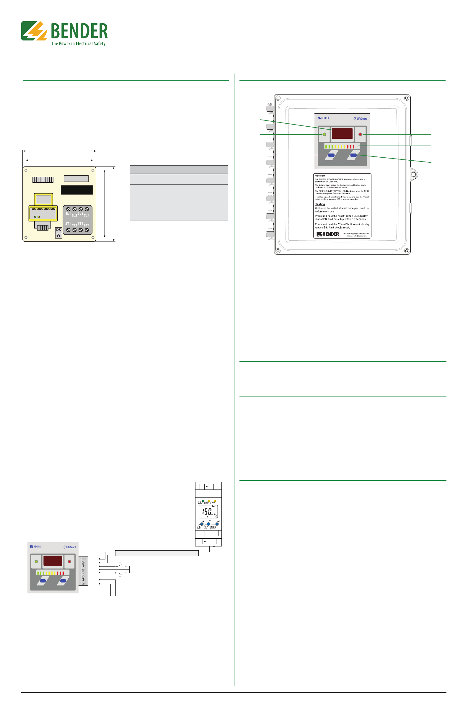
Figure 3 - Front of LifeGuard enclosure with digital indicator
1. Digital display: Shows measured
ground fault current in real-time.
2. POWER LED: Illuminates when the GFCI
has received power and has not
tripped.
3. TEST button: Performs a functional test
of the GFCI (instructions for use below).
4. TRIPPED LED: Illuminates when the
GFCI has tripped.
5. LED bar graph: Indicates how close the
GFCI is to tripping.
6. RESET button: Resets the GFCI if faults
have been cleared (instructions for use
below).
Field Adjustments
LifeGuard GFCIs with digital display utilize ground fault modules which are not eld-adjustable.
Models are either xed at a 6 mA or 20 mA trip level, depending on option.
Operation
Apply power to the GFCI
To apply power, close the circuit breaker / disconnect on the line side of the GFCI. If there are no
ground faults present on the system, the green ON LED will illuminate.
Refer to the wiring diagram below for additional wiring required for the MK1500-D. For additional information on installation and use of the remote indicator, refer to MK1500-D installation manual. Do not modify any other wiring on the backplate when installing the remote
indicator.
RCMA421H-DCB-2
RCMA426H-DCB-2
A1 A2T1
21 22 24
A B
T2
MK1500
POWER
ON
MK1500-D
I mAI mA
25 50 75 100
TEST RESET
GFCI-SERIES
CIRCUIT
TRIPPED
%
A
B
RESET
T/R
TEST
A2
A1
To supply voltage
100-240 VAC
RS-485 cable: twisted, shielded pair
(Optional External
Test/Reset Connections)
Test procedure
• Press and hold the TEST button until display reads “tES.” An internal self-test will initiate.
Unit must trip within 15 seconds. Power to any connected loads will be interrupted.
• Press and hold the RESET button until display reads “rES.” Power will be restored to the load
side of the GFCI.
Error Codes
For error codes and troubleshooting, refer to LifeGuard user manual, document NAE1085011.
For digital display models, error codes will appear both on the internal ground fault module as
well as the display of the door-mounted remote indicator.
Figure 4 - Wiring MK1500-D remote indicator to LifeGuard GFCI on backplate only (no enclosure)
Document NAE1088440 • 02.2013 • © Bender Inc. • Page 1/1 • Side 2/2Bender Inc. • USA: 800.356.4266 / 610.383.9200 / info@bender.org • Canada: 800.243.2438 / 905.602.9990 / info@bender-ca.com • www.bender.org
 Loading...