

Bender ISOMETER isoPV425 with AGH420 User Manual
EN
Manual
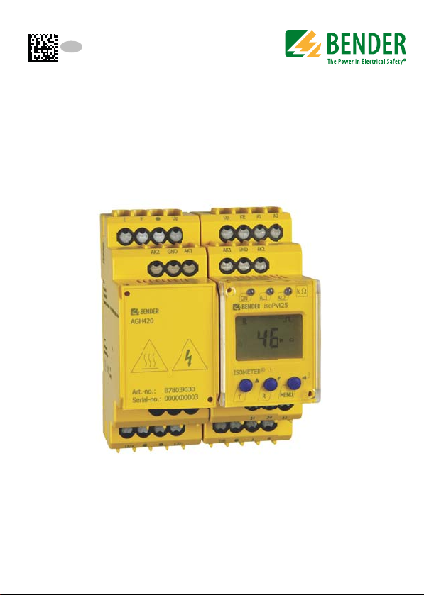
ISOMETER® isoPV425
with AGH420 coupling device
Insulation monitoring device for unearthed
IT AC, AC/DC and DC systems
for photovoltaic systems up to AC 690 V / DC 1000 V
Software version: D404 V1.0x
isoPV425_D00028_02_M_XXEN/09.2014

Bender GmbH & Co. KG
Londorfer Str. 65 • 35305 Gruenberg • Germany
Postfach 1161 • 35301 Gruenberg • Germany
Tel.: +49 6401 807-0
Fax: +49 6401 807-259
E-Mail: info@bender.de
Web: http://www.bender.de
http://www.bender-emobility.com
© Bender GmbH & Co. KG
All rights reserved.
Reprinting only with permission
of the publisher.
Subject to change!

Table of Contents
1. Making effective use of this document ....................................................... 5
1.1 How to use this manual ................................................................................. 5
1.2 Information about factory setting ............................................................. 6
2. Safety instructions ........................................................................................... 7
2.1 General safety instructions ........................................................................... 7
2.2 Work activities on electrical installations ................................................ 7
2.3 High surface temperature due to operational conditions ................ 8
2.4 Intended use ...................................................................................................... 8
3. Function ............................................................................................................. 9
3.1 Device features ................................................................................................. 9
3.2 Description of function ............................................................................... 10
3.2.1 Undervoltage/overvoltage monitoring ................................................ 11
3.2.2 Connection monitoring .............................................................................. 11
3.2.3 Self test, automatic ....................................................................................... 11
3.2.4 Self test, manual ............................................................................................ 12
3.2.5 Malfunction ..................................................................................................... 12
3.2.6 Assigning alarm categories to alarm relays K1/K2 ............................ 12
3.2.7 Time delays t, ton and toff ....................................................................... 12
3.2.8 Password protection (on, OFF) ................................................................. 13
3.2.9 Automatic adaptation of the measuring pulse duration ................ 13
3.2.10 Response time ................................................................................................ 13
3.2.11 Factory setting FAC ...................................................................................... 13
3.2.12 External, combined test resp. reset button T/R ................................. 13
3.2.13 Fault memory ................................................................................................. 14
3.2.14 History memory HiS ...................................................................................... 14
isoPV425_D00028_02_M_XXEN/09.2014
3

Table of Contents
4. Installation, connection and commissioning ........................................... 15
4.1 Installation ....................................................................................................... 15
4.2 Connection ...................................................................................................... 17
4.3 Commissioning .............................................................................................. 20
5. Operation and configuration ...................................................................... 21
5.1 Factory setting ................................................................................................ 21
5.2 Getting to know the user interface ......................................................... 22
5.3 Understand information on the display ................................................ 23
5.3.1 Querying measured values ........................................................................ 24
5.3.2 Alarm display when an insulation fault has been detected .......... 26
5.4 Display in menu mode ................................................................................ 27
5.4.1 Querying and setting parameters: Overview ...................................... 27
5.4.2 Navigation within the menu ..................................................................... 28
5.4.3 Selecting menus ............................................................................................ 31
5.4.4 Making settings in the AL menu .............................................................. 33
5.4.5 Making settings in the out menu ............................................................ 35
5.4.6 Making settings in menu t ......................................................................... 40
5.4.7 Making settings in the SEt menu ............................................................. 42
5.4.8 Querying software number and software version with the INF
menu .................................................................................................................. 45
5.4.9 Querying an erasing the history memory in the HiS menu ........... 45
6. Technical data ................................................................................................ 47
6.1 Technical data isoPV425 ............................................................................. 47
6.2 Technical data AGH420 ............................................................................... 50
6.3 Standards, approvals and certifications ................................................ 52
6.4 Ordering information ................................................................................... 52
6.5 Error codes ....................................................................................................... 53
INDEX .................................................................................................................... 55
4
isoPV425_D00028_02_M_XXEN/09.2014
1. Making effective use of this document
1.1 How to use this manual
This manual is intended for electrically skilled persons working in
electrical engineering and electronics!
To make it easier for you to understand and revisit certain sections of text and
instructions in the manual, we have used symbols to identify important instructions and information. The meaning of these symbols is explained below:
The signal word indicates that there is a high risk of danger
that will result in electrocution or serious injury if not
avoided.
This signal word indicates a medium risk of danger that can
lead to death or serious injury if not avoided.
This signal word indicates a low level risk that can result in
minor or moderate injury or damage to property if not
avoided.
This symbol denotes information intended to assist the user
to make optimum use of the product.
isoPV425_D00028_02_M_XXEN/09.2014
5

Making effective use of this document
1.2 Information about factory setting
Page 21 provides a summary of all factory settings.
If you want to reset the ISOMETER® to its factory setting in a specific case, refer
to page 44.
6
isoPV425_D00028_02_M_XXEN/09.2014
2. Safety instructions
2.1 General safety instructions
In addition to these operating instructions, the "Important safety instructions
for Bender products“, which are also included in the scope of supply, are an
integral part of the device documentation.
2.2 Work activities on electrical installations
Danger as a result of unprofessional work!
Failure to carry out work on electrical installations properly
and correctly can put life and limb at risk! Therefore, observe
the following safety instructions!
Only skilled persons are permitted to carry out the work necessary to
install, commission and run a device or system.
Compliance with the applicable regulations governing work on electri-
cal installations and with the regulations derived and associated with
them, is mandatory. EN50110 is of particular importance in this regard.
If the device is being used in a location outside the Federal Republic of
Germany, the applicable local standards and regulations must be complied with. European standard EN 50110 can be used as a guide.
isoPV425_D00028_02_M_XXEN/09.2014
7

Safety instructions
2.3 High surface temperature due to operational conditions
Danger from touching hot surfaces!
If the AGH420 is operated at system voltages > 800 V, the
temperature of the enclosure may exceed 60 °C.
Once the device is connected to mains voltage avoid
touching the device‘s surfaces.
2.4 Intended use
The isoPV425 ISOMETER® monitors the insulation resistance of unearthed
AC/DC main circuits (IT systems) with mains voltages of AC, AC/DC 0…690 V
or DC 0…1000 V.
DC components existing in AC/DC systems do not influence the operating
characteristics. A separate supply voltage allows de-energised systems to be
monitored too. The maximum permissible system leakage capacitance is
500µF.
8
isoPV425_D00028_02_M_XXEN/09.2014

3. Function
3.1 Device features
Insulation monitoring for unearthed AC and DC systems with galvani-
cally connected rectifiers or inverters
isoPV425 is always used in conjunction with the AGH420
Two separately adjustable response ranges of 1…500 k (Alarm 1,
Alarm 2)
Automatic adaptation to the system leakage capacitance up to 500 F
Measured value display via multi-functional LCD
Measurement of the nominal system voltage (RMS) with undervoltage
and overvoltage detection
Measurement of DC voltages, system to earth (L+/PE and L-/PE)
Alarm signalling via LEDs (AL1, AL2), display and alarm relays (K1, K2)
N/C operation or N/O operation selectable
Automatic device self test
BMS interface (Bender measuring device interface) for data exchange
with other Bender components; RS-485 electrically isolated
Start-up delay, response delay and delay on release
Password protection to prevent unauthorised changes being made to
device settings
Fault memory can be activated
Connection monitoring
isoPV425_D00028_02_M_XXEN/09.2014
9

Function
3.2 Description of function
Th e is oPV 425 ru ns a dev ice tes t wh en the supply voltage is connected and the
start-up delay has elapsed. Then, the insulation resistance of the system is determined.
When the values are below the set response values R
sponse delay t
relays K1/K2 switch and the alarm LEDs AL1/AL2 light up.
begins. Once the response delay ton has elapsed, the alarm
on
A fault at conductor L+ or L– or a symmetrical insulation fault is shown on the
display. In case of asymmetrical DC faults, a signed value will be displayed.
Pressing the arrow up and down button allows scrolling up or down up to the
percentage value via the division of the insulation resistance.
The value range displayed extends from -100 % through 0 % to +100 %:
Displays Meaning
–100 % one-side fault at conductor L-
0 % symmetrical fault
+100 % one-side fault at conductor L+
The resistance value can be calculated using the following formulas:
R
Fault at conductor L–
Fault at conductor L+
= (200 % * RF)/(100 % – R %)
F (–)
= (200 % * RF)/ (100 % + R %)
R
F (+)
Relating the faults at the conductors L+ or L– to each other may give an indication of the point of fault , also refer to the display in line 11 of the table on
page 25.
It is possible to assign the detected fault resp. the faulty conductor to an alarm
relay via the menu.
an1
bzw. R
an2
, the re-
If the insulation resistance exceeds the release value (response value plus hysteresis) the release delay t
begins. When the release delay has elapsed, the
off
alarm relays will switch back to their initial state and the alarm LEDs AL1/AL2
will go out. If the fault memory is activated, the alarm relays will not switch
back and the LEDs will not go out until the reset button R is pressed or the
supply voltage is interrupted.
10
isoPV425_D00028_02_M_XXEN/09.2014

Function
The device function can be tested using the test button T. Parameters are
assigned to the device via the LCD and the control buttons on the front panel;
this function can be password-protected. Parameterisation is also possible via
the BMS bus using the BMS Ethernet gateway, e.g. COM460IP.
3.2.1 Undervoltage/overvoltage monitoring
In the response value menu AL both parameters can be activated resp. deactivated. The maximum undervoltage value is limited by the overvoltage value.
3.2.2 Connection monitoring
After connecting to the supply voltage, the following connections are
checked periodically, every 24 h (can be adjusted) or by pressing the
test button T:
– System connection L1(+)/L2(–)
– PE connection E/KE
In case of interruption of a connecting lead, the alarm relay K2 switches, the
LEDs ON/AL1/AL2 flash and a fault message appears on the LC display:
E.01 = Connection fault PE
E.02 = Connection to the system or connection between isoPV425 and
AGH420 incorrect
E.07 = Fault system leakage capacitance C
E.xx = Internal device error
Once the fault has been eliminated and the reset button has been activated,
the alarm relays will switch back to the initial state either automatically or by
pressing the reset button.
Connection monitoring can be switched off in the menu nEt, if required, see
page 43.
> 500 µF
e
3.2.3 Self test, automatic
The device runs a self test after connecting to the system to be monitored and
later every 24 hours (selectable): Any internal malfunctions detected are
shown on the display as error codes. The alarm relays are not switched during
this test.
isoPV425_D00028_02_M_XXEN/09.2014
11

Function
3.2.4 Self test, manual
The device runs a self test when the test button is pressed > 1.5 s. Any internal
malfunctions detected are shown on the display as error codes. The alarm
relays are not checked during this test (factory setting). It is possible to change
this setting to on in the out menu, also see line 26 on page 39. Consequently,
the alarm relays would switch during the manual self test.
Whilst the internal test button T is pressed and held down, all display
elements available for this device are shown. When the button is released the
tES symbol appears and the manual test commences.
3.2.5 Malfunction
In the event of an internal malfunction, all three LEDs will flash. An error code
will appear on the display, refer to page 53.
3.2.6 Assigning alarm categories to alarm relays K1/K2
The alarm categories device error, insulation fault, undervoltage/overvoltage
or alarm by device test can be assigned to the alarm relays via the out menu.
3.2.7 Time delays t, t
The times t, ton and t
relays.
and t
on
described below, delay alarm signalling via LEDs and
off,
off
Start-up delay t
After connection to the supply voltage US, the alarm indication is delayed by
the preset time t (0…10 s).
Response delay t
When the value drops below or exceeds the response value, the device has a
response time t
response delay t
t
and delays alarm signalling (total delay time tan = tae + ton).
ae
If the insulation fault does not continue to exist during the response delay, no
alarm will be signalled.
12
on1/2
that must have elapsed before an alarm is activated. A set
an
(0…99 s) adds up to the device-related operating time
on1/2
isoPV425_D00028_02_M_XXEN/09.2014

Function
Delay on release t
If the alarm no longer exists during the response delay and the fault memory
is deactivated, the alarm LEDs will go out and the alarm relays switch back to
their initial state. After activating the delay on release (0…99 s), the alarm
state is continuously maintained for the selected period. If the alarm occurs
again during the delay on release, the device remains in the alarm state.
off
3.2.8 Password protection (on, OFF)
If password protection has been activated (on), settings can only be made
subject to the correct password being entered (0…999).
3.2.9 Automatic adaptation of the measuring pulse duration
After connection to the supply voltage, the device automatically adjusts itself
to the leakage capacitance and the insulation resistance of the system to be
monitored. This consequently determines the shortest pulse duration.
In case of interferences, the measuring times will be prolonged.
Moreover, capacitance measurement is no longer possible.
3.2.10 Response time
The response time tan depends on the insulation resistance and the leakage
capacitance. For example, in a DC 600 V network with a maximum permissible
leakage capacitance of C
(R
= 5 k), the response time is t
an
Higher leakage capacitances and interferences will result in increased
response times.
= 500 µF and an insulation fault with RF = 2.5 k
e
an
< 90 s.
3.2.11 Factory setting FAC
Activating the factory setting will reset all modified settings, except for the
BMS address, to the default upon delivery.
3.2.12 External, combined test resp. reset button T/R
Reset = Pressing the external button < 1.5 s
Test = Pressing the external button > 1.5 s
isoPV425_D00028_02_M_XXEN/09.2014
13

Function
3.2.13 Fault memory
It can be activated or deactivated (menu: out/M). Stored alarms can be reset
by means of the reset button R.
3.2.14 History memory HiS
In the event of a fault, the history memory provides space for exactly one data
record of all current measured values. On the occurrence of the first fault, all
as so cia te d m eas ur ed v al ue s fr om the fa ul t me mo ry w il l be sa ve d in th e hi st or y
memory. This data can be read out using the HiS menu. A new data record of
a fault that occurred later can only be recorded after clearing the history memory via the menu using Clr. See menu HiS from page 45.
14
isoPV425_D00028_02_M_XXEN/09.2014
4. Installation, connection and commissioning
Risk of electric shock!
Touching uninsulated live conductors can result in death or
serious injury. Therefore avoid any physical contact with
active conductors and ensure compliance with the
regulations for working on electrical installations.
Risk due to hot surfaces!
If the AGH420 is operated at system voltages > 800 V, the
enclosure temperature may exceed 60 °C. Therefore, a
minimum distance of 30 mm is required between all sides of
the enclosure and other devices.
isoPV425 is a device of EMC Limit Class A for use in industrial
environments. In case of interferences caused by this device
in residential environments, the operator may be urged to
take adequate countermeasures.
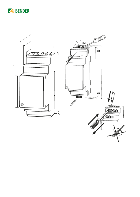
4.1 Installation
Mounting on a DIN rail:
Snap the mounting clip at the rear of the device onto the DIN rail so
that it sits securely
or
Screw fixing:
Use a tool to position the rear mounting clips (a second. mounting clip
is required, see ordering information) so that it protrudes over the
enclosure. Fix the device with two M4 screws, see the following sketch.
isoPV425_D00028_02_M_XXEN/09.2014
15
Installation, connection and commissioning
90 mm
45
67,5
36 mm
31,1
47,5
70,5
2
2
1
2
3
100 mm
116 mm
Zubehör/
Accessory
Dimension diagram, sketch for screw mounting, push-wire terminal
connection:
The front plate cover is easy to open at the lower part marked by an arrow.
16
isoPV425_D00028_02_M_XXEN/09.2014

Installation, connection and commissioning
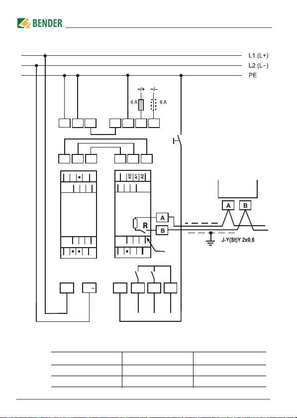
4.2 Connection
Connect the terminals A1 and A2 to the supply voltage according to
IEC 60364-4-43, i.e. the connections are to be protected against short-circuit
by means of a protective device (a 6 A fuse is recommended).
Devices for protection against short-circuit in conformity with IEC 60364-4-43
for the coupling of terminals L1/L2 of AGH420 to the IT system to be monitored can be omitted if the wiring is carried out in such a manner as to reduce
the risk of a short-circuit to a minimum.
Only one ISOMETER® may be controlled via a test/reset button. It is not
allowed to use a parallel connection of several test or reset inputs for testing
multiple ISOMETER®s.
For UL application:
Only use 60/70 °C copper lines!
For UL and CSA applications, it is mandatory to use 5 A fuse for the protection
of the supply voltage.
isoPV425_D00028_02_M_XXEN/09.2014
17
Installation, connection and commissioning
U
S
14
24
11
GND
T/R
A
B
AK2
AK1
E
GND
L1/+
L2/-
L1/+
E
KE A1 A2
AK1AK2
GND
14
24 11
K1 K2
Up
GND AK1 AK2
Up
Up
Up
T/R
isoPV425
AGH420
AK1
AK2
Test / Reset
COM460IP
on
off
L2/
RS-485
E
E
Connect the device as illustrated in the wiring diagram:
18
Requirements for wiring the terminals Up, AK1, GND, AK2:
Cable length Cable type Wire cross section
≤ 0.5 m 1 or 4-core
≤ 5 m 4-core
isoPV425_D00028_02_M_XXEN/09.2014
≥ 0.75mm
2.5mm
2
2
 Loading...