

Page 1
EN
Manual
ISOMETER®
isoNAV685-D-B
Insulation Monitoring Device for IT AC systems
with galvanically connected rectifiers and inverters
and for IT DC systems
isoNAV685-D-B_D00264_03_M_XXEN/06.2017
Page 2

PLEASE READ THIS MANUAL AND ANY ACCOMPANYING DOCUMENTS CAREFULLY AND KEEP THEM IN A SECURE PLACE FOR FUTURE
REFERENCE.
Bender GmbH & Co. KG
Postfach 1161 • 35301 Gruenberg • Germany
Londorfer Straße 65 • 35305 Gruenberg • Germany
Tel.: +49 6401 807-0
Fax: +49 6401 807-259
E-Mail: info@bender.de
Web: www.bender.de
Customer service
Service-Hotline: 0700-BenderHelp (Telephone and Fax)
Carl-Benz-Straße 8 • 35305 Gruenberg • Germany
Tel.:+49 6401 807-760
Fax:+49 6401 807-629
E-Mail:info@bender-service.com
© Bender GmbH & Co. KG
All rights reserved.
Reproduction only with permission
of the publisher.
Subject to change.
Page 3

Table of contents
1. Important information .................................................................... 6
1.1 How to use this manual . . . . . . . . . . . . . . . . . . . . . . . . . . . . . . . . . . . . . . . . . . . . . 6
1.2 Technical support . . . . . . . . . . . . . . . . . . . . . . . . . . . . . . . . . . . . . . . . . . . . . . . . . . 6
1.2.1 First level support . . . . . . . . . . . . . . . . . . . . . . . . . . . . . . . . . . . . . . . . . . . . . . 6
1.2.2 Repair service . . . . . . . . . . . . . . . . . . . . . . . . . . . . . . . . . . . . . . . . . . . . . . . . . . 6
1.2.3 Field service . . . . . . . . . . . . . . . . . . . . . . . . . . . . . . . . . . . . . . . . . . . . . . . . . . . . 7
1.3 Training courses . . . . . . . . . . . . . . . . . . . . . . . . . . . . . . . . . . . . . . . . . . . . . . . . . . . . 7
1.4 Delivery conditions . . . . . . . . . . . . . . . . . . . . . . . . . . . . . . . . . . . . . . . . . . . . . . . . . 7
1.5 Inspection, transport and storage . . . . . . . . . . . . . . . . . . . . . . . . . . . . . . . . . . . 7
1.6 Disposal. . . . . . . . . . . . . . . . . . . . . . . . . . . . . . . . . . . . . . . . . . . . . . . . . . . . . . . . . . . . 7
2. Safety instructions ............................................................................ 8
2.1 General safety instructions. . . . . . . . . . . . . . . . . . . . . . . . . . . . . . . . . . . . . . . . . . 8
2.2 Work activities on electrical installations. . . . . . . . . . . . . . . . . . . . . . . . . . . . . 8
2.3 Device-specific safety information . . . . . . . . . . . . . . . . . . . . . . . . . . . . . . . . . . 8
2.4 Intended use . . . . . . . . . . . . . . . . . . . . . . . . . . . . . . . . . . . . . . . . . . . . . . . . . . . . . . . 9
3. Function ........................................................................................... 10
3.1 Features. . . . . . . . . . . . . . . . . . . . . . . . . . . . . . . . . . . . . . . . . . . . . . . . . . . . . . . . . . . 10
3.2 Product description . . . . . . . . . . . . . . . . . . . . . . . . . . . . . . . . . . . . . . . . . . . . . . . 10
3.3 Functional description . . . . . . . . . . . . . . . . . . . . . . . . . . . . . . . . . . . . . . . . . . . . . 10
3.4 Interfaces . . . . . . . . . . . . . . . . . . . . . . . . . . . . . . . . . . . . . . . . . . . . . . . . . . . . . . . . . 11
3.5 Self test . . . . . . . . . . . . . . . . . . . . . . . . . . . . . . . . . . . . . . . . . . . . . . . . . . . . . . . . . . . 11
4. Device overview .............................................................................. 12
4.1 Dimensions . . . . . . . . . . . . . . . . . . . . . . . . . . . . . . . . . . . . . . . . . . . . . . . . . . . . . . . 12
4.2 Connections and panel . . . . . . . . . . . . . . . . . . . . . . . . . . . . . . . . . . . . . . . . . . . . 13
4.3 Display elements and device buttons . . . . . . . . . . . . . . . . . . . . . . . . . . . . . . 14
6. Connection .......................................................................................16
6.1 Connection requirements . . . . . . . . . . . . . . . . . . . . . . . . . . . . . . . . . . . . . . . . . . 16
6.2 Connection to a 3(N)AC system/system type 3AC . . . . . . . . . . . . . . . . . . .18
6.3 Connect to a frequency converter to monitor in the off state (Offline)18
6.4 Connection to the X1 interface . . . . . . . . . . . . . . . . . . . . . . . . . . . . . . . . . . . . .19
6.5 Connection to the supply voltage . . . . . . . . . . . . . . . . . . . . . . . . . . . . . . . . . .19
6.6 Connection to the Ethernet interface . . . . . . . . . . . . . . . . . . . . . . . . . . . . . . .20
6.7 Connection to the relay 1 interface (11 12 14) . . . . . . . . . . . . . . . . . . . . . . 20
6.8 Connection to the relay 2 interface (21 22 24) . . . . . . . . . . . . . . . . . . . . . . 21
7. Commissioning ............................................................................... 22
7.1 General initial commissioning process . . . . . . . . . . . . . . . . . . . . . . . . . . . . . .22
7.2 Recommissioning. . . . . . . . . . . . . . . . . . . . . . . . . . . . . . . . . . . . . . . . . . . . . . . . . .22
8. Display ..............................................................................................23
8.1 Standard display . . . . . . . . . . . . . . . . . . . . . . . . . . . . . . . . . . . . . . . . . . . . . . . . . . .23
8.2 Fault display (active) . . . . . . . . . . . . . . . . . . . . . . . . . . . . . . . . . . . . . . . . . . . . . . . 23
8.3 Fault display (inactive) . . . . . . . . . . . . . . . . . . . . . . . . . . . . . . . . . . . . . . . . . . . . .24
8.4 Acknowledge fault memory. . . . . . . . . . . . . . . . . . . . . . . . . . . . . . . . . . . . . . . .25
8.5 History memory . . . . . . . . . . . . . . . . . . . . . . . . . . . . . . . . . . . . . . . . . . . . . . . . . . .25
8.6 Initial measurement . . . . . . . . . . . . . . . . . . . . . . . . . . . . . . . . . . . . . . . . . . . . . . .26
9. Menu ................................................................................................. 27
9.1 Menu structure . . . . . . . . . . . . . . . . . . . . . . . . . . . . . . . . . . . . . . . . . . . . . . . . . . . .27
9.2 Operating and navigating . . . . . . . . . . . . . . . . . . . . . . . . . . . . . . . . . . . . . . . . . . 28
9.2.1 Easy operation . . . . . . . . . . . . . . . . . . . . . . . . . . . . . . . . . . . . . . . . . . . . . . . .28
5. Mounting .......................................................................................... 15
5.1 General instructions . . . . . . . . . . . . . . . . . . . . . . . . . . . . . . . . . . . . . . . . . . . . . . . 15
5.2 Screw mounting . . . . . . . . . . . . . . . . . . . . . . . . . . . . . . . . . . . . . . . . . . . . . . . . . . . 15
5.3 DIN rail mounting . . . . . . . . . . . . . . . . . . . . . . . . . . . . . . . . . . . . . . . . . . . . . . . . . 16
3
isoNAV685-D-B_D00264_03_M_XXEN/06.2017
Page 4

Table of contentsTable of contents
10. Settings .......................................................................................... 29
10.1 Settings in the device menu . . . . . . . . . . . . . . . . . . . . . . . . . . . . . . . . . . . . . . 29
10.1 (1.0) Alarm settings . . . . . . . . . . . . . . . . . . . . . . . . . . . . . . . . . . . . . . . . 29
10.1 (1.1) Insulation alarm . . . . . . . . . . . . . . . . . . . . . . . . . . . . . . . . . . . . . . 29
10.1 (1.1.1) Alarm 1 . . . . . . . . . . . . . . . . . . . . . . . . . . . . . . . . . . . . . . . . . . . 29
10.1 (1.1.2) Fault memory . . . . . . . . . . . . . . . . . . . . . . . . . . . . . . . . . . . . . 29
10.1 (1.2) Profile . . . . . . . . . . . . . . . . . . . . . . . . . . . . . . . . . . . . . . . . . . . . . . . 29
10.1 (1.3) System type. . . . . . . . . . . . . . . . . . . . . . . . . . . . . . . . . . . . . . . . . . 29
10.1 (1.4) Device . . . . . . . . . . . . . . . . . . . . . . . . . . . . . . . . . . . . . . . . . . . . . . . 29
10.1 (1.5) T(Start). . . . . . . . . . . . . . . . . . . . . . . . . . . . . . . . . . . . . . . . . . . . . . . 29
10.1 (1.6) Coupling monitoring . . . . . . . . . . . . . . . . . . . . . . . . . . . . . . . . . 29
10.1 (1.7) Inputs . . . . . . . . . . . . . . . . . . . . . . . . . . . . . . . . . . . . . . . . . . . . . . . 30
10.1 (1.7.1) Digital 1 . . . . . . . . . . . . . . . . . . . . . . . . . . . . . . . . . . . . . . . . . . 30
10.1 (1.7.1.1) Mode . . . . . . . . . . . . . . . . . . . . . . . . . . . . . . . . . . . . . . . . . . 30
10.1 (1.7.1.2) t(on) . . . . . . . . . . . . . . . . . . . . . . . . . . . . . . . . . . . . . . . . . . . 30
10.1 (1.7.1.3) t(off) . . . . . . . . . . . . . . . . . . . . . . . . . . . . . . . . . . . . . . . . . . . 30
10.1 (1.7.1.4) Function . . . . . . . . . . . . . . . . . . . . . . . . . . . . . . . . . . . . . . . 30
10.1 (1.7.2) Digital 2 . . . . . . . . . . . . . . . . . . . . . . . . . . . . . . . . . . . . . . . . . . 31
10.1 (1.7.3) Digital 3 . . . . . . . . . . . . . . . . . . . . . . . . . . . . . . . . . . . . . . . . . . 31
10.1 (1.8) Outputs . . . . . . . . . . . . . . . . . . . . . . . . . . . . . . . . . . . . . . . . . . . . . . 31
10.1 (1.8.1) Relay 1. . . . . . . . . . . . . . . . . . . . . . . . . . . . . . . . . . . . . . . . . . . . 31
10.1 (1.8.1.1) TEST . . . . . . . . . . . . . . . . . . . . . . . . . . . . . . . . . . . . . . . . . . . 31
10.1 (1.8.1.2) Relay mode . . . . . . . . . . . . . . . . . . . . . . . . . . . . . . . . . . . . 31
10.1 (1.8.1.3) Function 1 . . . . . . . . . . . . . . . . . . . . . . . . . . . . . . . . . . . . . 31
10.1 (1.8.1.4) Function 2 . . . . . . . . . . . . . . . . . . . . . . . . . . . . . . . . . . . . . 32
10.1 (1.8.1.5) Function 3 . . . . . . . . . . . . . . . . . . . . . . . . . . . . . . . . . . . . . 32
10.1 (1.8.2) Relay 2. . . . . . . . . . . . . . . . . . . . . . . . . . . . . . . . . . . . . . . . . . . . 32
10.1 (1.8.3) Digital 1 . . . . . . . . . . . . . . . . . . . . . . . . . . . . . . . . . . . . . . . . . . 32
10.1 (1.8.3.1) Mode . . . . . . . . . . . . . . . . . . . . . . . . . . . . . . . . . . . . . . . . . . 32
10.1 (1.8.3.2) Function 1 . . . . . . . . . . . . . . . . . . . . . . . . . . . . . . . . . . . . . 32
10.1 (1.8.3.3) Function 2 . . . . . . . . . . . . . . . . . . . . . . . . . . . . . . . . . . . . . 32
10.1 (1.8.3.4) Function 3 . . . . . . . . . . . . . . . . . . . . . . . . . . . . . . . . . . . . . 32
10.1 (1.8.4) Digital 2 . . . . . . . . . . . . . . . . . . . . . . . . . . . . . . . . . . . . . . . . . . 32
10.1 (1.8.5) Buzzer . . . . . . . . . . . . . . . . . . . . . . . . . . . . . . . . . . . . . . . . . . . . 33
10.1 (1.8.5.1) TEST . . . . . . . . . . . . . . . . . . . . . . . . . . . . . . . . . . . . . . . . . . . 33
10.1 (1.8.5.2) Function 1 . . . . . . . . . . . . . . . . . . . . . . . . . . . . . . . . . . . . . 33
10.1 (1.8.5.3) Function 2 . . . . . . . . . . . . . . . . . . . . . . . . . . . . . . . . . . . . . 33
10.1 (1.8.5.4) Function 3 . . . . . . . . . . . . . . . . . . . . . . . . . . . . . . . . . . . . . 33
10.1 (2.0) Data measured values . . . . . . . . . . . . . . . . . . . . . . . . . . . . . . . . . . 33
10.1 (3.0) Control . . . . . . . . . . . . . . . . . . . . . . . . . . . . . . . . . . . . . . . . . . . . . . . . .33
10.1 (4.0) History . . . . . . . . . . . . . . . . . . . . . . . . . . . . . . . . . . . . . . . . . . . . . . . . .33
10.1 (5.0) Device settings . . . . . . . . . . . . . . . . . . . . . . . . . . . . . . . . . . . . . . . . .33
10.1 (5.1) Language . . . . . . . . . . . . . . . . . . . . . . . . . . . . . . . . . . . . . . . . . . . . 33
10.1 (5.2) Clock. . . . . . . . . . . . . . . . . . . . . . . . . . . . . . . . . . . . . . . . . . . . . . . . . 33
10.1 (5.2.1) Time . . . . . . . . . . . . . . . . . . . . . . . . . . . . . . . . . . . . . . . . . . . . . . 33
10.1 (5.2.2) Format (time). . . . . . . . . . . . . . . . . . . . . . . . . . . . . . . . . . . . . . 33
10.1 (5.2.3) Summer time. . . . . . . . . . . . . . . . . . . . . . . . . . . . . . . . . . . . . . 34
10.1 (5.2.4) Date . . . . . . . . . . . . . . . . . . . . . . . . . . . . . . . . . . . . . . . . . . . . . . 34
10.1 (5.2.5) Format (date). . . . . . . . . . . . . . . . . . . . . . . . . . . . . . . . . . . . . . 34
10.1 (5.2.6) NTP . . . . . . . . . . . . . . . . . . . . . . . . . . . . . . . . . . . . . . . . . . . . . . . 34
10.1 (5.2.7) NTP server. . . . . . . . . . . . . . . . . . . . . . . . . . . . . . . . . . . . . . . . . 34
10.1 (5.2.8) UTC . . . . . . . . . . . . . . . . . . . . . . . . . . . . . . . . . . . . . . . . . . . . . . . 34
10.1 (5.3) Interface . . . . . . . . . . . . . . . . . . . . . . . . . . . . . . . . . . . . . . . . . . . . . 34
10.1 (5.3.1) Write access . . . . . . . . . . . . . . . . . . . . . . . . . . . . . . . . . . . . . . . 34
10.1 (5.3.2) Ethernet. . . . . . . . . . . . . . . . . . . . . . . . . . . . . . . . . . . . . . . . . . . 34
10.1 (5.3.2.1) DHCP . . . . . . . . . . . . . . . . . . . . . . . . . . . . . . . . . . . . . . . . . . 34
10.1 (5.3.2.2) IP . . . . . . . . . . . . . . . . . . . . . . . . . . . . . . . . . . . . . . . . . . . . . . 35
10.1 (5.3.2.3) SN . . . . . . . . . . . . . . . . . . . . . . . . . . . . . . . . . . . . . . . . . . . . . 35
10.1 (5.3.2.4) Std. GW . . . . . . . . . . . . . . . . . . . . . . . . . . . . . . . . . . . . . . . . 35
10.1 (5.3.2.5) DNS server . . . . . . . . . . . . . . . . . . . . . . . . . . . . . . . . . . . . . 35
10.1 (5.3.2.6) Domain . . . . . . . . . . . . . . . . . . . . . . . . . . . . . . . . . . . . . . . . 35
10.1 (5.3.3) BCOM . . . . . . . . . . . . . . . . . . . . . . . . . . . . . . . . . . . . . . . . . . . . . 35
10.1 (5.3.3.1) System name. . . . . . . . . . . . . . . . . . . . . . . . . . . . . . . . . . . 35
10.1 (5.3.3.2) Subsystem . . . . . . . . . . . . . . . . . . . . . . . . . . . . . . . . . . . . . 35
10.1 (5.3.3.3) Device address . . . . . . . . . . . . . . . . . . . . . . . . . . . . . . . . . 35
10.1 (5.3.3.4) Timeout. . . . . . . . . . . . . . . . . . . . . . . . . . . . . . . . . . . . . . . . 35
10.1 (5.3.3.5) TTL for subscription . . . . . . . . . . . . . . . . . . . . . . . . . . . . 35
10.1 (5.3.4) Modbus TCP. . . . . . . . . . . . . . . . . . . . . . . . . . . . . . . . . . . . . . . 35
10.1 (5.3.4.1) Port 502. . . . . . . . . . . . . . . . . . . . . . . . . . . . . . . . . . . . . . . . 35
10.1 (5.3.5) BMS bus. . . . . . . . . . . . . . . . . . . . . . . . . . . . . . . . . . . . . . . . . . . 35
10.1 (5.4) Display . . . . . . . . . . . . . . . . . . . . . . . . . . . . . . . . . . . . . . . . . . . . . . . 35
10.1 (5.4.1) Brightness . . . . . . . . . . . . . . . . . . . . . . . . . . . . . . . . . . . . . . . . . 35
10.1 (5.5) Password . . . . . . . . . . . . . . . . . . . . . . . . . . . . . . . . . . . . . . . . . . . . . 35
10.1 (5.5.1) Password. . . . . . . . . . . . . . . . . . . . . . . . . . . . . . . . . . . . . . . . . . 35
10.1 (5.5.2) Status . . . . . . . . . . . . . . . . . . . . . . . . . . . . . . . . . . . . . . . . . . . . . 36
10.1 (5.6) Commissioning . . . . . . . . . . . . . . . . . . . . . . . . . . . . . . . . . . . . . . . 36
10.1 (5.7) Data backup. . . . . . . . . . . . . . . . . . . . . . . . . . . . . . . . . . . . . . . . . . 36
10.1 (5.8) Service . . . . . . . . . . . . . . . . . . . . . . . . . . . . . . . . . . . . . . . . . . . . . . . 36
10.1 (6.0) Info . . . . . . . . . . . . . . . . . . . . . . . . . . . . . . . . . . . . . . . . . . . . . . . . . . . .36
4
isoNAV685-D-B_D00264_03_M_XXEN/06.2017
Page 5

Table of contentsTable of contents
11. Device communication ............................................................... 37
11.1 Ethernet interface . . . . . . . . . . . . . . . . . . . . . . . . . . . . . . . . . . . . . . . . . . . . . . . . 37
11.2 BCOM. . . . . . . . . . . . . . . . . . . . . . . . . . . . . . . . . . . . . . . . . . . . . . . . . . . . . . . . . . . . 37
11.3 Modbus TCP . . . . . . . . . . . . . . . . . . . . . . . . . . . . . . . . . . . . . . . . . . . . . . . . . . . . . 37
11.4 Web server . . . . . . . . . . . . . . . . . . . . . . . . . . . . . . . . . . . . . . . . . . . . . . . . . . . . . . . 38
12. Diagrams ........................................................................................ 41
12.1 Response time profile offline . . . . . . . . . . . . . . . . . . . . . . . . . . . . . . . . . . . . . 41
12.2 Relative uncertainty . . . . . . . . . . . . . . . . . . . . . . . . . . . . . . . . . . . . . . . . . . . . . . 41
13. Alarm messages ............................................................................ 42
14. Factory settings ............................................................................ 43
15. Technical data ............................................................................... 44
15.1 Tabular data . . . . . . . . . . . . . . . . . . . . . . . . . . . . . . . . . . . . . . . . . . . . . . . . . . . . . 44
15.2 Standards and certifications . . . . . . . . . . . . . . . . . . . . . . . . . . . . . . . . . . . . . . 46
15.3 Ordering details . . . . . . . . . . . . . . . . . . . . . . . . . . . . . . . . . . . . . . . . . . . . . . . . . . 47
16. Glossary .......................................................................................... 48
17. Modbus settings ...........................................................................49
17.1 General information . . . . . . . . . . . . . . . . . . . . . . . . . . . . . . . . . . . . . . . . . . . . . .49
17.2 Data access by means of Modbus/TCP-Protokoll . . . . . . . . . . . . . . . . . . .49
17.2.1 Exception code . . . . . . . . . . . . . . . . . . . . . . . . . . . . . . . . . . . . . . . . . . . . . . .49
17.2.2 Modbus request . . . . . . . . . . . . . . . . . . . . . . . . . . . . . . . . . . . . . . . . . . . . . .49
17.2.3 Modbus response . . . . . . . . . . . . . . . . . . . . . . . . . . . . . . . . . . . . . . . . . . . . .50
17.2.4 Structure of exception code . . . . . . . . . . . . . . . . . . . . . . . . . . . . . . . . . . .50
17.3 Measuring value information. . . . . . . . . . . . . . . . . . . . . . . . . . . . . . . . . . . . . .50
17.3.1 High-byte test status . . . . . . . . . . . . . . . . . . . . . . . . . . . . . . . . . . . . . . . . . .50
17.3.2 Low-byte alarm status . . . . . . . . . . . . . . . . . . . . . . . . . . . . . . . . . . . . . . . . .50
17.3.3 High-byte range . . . . . . . . . . . . . . . . . . . . . . . . . . . . . . . . . . . . . . . . . . . . . .50
17.3.4 Low-byte unit . . . . . . . . . . . . . . . . . . . . . . . . . . . . . . . . . . . . . . . . . . . . . . . . .51
17.4 Modbus register assignment . . . . . . . . . . . . . . . . . . . . . . . . . . . . . . . . . . . . . .52
Index ........................................................................................................60
5
isoNAV685-D-B_D00264_03_M_XXEN/06.2017
Page 6
1. Important information
DANGER
WARNING
CAUTION
Important information
1.1 How to use this manual
This manual is intended for qualified personnel working in electrical engineering and electronics!
Always keep this manual within easy reach for future reference.
To make it easier for you to understand and revisit certain sections in this manual, we
have used symbols to identify important instructions and information. The meaning of
these symbols is explained below:
This signal word indicates that there is a high risk of danger that will result in electrocution or serious injury if not avoided.
This signal word indicates a medium risk of danger that can lead to
death or serious injury if not avoided.
1.2 Technical support
For commissioning and troubleshooting Bender offers you:
1.2.1 First level support
Technical support by phone or e-mail for all Bender products
• Questions concerning specific customer applications
• Commissioning
• Troubleshooting
Telephone: +49 6401 807-760*
Fax: +49 6401 807-259
In Germany only: 0700BenderHelp (Tel. and Fax)
E-mail: support@bender-service.de
1.2.2 Repair service
Repair, calibration, update and replacement service for Bender products
• Repairing, calibrating, testing and analysing Bender products
• Hardware and software update for Bender devices
• Delivery of replacement devices in the event of faulty or incorrectly delivered Bender devices
• Extended guarantee for Bender devices, which includes an in-house repair service or
replacement devices at no extra cost
This signal word indicates a low level risk that can result in minor or moderate injury or damage to property if not avoided.
This symbol denotes information intended to assist the user in making
optimum use of the product.
6
Telephone: +49 6401 807-780** (technical issues)
+49 6401 807-784**, -785** (sales)
Fax: +49 6401 807-789
E-mail: repair@bender-service.de
Please send the devices for repair to the following address:
Bender GmbH, Repair-Service,
Londorfer Strasse 65,
35305 Grünberg
isoNAV685-D-B_D00264_03_M_XXEN/06.2017
Page 7

Important informationImportant information
1.2.3 Field service
On-site service for all Bender products
• Commissioning, parameter setting, maintenance, troubleshooting for Bender products
• Analysis of the electrical installation in the building (power quality test, EMC test,
thermography)
• Training courses for customers
Telephone: +49 6401 807-752**, -762 **(technical issues)
+49 6401 807-753** (sales)
Fax: +49 6401 807-759
E-mail: fieldservice@bender-service.de
Internet: www.bender-de.com
*Available from 7.00 a.m. to 8.00 p.m. 365 days a year (CET/UTC+1)
**Mo-Thu 7.00 a.m. - 8.00 p.m., Fr 7.00 a.m. - 13.00 p.m.
1.3 Training courses
Bender is happy to provide training regarding the use of test equipment.
The dates of training courses and workshops can be found on the Internet at
www.bender-de.com -> Know-how -> Seminars.
1.4 Delivery conditions
Bender sale and delivery conditions apply.
For software products the "Softwareklausel zur Überlassung von Standard-Software als
Teil von Lieferungen, Ergänzung und Änderung der Allgemeinen Lieferbedingungen für
Erzeugnisse und Leistungen der Elektroindustrie" (software clause in respect of the licensing of standard software as part of deliveries, modifications and changes to general delivery conditions for products and services in the electrical industry) set out by the ZVEI
(Zentralverband Elektrotechnik- und Elektronikindustrie e. V.) (German Electrical and
Electronic Manufacturer's Association) also applies.
Sale and delivery conditions can be obtained from Bender in printed or electronic format.
1.6 Disposal
Abide by the national regulations and laws governing the disposal of this device. Ask
your supplier if you are not sure how to dispose of the old equipment.
The directive on waste electrical and electronic equipment (WEEE directive) and the directive on the restriction of certain hazardous substances in electrical and electronic
equipment (RoHS directive) apply in the European Community. In Germany, these policies are implemented through the "Electrical and Electronic Equipment Act" (ElektroG).
According to this, the following applies:
• Electrical and electronic equipment are not part of household waste.
• Batteries and accumulators are not part of household waste and must be disposed
of in accordance with the regulations.
• Old electrical and electronic equipment from users other than private households
which was introduced to the market after 13 August 2005 must be taken back by the
manufacturer and disposed of properly.
For more information on the disposal of Bender devices, refer to our homepage at
www.bender-de.com -> Service & support.
1.5 Inspection, transport and storage
The devices must only be stored in areas where they are protected from dust, damp, and
spray and dripping water, and in which the specified storage temperatures can be ensured.
7
isoNAV685-D-B_D00264_03_M_XXEN/06.2017
Page 8
2. Safety instructions
DANGER
WARNING
CAUTION
Safety instructions
2.1 General safety instructions
Part of the device documentation in addition to this manual is the enclosed "Safety instructions for Bender products".
2.2 Work activities on electrical installations
Only qualified personnel are permitted to carry out the work necessary
to install, commission and run a device or system.
Risk of electrocution due to electric shock!
Touching live parts of the system carries the risk of:
• An electric shock
• Damage to the electrical installation
• Destruction of the device
Before installing and connecting the device, make sure that the installation has been de-energised. Observe the rules for working on elec-
trical installations.
If the device is used outside the Federal Republic of Germany, the applicable local standards and regulations must be complied with. The European standard EN 50110 can be
used as a guide.
2.3 Device-specific safety information
Make sure that the basic settings meet the requirements of the IT system.
Children and unauthorised persons must not have access to or contact
with the ISOMETER®.
Make sure that the operating voltage is correct!
Prior to insulation and voltage tests, the ISOMETER® must be disconnected
from the IT system for the duration of the test. In order to check the correct
connection of the device, a functional test has to be carried out before starting the system.
In the event of an alarm message of the ISOMETER®, the insulation fault
should be eliminated as quickly as possible.
If the ISOMETER® is installed inside a control cabinet, the insulation fault
message must be audible and/or visible to attract attention.
When using ISOMETER®s in IT systems, make sure that only one active
ISOMETER® is connected in each interconnected system. If IT systems are
interconnected via coupling switches, make sure that ISOMETER®s not
currently used are disconnected from the IT system and deactivated. IT
systems coupled via diodes or capacitances may also influence the insulation monitoring process so that a central control of the different
ISOMETER®s is required.
8
isoNAV685-D-B_D00264_03_M_XXEN/06.2017
Page 9

Prevent measurement errors!
When a monitored IT system contains galvanically coupled DC circuits, an
insulation fault can only be detected correctly if the rectifier valves (e.g.
rectifier diode, thyristors, IGBTs, frequency inverters, …) carry a minimum
current of > 10 mA.
Safety instructionsSafety instructions
2.4 Intended use
Only qualified personnel are permitted to carry out the work necessary
to install, commission and run a device or system.
Unspecified frequency range
When connecting to an IT system with frequency components below the
specified frequency range, the response times and response values may
differ from the indicated technical data. However, depending on the application and the selected measurement method, continuous insulation
monitoring is also possible in this frequency range.
There is no influence on the insulation monitoring for IT systems with frequency components above the specified frequency range, e.g. within the
range of typical switching frequencies of frequency inverters (2…20 kHz).
The ISOMETER® isoNAV685-D-B monitors the insulation resistance of loads that are
switched off. These loads, which are temporarily or mostly switched off, are powered by
TN, TT or IT systems.
The internal mains switch has a circuit capacity of AC 0…690 V and DC 0…1000 V.
Due to the separate supply voltage, de-energised systems can also be monitored. The
maximum permissible system leakage capacitance is 150 µF.
Intended use also implies:
• The observation of all information in the operating manual
• Compliance with test intervals
In order to meet the requirements of applicable standards, customised parameter settings must be made on the equipment in order to adapt it to local equipment and operating conditions. Please heed the limits of the area of application indicated in the
technical specifications.
Any other use than that described in this manual is regarded as improper.
9
isoNAV685-D-B_D00264_03_M_XXEN/06.2017
Page 10

3. Function
*
Function
3.1 Features
• ISOMETER® to monitor the insulation resistance in systems that are switched off.
• Automatic adaptation to the existing system leakage capacitance.
• measurement method.
• An adjustable response value in the range 1 k…10 M
(factory setting = 50 k).
• High-resolution graphic LC display for excellent readability and recording of the
device status.
• Ground fault monitoring.
• Automatic device self test.
• History memory with real-time clock (buffer for three days) for storing 1023 alarm
messages with date and time.
• Freely programmable digital inputs and outputs.
• Remote setting of certain parameters via Internet
(Option; COMTRAXX® Gateway).
• Worldwide remote diagnosis via Internet.
• Modbus TCP, web server and BCOM.<
3.2 Product description
The ISOMETER® isoNAV685-D-B is an insulation monitoring device for IT systems in accordance with IEC 61557-8. It is universally applicable in TN, TT or IT systems that are
switched off.
3.3 Functional description
The insulation monitoring device ISOMETER® isoNAV685-D-B monitors the entire insulation resistance of systems that are switched off and triggers an alarm when the insulation
resistance value falls below a preset response value.
The insulation resistance of the L1, L2 and L3 coupling paths is measured sequentially.
This means that faults are not only measured, but they can also be localized or located.
The test time may vary, e.g. it may be longer, depending on the leakage capacitance.
To obtain a measurement the device has to be connected between the IT system (unearthed system) and the protective earth conductor (PE). A measuring current in the A
range is superimposed onto the system which is recorded and evaluated by a micro-controlled measuring circuit. The measuring time is dependent on the selected measurement profiles, the system leakage capacitance, the insulation resistance and possible
system-related disturbances.
The response values and other parameters are set using a commissioning wizard as well
as via different setup menus using the device buttons and a high-resolution graphical LC
display. The selected settings are stored in a permanent fail-safe memory. Different languages can be selected for the setup menus as well as the messages indicated on the display. The device utilises a clock for storing fault messages and events in a history memory
with time and date stamp. The settings can be protected against unauthorised modifications by entering a password. To ensure proper functioning of connection monitoring,
the device requires the setting of the system type 3AC and the
appropriate terminals
L1/+, L2, L3/-.
prescribed wiring of the
10
isoNAV685-D-B_D00264_03_M_XXEN/06.2017
Page 11
FunctionFunction
TEST
√ Measurement
Coupling
Earth connection
Outputs
33 %
√
The insulation monitoring device is able to measure the insulation resistance reliably and
precisely in all common IT systems (unearthed systems). Due to various applications, system types, operating conditions, application of variable-speed drives, high system leakage capacitances etc., the measurement technique must be able to meet varying
requ irements in order to ensure an op timised respons e time an d relati ve uncer tainty. Different measurement profiles which can be selected from a setup menu allow optimum
adaptation of the measurement technique to the specific application.
If the resistance value below a set response value R
vated, the LED ALARM 1 (alarm at L1 or L2) or ALARM 2 (alarm at L3) lights and the LCD
shows the measured value. If the fault memory is activated, the fault message will be
stored. Pressing the RESET button resets the insulation fault message, provided that the
current insulation resistance displayed at the time of resetting is at least 25 % above the
actual response value. As additional Information, the quality of the measuring signal and
the time required to update the measured value are shown on the display.
, the associated alarm relay is acti-
an
3.4 Interfaces
• Communication protocol Modbus TCP
• BCOM for Bender device communication via Ethernet
• Integrated web server for reading out measured values and for parameter setting
3.5 Self test
After switching on the supply voltage, the ISOMETER® automatically and continuously
checks all internal measuring functions, the components of the process control such as
the data and parameter memory, as well as the connections to the IT system and earth.
The self test can also be activated manually by means of the test button to check the functions of the relays (depending on the configuration) or it can be selected via the "Control"
menu (refer to “Control” on page 33).
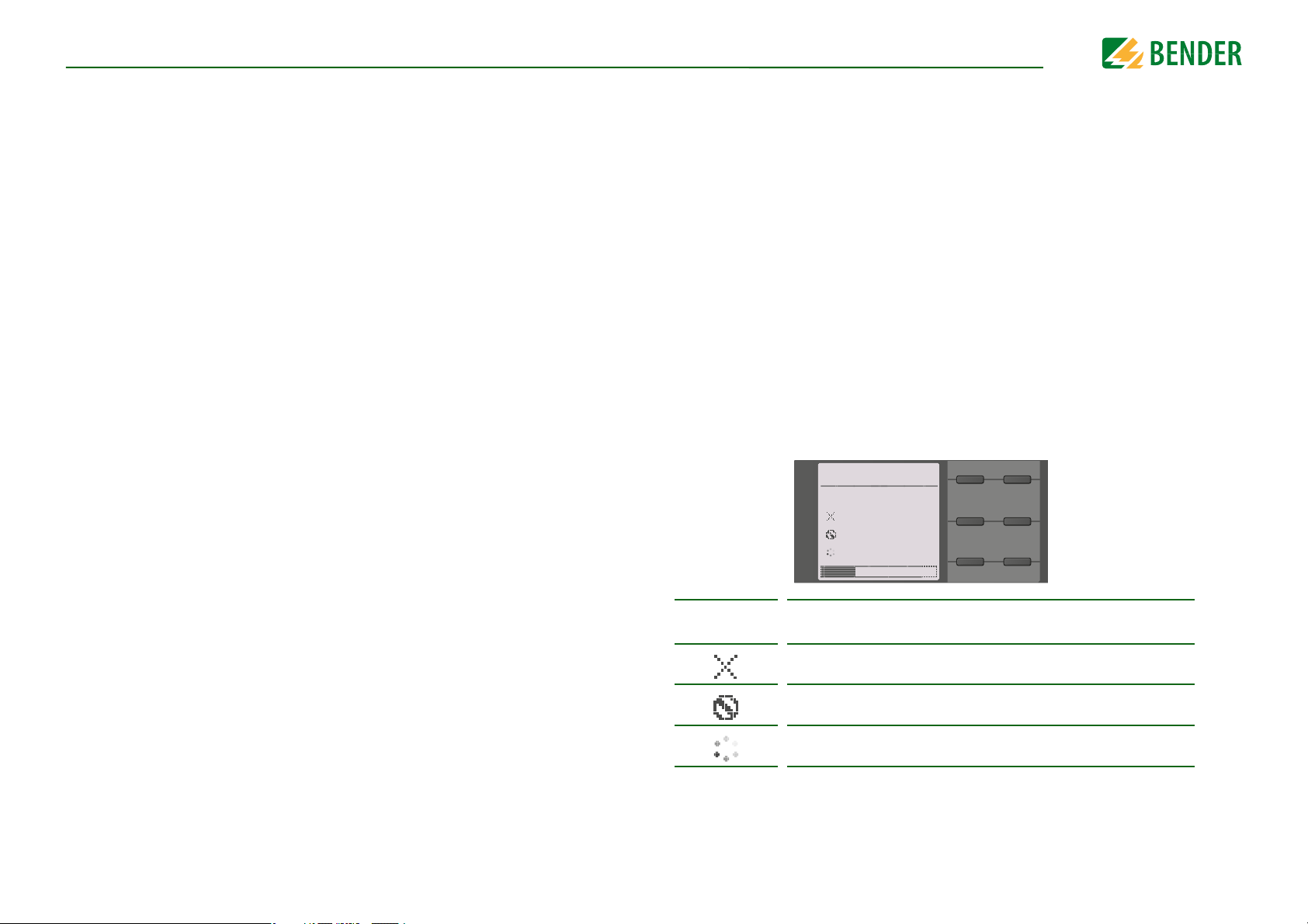
The progress of the manual self test is shown on the LC display by a bar graph. Depending
on the conditions in the IT system being monitored, the self test is completed after
15…20 seconds. The device then returns to the standard mode (measurement mode)
and the actual measured value will be displayed after the measuring time has expired.
The display shows the message
ured (refer to “Initial measurement” on page 26).
If a fault is detected during the self test, the respective LEDs of the device light (refer to
“Alarm messages” on page 42). In addition, the respective message will be indicated on
the display and a previously programmed output will provide the respective signal.
Initial measurement
until the first valid value is meas-
11
The test has been run and the result was positive.
The test has been run and the result was negative.
The test is not available and is not carried out
(e.g. due to specific device settings).
The test is running.
isoNAV685-D-B_D00264_03_M_XXEN/06.2017
Page 12

4. Device overview
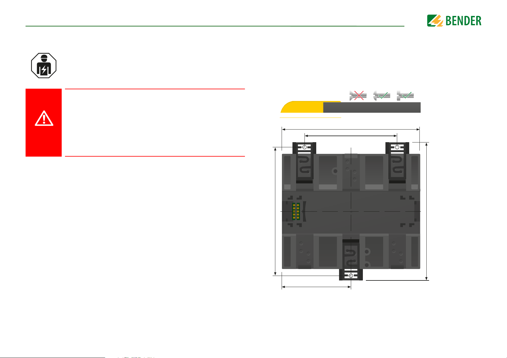
4.1 Dimensions
108 mm
110 mm
mm 39
12
isoNAV685-D-B_D00264_03_M_XXEN/06.2017
Page 13
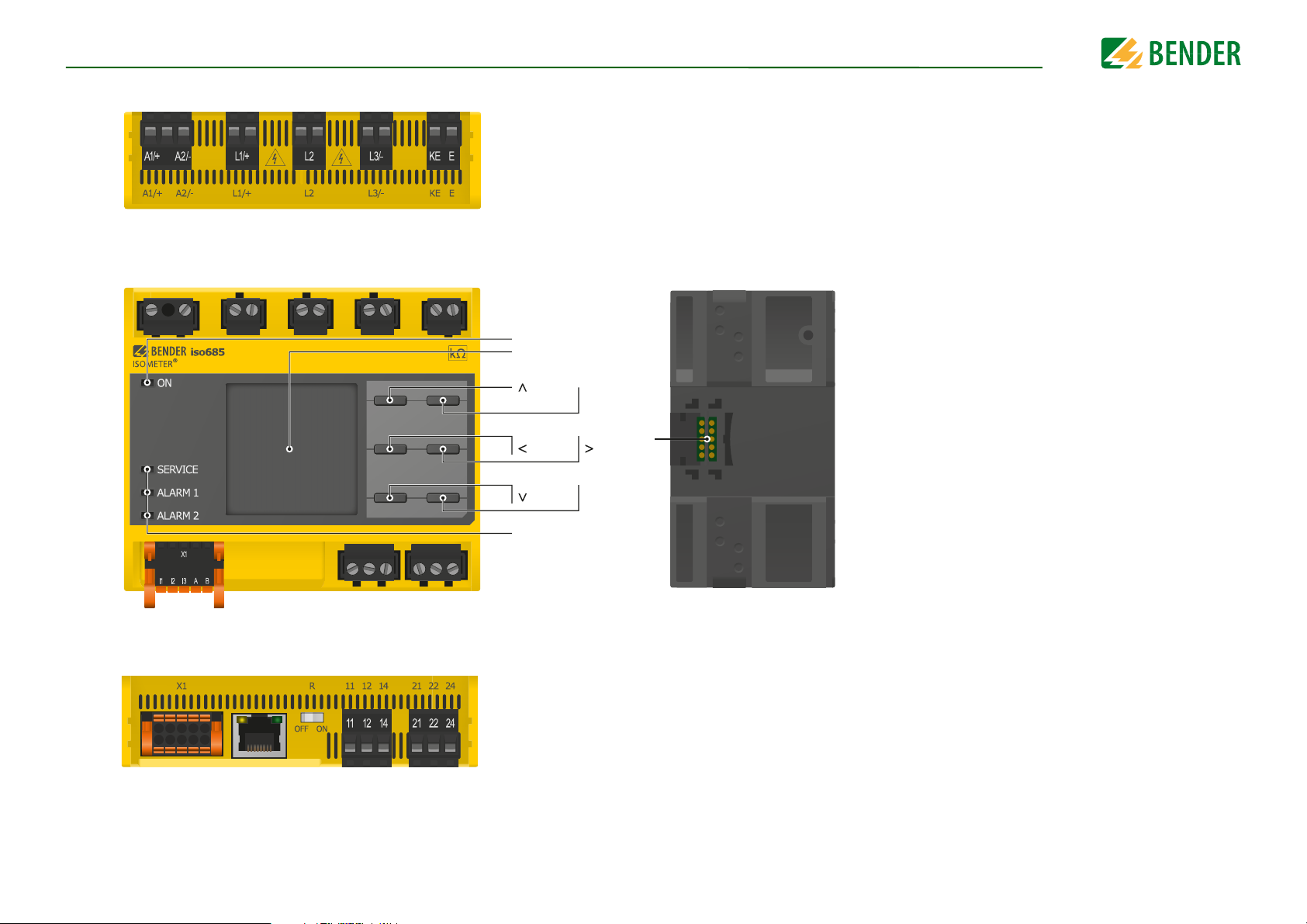
Device overview
A1/+, A2/- Connection to the power supply voltage U
s
L1/+ Connection to the IT system to be monitored
L2 Connection to the IT system to be monitored
L3/- Connection to the IT system to be monitored
KE, E Connection to PE
To p
X3 Optional expansion module for Bender devices (e. g. BB-Bus)
ETH
X1 Digital interface
ETH Ethernet interface
R Selectable resistance R
11 12 14 Connector for alarm relay 1
21 22 24 Connector for alarm relay 2
Bottom
4.2 Connections and panel
ON
Display
MENU
ESC
13
RESET
DATA
LEDs: SERVICE,
ALARM 1, ALARM 2
TEST
INFO
OK
X3
isoNAV685-D-B_D00264_03_M_XXEN/06.2017
Page 14
Device overviewDevice overview
1
7
8
9
10
11
2
3
4
5
6
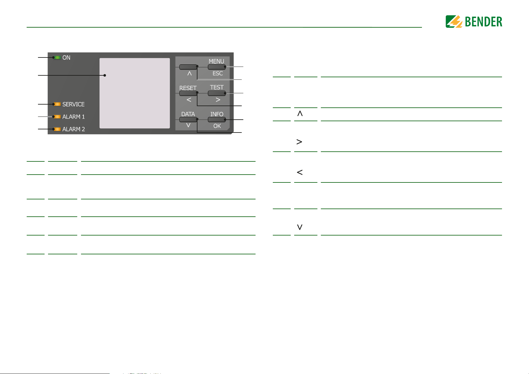
4.3 Display elements and device buttons
Display elements
1 ON The LED "ON" lights when the device is turned on.
The device display shows information regarding the device and the
2
3
4
5
SERVICE
ALARM 1
ALARM 2
measurements.
Other information is available in the chapter “Display” from page 23.
The LED "SERVICE" lights when there is either a device fault or a connection fault, or when the device is in maintenance mode.
The LED "ALARM 1" lights when the insulation resistance of the IT system
falls below the set response value R
The LED "ALARM 2" lights when the insulation resistance of the IT system
falls below the set response value R
an1
an2
.
.
Device buttons
You can adjust the device settings in the respective menu using the menu buttons.
Depending on the menu entry, one of the options displayed below is assigned to the
buttons.
MENU Opens the device menu.
6
7
8
9
10
11
ESC
TEST
RESET
Info
OK
DATA
Cancels the current process or
navigates one step back in the device menu.
Navigates up in a list or increases a value.
Starts the device self test.
Navigates forwards (e.g. to the next setting step) or
selects a parameter.
Resets alarms.
Navigates backwards (e.g. to the previous setting step) or
selects a parameter.
Shows information.
Confirms an action or a selection.
Indicates data and values.
Navigates down in a list or reduces a value.
14
isoNAV685-D-B_D00264_03_M_XXEN/06.2017
Page 15
5. Mounting
DANGER
72 mm
108 mm
54 mm
100 mm
107,3 m m
Mounting
5.1 General instructions
Only qualified personnel are permitted to carry out the work necessary
to install, commission and run a device or system.
Risk of electrocution due to electric shock!
Touching live parts of the system carries the risk of:
• An electric shock
• Damage to the electrical installation
• Destruction of the device
Before installing and connecting the device, make sure that the installation has been de-energised. Observe the rules for working on elec-
trical installations.
5.2 Screw mounting
18. Fix the three mounting clips delivered with the device (two of them packed separately) manually or using a tool, as illustrated below.
19. Drill the mounting holes for the M4 thread according to the dimensioned drilling template.
20. Fix the ISOMETER® using three M4 screws.
15
isoNAV685-D-B_D00264_03_M_XXEN/06.2017
Page 16
Connection
DANGER
DANGER
DANGER
WARNING
6. Connection
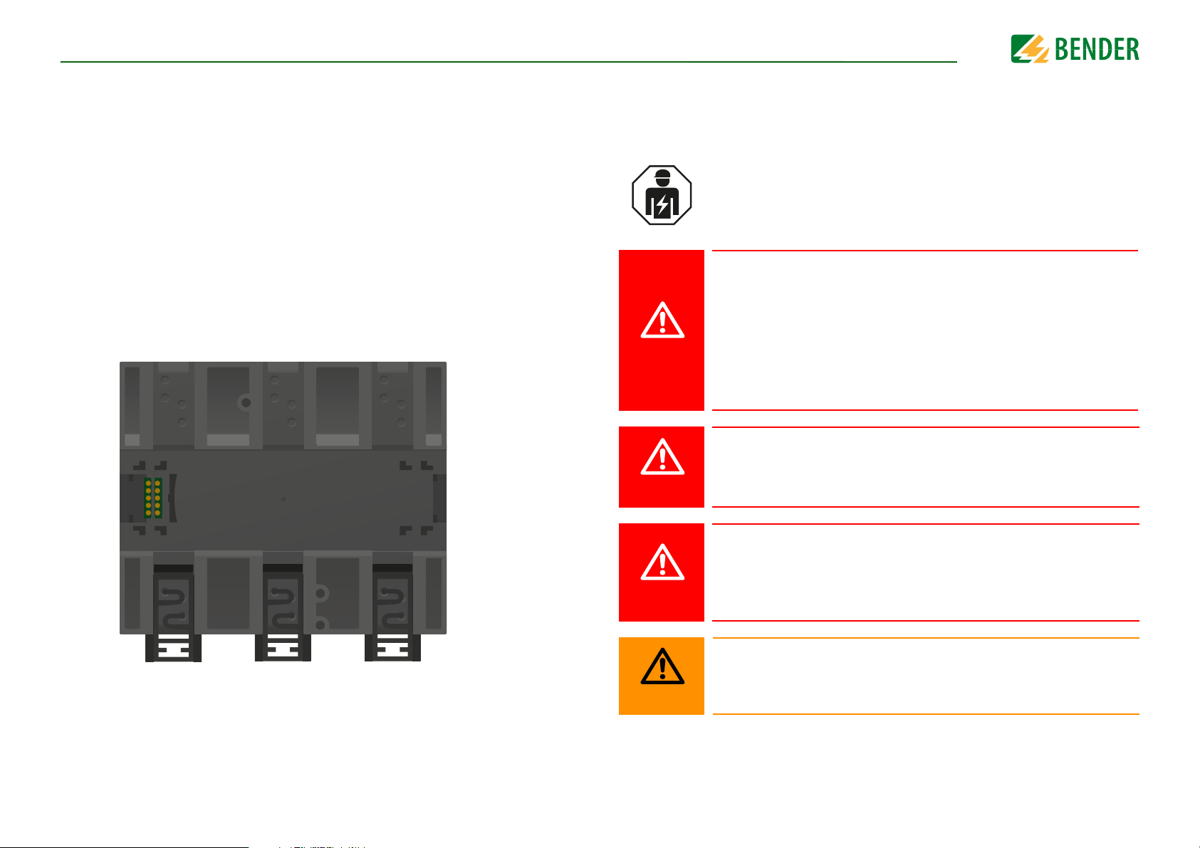
5.3 DIN rail mounting
1. Fix the three mounting clips delivered with the device (two of them packed separately) manually or using a tool, as illustrated below.
2. Fix the ISOMETER® onto the DIN rail until it snaps into place.
6.1 Connection requirements
Consider the minimum distance to adjacent devices:
lateral 0 mm, top 20 mm, bottom 20 mm.
Only qualified personnel are permitted to carry out the work necessary
to install, commission and run a device or system.
Risk of electrocution due to electric shock!
Touching live parts of the system carries the risk of:
• An electric shock
• Damage to the electrical installation
• Destruction of the device
Before installing and connecting the device, make sure that the installation has been de-energised. Observe the rules for working on elec-
trical installations.
Risk of electric shock!
Nominal voltages up to 1000 V may be present on the terminals L1/+ to
L3/- which can be lethal. Make sure the terminal covers are properly
mounted and clicked in before putting the device into operation.
16
Risk of electric shock!
High voltage is applied at the terminals, which in case of direct contact
can be life-threatening. If the terminals L1/+, L2, L3/- of the device are connected to a live IT system, the terminals E and KE must not be disconnected
from the protective conductor (PE).
Warning of insulation monitoring devices that do not work correctly!
Connect the terminals KE and E individually to the protective earth conductor PE.
isoNAV685-D-B_D00264_03_M_XXEN/06.2017
Page 17
ConnectionConnection
CAUTION
CAUTION
CAUTION
CAUTION
CAUTION
Provide line protection!
According to DIN VDE 0100-430, a line protection shall be provided for the
supply voltage.
Risk of injury from sharp-edged terminals!
Risk of lacerations.
Touch the enclosure and the terminals with due care.
Ensure disconnection from the IT system!
When insulation or voltage tests are to be carried out, the device must be
isolated from the system for the test period. Otherwise the device may be
damaged.
Risk of property damage due to unprofessional installation!
If more than one insulation monitoring device is connected to a conductively connected system, the system can be damaged. If several devices
are connected, the device does not function and does not signal insulation faults. Make sure that only one insulation monitoring device is connected in each conductively connected system.
Prevent measurement errors!
When an AC system being monitored contains galvanically coupled DC
circuits, take into consideration that: an insulation fault can only be detected correctly when the rectifier valves carry a minimum current of
>10 mA.
For UL applications:
Use 60/70 °C copper lines only!
For UL and CSA applications, the supply voltage must be protected via 5 A
fuses.
17
Risk of property damage due to unprofessional installation!
The connecting lines L1/+, L2, L3/- to the system to be monitored must be
carried out as spur lines. Inadmissible load current can result in damage
to property and personal injury. Do not apply any load current to the terminals.
Check proper connection!
Prior to commissioning of the installation, check that the device has been
properly connected and check the device functions. Perform a functional
test using an earth fault via a suitable resistance.
isoNAV685-D-B_D00264_03_M_XXEN/06.2017
Page 18
ConnectionConnection
WARNING
L1
L2
L3
N
PE
U
S
6A
U
n
PE
M
DC+
DC-
AC
KE E
IT System
OK
230 kΩ
R(an) 4 0kΩ/10kΩ
OK
230 kΩ
L1/+ L2 L3/-
L1/+ L2 L3/- KE E
3
=
3
=
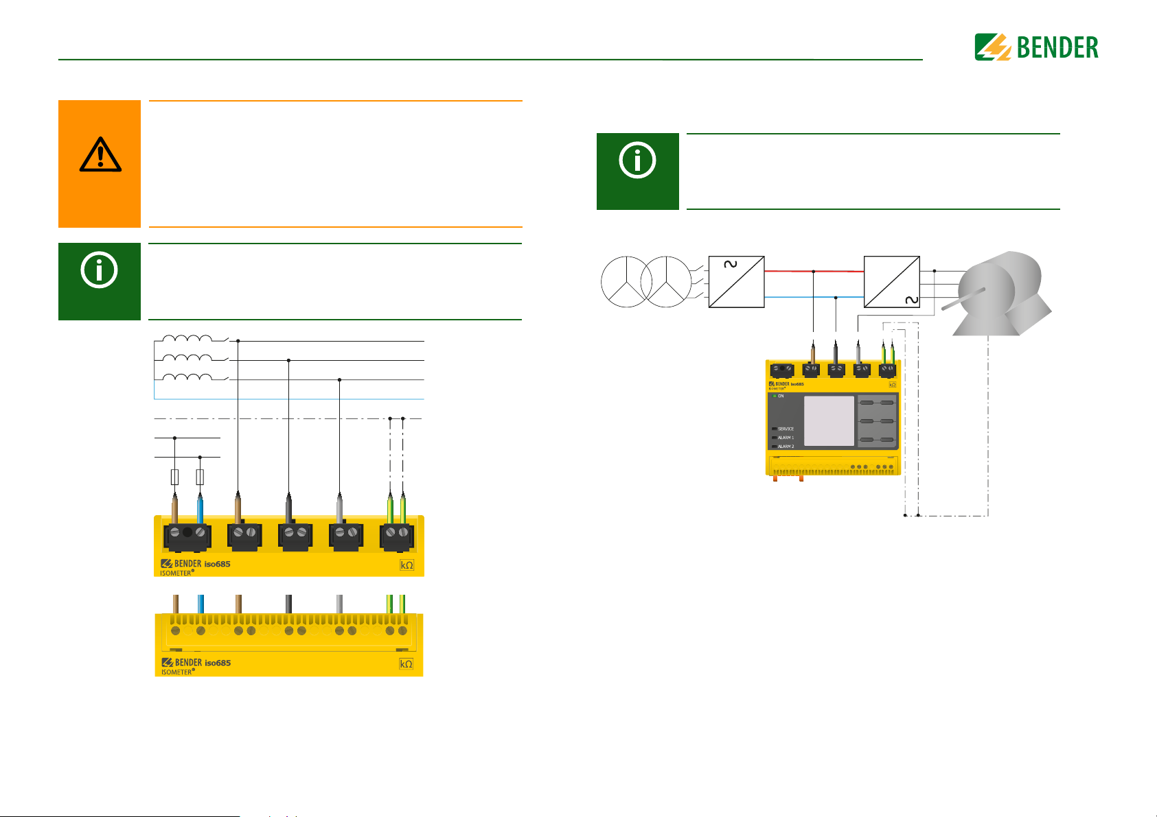
6.2 Connection to a 3(N)AC system/system type 3AC
Risk of injury, fire and damage to property due to a short circuit!
According to DIN VDE 0100-430, devices used to protect against a
short circuit when terminals L1/+, L2 und L3/- are coupled to the IT
system to be monitored can be omitted if the wiring is carried out
in such a manner as to reduce the risk of a short-circuit to a minimum. Ensure short-circuit proof and earth-fault proof wiring.
The ISOMETER® may only be used for monitoring de-energized systems. The device must be deactivated via the digital input before
the mains voltage is switched on.
6.3 Connect to a frequency converter to monitor in the off state (Offline)
The ISOMETER® may only be used for monitoring de-energized systems. The device must be deactivated via the digital input before
the mains voltage is switched on.
18
Position the terminal cover and click it into place
isoNAV685-D-B_D00264_03_M_XXEN/06.2017
Page 19
ConnectionConnection
I1
I2
I3
A
B
M+
Q2
Q1
+
Electrical overload protection.
Auto shut-off in the event of
a short circuit and transients
(resettable)
Input 1
Input 2
Input 3
RS-485 A
RS-485 B
Ground
unused
Output 2
Output 1
+24 V
CAUTION
U
S
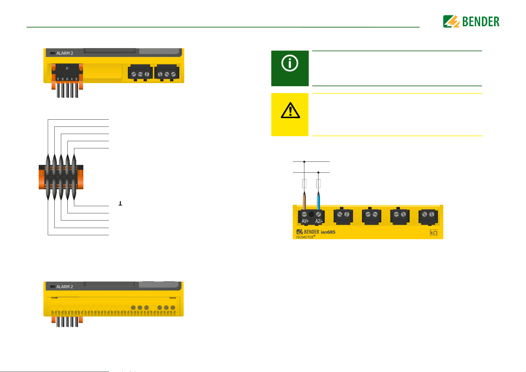
6.4 Connection to the X1 interface
6.5 Connection to the supply voltage
External Power supply for powering the ISOMETER® via terminal X1
must fulfil immunity and emission standards of the required application. For wiring longer than 1 m the use of a shielded cable is
prescribed.
Danger of damage to property due to faulty connections!
The device can be damaged if the unit is simultaneously connected
to the supply voltage via the X1 interface, and A1/+ and A2/- terminals. Do not connect the device simultaneously via X1, and A1/+
and A2/- to different supply voltages.
Position the terminal cover and click it into place
19
isoNAV685-D-B_D00264_03_M_XXEN/06.2017
Page 20

ConnectionConnection
11
12
14
Relay 1
Common contact
Normally open (n.o)
Normally closed (n.c)
6.6 Connection to the Ethernet interface
Position the terminal cover and click it into place
6.7 Connection to the relay 1 interface (11 12 14)
Position the terminal cover and click it into place
20
isoNAV685-D-B_D00264_03_M_XXEN/06.2017
Page 21

6.8 Connection to the relay 2 interface (21 22 24)
21
22
24
Relay 2
Common contact
Normally closed (n.c)
Normally open (n.o)
Position the terminal cover and click it into place
ConnectionConnection
21
isoNAV685-D-B_D00264_03_M_XXEN/06.2017
Page 22

7. Commissioning
Commissioning the ISOMETER®
Adjust basic settings if
necessary
Install the device according to the
wiring diagram
and documentation
Connect the supply voltage
Connect the system voltage
The ISOMETER® performs a self
test
Function test with a suitable
resistance between system and
earth. Resistance value: 50% of
the response value Alarm 2
Remove the resistance
The ISOMETER® is properly
connected and
functions reliably
Run the commissioning
wizard
For further information regarding device settings, refer to chapter “Settings”
from page 29.
Commissioning
7.1 General initial commissioning process
1. Check that the ISOMETER® is properly connected to the system to be monitored.
2. Connect the supply voltage to the ISOMETER®. The ISOMETER® then performs a 4step self test during which the alarm relays are not checked. After completion of the
test, the measured insulation resistance is shown on the display. If the value exceeds
the response values indicated in the lowest line of the display, the message "OK" will
additionally be displayed.
For customer-specific configured devices, the commissioning wizard
might be deactivated and cannot be run. In this case, the device is preset.
However, the commissioning wizard can be started as described at
3. Check the ISOMETER® in the system being monitored, e.g. using a suitable resistance to earth.
7.2 Recommissioning
If the device has already been put into operation before, the self-test will be started shortly after the supply voltage has been connected.
The device settings can also be carried out via the commissioning-wizard, which can be
manually started via the menu path:1
Menu/Device settings/Commissioning
This menu can be used to modify settings made previously.
“Display” on page 23.
Observe device status!
The device is in an alarm state until initial commissioning has been
completed.
Commissioning flow chart
Observe the device status!
The device changes from the alarm state to normal state after
22
completing initial commissioning and initial measurement by adhering to the response values set.
isoNAV685-D-B_D00264_03_M_XXEN/06.2017
Page 23

8. Display
IT System
OK
L1 230 kΩ
L2 250 kΩ
L3 130 kΩ
R(an) 50kΩ
OK
L1 230 kΩ
L2 250 kΩ
L3 130 kΩ
Display
8.1 Standard display
In normal operation, the ISOMETER® displays the message OK and below the latest measured insulation resistance of the connected system points L1, L2 and L3.
The signal quality of the measurement suits the selected profile.
The better the signal quality, the faster and more exact the device can
measure.
The signal quality of the measurement does not suit the selected profile. Select a different measurement profile.
Update period between the test pulses
In the bottom line of the display, the set limit value for R(an) is indicated.
In the example shown below Ran=50 k.
8.2 Fault display (active)
An active fault is displayed by . The upper part of the display will become orange and
displays the fault message.
Depending on the type of fault, the LEDs ALARM 1, ALARM 2 or SERVICE are activated.In
the example below, the insulation resistance is still 23
If several fault messages have appeared, you can navigate through the faults using the
and button.
ALARM
Iso. Alarm L1
23 kΩ
23
5/7
isoNAV685-D-B_D00264_03_M_XXEN/06.2017
Page 24

DisplayDisplay
230 kΩ
IT System
3x
1/4
230 kΩ
Insulation fault
28.03.14 17:0 2
28.03.14 17:18
2/4
7 kΩ7 kΩ
8.3 Fault display (inactive)
An inactive fault is displayed by . If several faults have occurred, the number of faults
will also be indicated.
This message means that there has been a fault in the past but the device is no longer in
fault condition.
If several fault messages occur, you can navigate through the faults using the and
button. In addition to the type of fault and the associated alarm value, you can see when
the fault has occurred and how long it has been active.
24
isoNAV685-D-B_D00264_03_M_XXEN/06.2017
Page 25

DisplayDisplay
RESET 3.2
Reset current
messages? All
messages are
saved in the
history memory.
Cancel RESET
Historie 4.1
Isolationsfehler
11kΩ
28.03.14 17:02
28.03.14 17:18
8/8
Next message
Leave view
Fault description
Alarm value
Feault occured
Fault disappeared
Previous message
Number of selected
errors/
Tot al number of
error messages
8.4 Acknowledge fault memory
In order to acknowledge the fault message and return to the ISOMETER®'s standard
display, all faults must be acknowledged by means of the reset button.
This means that fault messages can only be reset when the cause of the fault has been
eliminated.
Press the reset button, then and OK to clear the fault memory.
The ISOMETER® then returns to the standard display.
8.5 History memory
Up to 1023 alarm messages and device errors are stored in the history memory with date
and t ime stam p. When t he histo ry memory is deleted, the minimum insulation resistance
will also be reset under Menu/ Data Measured values - Data insulation - Reset.
R
min
25
isoNAV685-D-B_D00264_03_M_XXEN/06.2017
Page 26

8.6 Initial measurement
IT System
R(an) 40kΩ/10 kΩ
Initial
measurement
Initial
measurement
During the initial measurement, the device records all measured values.
All measured values that may have been recorded before will be discarded if a new initial
measurement is started.
DisplayDisplay
26
isoNAV685-D-B_D00264_03_M_XXEN/06.2017
Page 27

9. Menu
1. Alarm settings 1. Insulation alarm 1. Alarm 1
2. Voltage
3. t(on)
3. Memory
2. Profile
3. System type
4. Coupling
5. Device
6. t(start)
7. Coupling monitoring
8. Inputs 1. Digital 1 1. Mode
2. t(on)
3. t(off)
4. Function
2. Digital 2 1. Mode
2. t(on)
3. t(off)
4. Function
3. Digital 3 1. Mode
2. t(on)
3. t(off)
4. Function
9. Ausgänge 1. Relais 1 1. Test
2. Relay mode
3. Function 1
4. Function 2
5. Function 3
2. Relais 2 1. Test
2. Relay mode
3. Function 1
4. Function 2
5. Function 3
3. Digital 1 1. Test
2. Relay mode
3. Function 1
4. Function 2
5. Function 3
4. Digital 2 1. Test
2. Relay mode
3. Function 1
4. Function 2
5. Function 3
5. Summer 1. Test
2. Function 1
3. Function 2
4. Function 3
2. Data meas. values
3. Control
4. History
5. Device settings 1. Language
2. Cloc
k
1. Time
2. Format
3. Summer time
4. Date
5. Format
6. NTP
7. NTP Server
8. UTC
3. Interface 1. Write access
2. Ethernet 1. DHCP
2. IP
3. SN
4. Std. GW
5. DNS Server
6. Domäne
3. BCOM 1. System name
2. Subsystem
3. Device address
4. Timeout
5. TTL
4. Modbus TCP 1. Port 502
5. BS-Bus 1. Address
4. Displa
y
1. Brightness
5. Passwort 1. Passwort
2. Status
6. Commissioning
7. Data protection
8. Service
6. Info
9.1 Menu structure
Menu
27
isoNAV685-D-B_D00264_03_M_XXEN/06.2017
Page 28

9.2 Operating and navigating
System type 5.6.6
• 3AC
Date 5.2.4
14.01.2014
min. 1
max. 31
Ethernet 6.3.2
-.0123456789abcdef
ghijklmnopqrstuvwx
yz del
Navigate through the device menu using the device buttons. The functions of the device
buttons are described in the chapter “Display elements and device buttons” on page 14.
9.2.1 Easy operation
Navigation in lists
To make a selection in a list, navigate using
the and buttons to the required
menu item. Then click "OK".
Navigation with arrows
You can increase or decrease a value using
the and buttons. You can move to
the left or the right to set different values
using the and buttons. The value positioned between the symbols is the value that is set.
MenuMenu
Text input
Go step by step through the numbers and
letters indicated on the display by using
the button (forwards) and the button
(backwards). Navigate to the right using
the button to enter the next character.
To delete a character that has been entered, use the and buttons to navigate to the character to be deleted and
then select "del" using the and buttons.
Confirm the entered text with "OK".
28
isoNAV685-D-B_D00264_03_M_XXEN/06.2017
Page 29

10. Settings
t
R
an1
Alarm 1
aktiv
Alarm 1
inaktiv
Δ 25 % + 0,5 kΩ
Settings
10.1 Settings in the device menu
The settings of the ISOMETER® are explained in the order of the device menu.
10.1 (1.0)Alarm settings
The limit values for the insulation resistances of alarm 1 and alarm 2 can be specified in
the alarm settings menu and can be adapted to the user profile of the ISOMETER®.
A device password is required for entering the settings. You can adjust the following
functions:
10.1 (1.1) Insulation alarm
10.1 (1.2) Profile
The ISOMETER® profile is set to "Offline".
System
Measuring
voltage
± 5 V
Offline
leakage
capacitanc
e
µF
150
Description
For disconnected loads and
frequency converters.
In the "Insulation alarm" menu, you can set the limits for the ISOMETER® ALARM:
10.1 (1.3) System type
The activation or deactivation of the alarm for R
is illustrated in the following graph:
an
The device is set to a 3AC system.
An alarm will become inactive as soon as +25 % +0.5 k of the set operating value is
exceeded.
•3AC
3AC system
(refer to “Connection to a 3(N)AC system/system type 3AC”
on page 18)
10.1 (1.4) Device
Set the ISOMETER® insulation resistance measurement function to active or inactive:
•Active
•Inactive
The device is active.
The device DOES NOT measure the insulation resistance, the
message Device inactive appears on the display. The
IT system is NOT being monitored!
10.1 (1.1.1) Alarm 1
For Alarm 1, an insulation resistance of between 1 k…10 M can be set.
10.1 (1.1.2) Fault memory
Automatic reset of inactive faults at the outputs relay 1, relay 2, digital output 1, digital
output 2:
10.1 (1.5) T(Start)
The ISOMETER® can be operated with a start-up delay of 0…120 seconds. The start-up is
delayed until the initial measurement takes place.
10.1 (1.6) Coupling monitoring
Coupling monitoring (L1, L2, L3 network connection monitoring) is deactivated.
•on
•off
If a fault becomes inactive, the programmed outputs remain
in fault condition until they are reset manually.
If a fault becomes inactive, the programmed outputs automatically change the state.
•off
Coupling monitoring is deactivated.
29
isoNAV685-D-B_D00264_03_M_XXEN/06.2017
Page 30

10.1 (1.7) Inputs
I2
I3
A
B
M+
Q2
Q1
+
Device
inactive
Reset Test
I1
+I
x
X1 X1
t
0
1
t(on)
Reaction
Impulse on
Reaction
Impulse o
+I
x
X1 X1
The ISOMETER® provides a total of three digital inputs.
The exemplary wiring diagram shows how the digital inputs can be wired:
SettingsSettings
•Active low
1
An event is carried out on the falling edge of the digital input (high
to low).
Response time t(on)/t(off) after a switch-off signal.
10.1 (1.7.1) Digital 1
The following parameters can be set for the digital input:
10.1 (1.7.1.1) Mode
The operating mode for the digital input can be set to the following values:
•Active high
< t(on)
An event is carried out on the rising edge of the
digital input (low to high).
Response time t(on)/t(off) after a switch-on signal.
Reaction Reaction
0
< t(on)
t(on)
Impulse onImpulse o
t
10.1 (1.7.1.2) t(on)
The response time t(on) after a switch-on signal can be set between 100 milliseconds and
300 seconds (refer to “10.1 (1.7.1.1) Mode”).
10.1 (1.7.1.3) t(off)
The response time t(off) after a switch-off signal can be set between 100 milliseconds and
300 seconds (refer to “10.1 (1.7.1.1) Mode”).
10.1 (1.7.1.4) Function
The parameters for the function of the digital inputs of the ISOMETER® can be set
differently:
•off
•TEST
•RESET
•Deactivate
device
Digital input without function
Device self test
Reset of fault and alarm messages
The device DOES NOT measure the insulation resistance, the message Device inactive appears on the display.
The IT system is NOT being monitored!
30
isoNAV685-D-B_D00264_03_M_XXEN/06.2017
Page 31

SettingsSettings
≥ 1
Response
Function 1
Function 2
Function 3
10.1 (1.7.2) Digital 2
Refer to “10.1 (1.7.1) Digital 1”.
10.1 (1.7.3) Digital 3
Refer to “10.1 (1.7.1) Digital 1”.
10.1 (1.8) Outputs
The ISOMETER® provides a total of six outputs.
The following parameters can be set for the outputs:
10.1 (1.8.1) Relay 1
The following parameters can be set for each relay:
10.1 (1.8.1.1) TEST
The functional test of the relay can be activated or deactivated. This only applies to the
manual test and not to the cyclic device self test:
•on
•off
The manual test checks the switching function of the relay
The manual test does not check the switching function of the relay
10.1 (1.8.1.2) Relay mode
The relay mode can be adapted to the application:
•N/C
Normally closed- N/C operation contacts11-12-14 / 21-22-24
(in fault-free condition, the alarm relay is energised).
Select the appropriate setting for function 1. The following parameters can be set.
•off
•Ins. Alarm 1
•Ins. Alarm 2
•Connection fault
•Device fault
•Device inactive
The function is not used.
The status of the output changes when the value falls below the set
response value R
The status of the output changes when the value falls below the set
response value R
The status of the output changes when one of the following connection fault occurs:
• No low-resistance connection between the line conductors.
• No low-resistance connection between the terminals E and KE to
earth (PE).
• The load connected to the current output is too low
• The load connected to the current output is too high.
• Load on X1 too high.
The status of the output changes in the event of an internal device
fault.
The status of the output changes when the device has been
deactivated via a digital input or the control menu.
an1.
an2.
•N/O
Normally opened - N/O operation contacts
(in fault-free condition, the alarm relay is de-energised).
11-12-14 /
21-22-24
10.1 (1.8.1.3) Function 1
Up to three functions can be assigned to one output. The functions are linked to an OR
operator:
31
isoNAV685-D-B_D00264_03_M_XXEN/06.2017
Page 32

SettingsSettings
X1
iso685
Qx
+
oder
internal
external
10.1 (1.8.1.4) Function 2
Refer to “10.1 (1.8.1.3) Function 1”.
10.1 (1.8.1.5) Function 3
Refer to “10.1 (1.8.1.3) Function 1”.
10.1 (1.8.2) Relay 2
Refer to “10.1 (1.8.1) Relay 1”.
10.1 (1.8.3) Digital 1
The following parameters can be set for each of the digital outputs:
The functional test of the digital output can be activated or deactivated. This only applies
to the manual test and not to the cyclic device self test:
•on
•off
The manual test changes the status of the digital output.
The manual test does not change the status of the digital output.
10.1 (1.8.3.1) Mode
The following settings can be used to set the operating mode for the digital output:
•Active
In the active mode +24 V will be internally applied across the output.
X1
+
Qx
X1
+
Qx
•Passive
iso685
In the passive mode ≤ 32 V are externally connected (see technical
data). The output switches the applied potential to ground.
X1
+
iso685
Qx
iso685
32
Observe the maximum output current!
Maximum output current in case of internal voltage supply
via A1/+ and A2/-: 200 mA in total to X1.
Also refer to the formula for calculating I
der “Digital Outputs (Q1, Q2)” on page 45.
10.1 (1.8.3.2) Function 1
Refer to “10.1 (1.8.1.3) Function 1”.
10.1 (1.8.3.3) Function 2
Refer to “10.1 (1.8.1.3) Function 1”.
10.1 (1.8.3.4) Function 3
Refer to “10.1 (1.8.1.3) Function 1”.
10.1 (1.8.4) Digital 2
in the Technical Data un-
LmaxX1
isoNAV685-D-B_D00264_03_M_XXEN/06.2017
Page 33

SettingsSettings
Refer to “10.1 (1.8.3) Digital 1”.
10.1 (1.8.5) Buzzer
The following parameters can be set for the buzzer:
10.1 (1.8.5.1) TEST
The functional test of the buzzer can be activated or deactivated. This only applies to the
manual test and not to the cyclic device self test:
•on
•off
The manual test activates the buzzer sound.
The manual test does not activate the buzzer sound.
10.1 (1.8.5.2) Function 1
Refer to “10.1 (1.8.1.3) Function 1”.
10.1 (1.8.5.3) Function 2
Refer to “10.1 (1.8.1.3) Function 1”.
10.1 (1.8.5.4) Function 3
Refer to “10.1 (1.8.1.3) Function 1”.
10.1 (2.0) Data measured values
The ISOMETER® stores certain measured values for a specific period of time. You can view
these data at the "Data meas. values" menu point. Navigate through the different views
using the and buttons:
10.1 (4.0) History
In the history menu, the faults detected by the ISOMETER® are displayed. For a detailed
functional description, refer to “History memory” on page 25.
•History
•Delete
Overview of faults that have occurred
Reset the history memory
10.1 (5.0) Device settings
The device settings menu allows you to configure the basic settings for the ISOMETER®.
10.1 (5.1) Language
Choose the language to be displayed by the ISOMETER®. For example, you can set the languages:
•German
•English
10.1 (5.2) Clock
In the clock menu you can set the display format of time and date for the ISOMETER®:
10.1 (5.2.1) Time
Based on the selected time format you can set the current time to display 24-hour or 12hour notation (am/pm).
•Insulation data
Display the insulation resistance of the three coupling paths L1, L2,
L3
10.1 (3.0) Control
In the control menu, you can start a manual test reset, reset alarm messages and start an
initial measurement:
•TEST
•RESET
Manual device test
Reset of fault and alarm messages
33
10.1 (5.2.2) Format (time)
Select the appropriate time format to be displayed:
•12 h
•24 h
12-hour notation am/pm
24-hour notation
isoNAV685-D-B_D00264_03_M_XXEN/06.2017
Page 34

SettingsSettings
10.1 (5.2.3) Summer time
Summer time can be considered in the following settings:
•off
•DST
•CEST
No automatic change between summer time and standard time.
Daylight Saving Time
Automatic change between summer and standard time according to
North American regulation.
North American summer time begins on each second Sunday in
March at 02:00 local time by setting the clock forward by one hour
from 2:00 to 03:00 local time. Summer time always ends the first Sunday in October at 03:00 local time by setting the clock back one hour
from 3:00 to 2:00.
Central European Summer Time
Automatic change between summer time and standard time according to Central European regulation.
Central European summer time begins on each last Sunday in March
at 02:00 CEST by setting the clock forward by one hour from 2:00 to
03:00. Central European summer time always ends on the last Sunday in October at 03:00 CEST by setting the clock back one hour
from 3:00 to 2:00.
When set to DST or CEST, changing between summer time and normal time
is only done on the date of the official time change.
10.1 (5.2.6) NTP
Select if you would like to synchronise the current time via NTP:
•on
•off
Synchronisation via NTP server is activated.
Synchronisation via NTP server is deactivated.
10.1 (5.2.7) NTP server
Set NTP server.
10.1 (5.2.8) UTC
Set the time according to UTC (coordinated world time). For Germany, set +1 for wintertime (MEZ) and +2 for summer time (MESZ).
10.1 (5.3) Interface
Set the parameters for the connection of other devices to the ISOMETER® in the interface
menu:
10.1 (5.3.1) Write access
Set whether the device can be parameterised externally via Modbus or web server. Displaying and reading out data via Modbus and web server is always possible, regardless of
this setting.
•Allow
•Deny
Allow external parameter setting.
Refuse external parameter setting.
10.1 (5.2.4) Date
Based on the selected date format you can set the current date.
10.1 (5.2.5) Format (date)
Select the appropriate date format you want to be displayed:
•dd.mm.yy
•mm-dd-yy
day, month, year
month, day, year
34
10.1 (5.3.2) Ethernet
Set the parameters for communication with other devices via the Ethernet interface. The
Ethernet interface can be used for communication with Modbus, web server and BCOM.
10.1 (5.3.2.1) DHCP
Select whether you want to use automatic address assignment via your DHCP server.
When the automatic IP address assignment is activated, the IP address, subnet mask and
the standard gateway are assigned automatically. When the automatic IP address assignment is deactivated, you have to make these settings manually in the menu.
The IP address can be viewed in the “Info“ menu (see “Info” on page 36).
•on
Activate automatic IP address assignment.
isoNAV685-D-B_D00264_03_M_XXEN/06.2017
Page 35

SettingsSettings
•off
Deactivate automatic IP address assignment.
10.1 (5.3.2.2) IP
Set the appropriate IP address for the ISOMETER®.
10.1 (5.3.2.3) SN
Set the appropriate subnet mask.
10.1 (5.3.2.4) Std. GW
If a standard gateway is used, enter the IP address here.
10.1 (5.3.2.5) DNS server
If a DNS server is used, enter the server's IP address.
Contact your network administrator in case you have questions about the configuration
of the DNS server.
10.1 (5.3.2.6) Domain
Enter the domain.
Contact your network administrator in case you have questions about the configuration
of the domain.
10.1 (5.3.3) BCOM
Set the parameters for communication with other devices via BCOM.
For further information, refer to “BCOM” on page 37.
10.1 (5.3.3.1) System name
Set the system name of the network in which the devices are located. In order to guarantee that all devices are able to communicate via BCOM, all devices must have the same
system name.
10.1 (5.3.3.2) Subsystem
Configure the subsystem address of the network in which the devices are located. The devices can communicate with subsystems with the same or different subsystem addresses.
10.1 (5.3.3.3) Device address
Assign a device address. Each device must have a different address to distinguish it from
another in the system and ensure correct communication.
10.1 (5.3.3.4) Timeout
Set the timeout for messages between 100 ms…10 s.
This time specification defines the maximum permissible time for a device to respond.
10.1 (5.3.3.5) TTL for subscription
Set a time between 1 s…1092 min.
This time defines the intervals at which the ISOMETER® sends messages to e.g. a gateway.
Severe alarms (e.g. insulation alarms or substantial value changes) are always sent immediately.
10.1 (5.3.4) Modbus TCP
Settings for communication with other devices via Modbus TCP.
For further information, refer to “Modbus TCP” on page 37.
10.1 (5.3.4.1) Port 502
Choose whether Modbus TCP should be used:
•on
•off
Modbus TCP can be used for communication with other devices.
Modbus TCP cannot be used for communication with other devices.
10.1 (5.3.5) BMS bus
The function of the BMS bus is not available in this device.
10.1 (5.4) Display
Adjust the display brightness for the ISOMETER® in the display menu:
10.1 (5.4.1) Brightness
Adjust the display brightness between 0 % and 100 % in steps of 10.
If no button is pressed on the display for 15 minutes, the brightness of the display is reduced. If now a button is pressed, the normal brightness is restored.
10.1 (5.5) Password
Use the password function to protect the device parameters against unauthorised adjustment. The default password is 0000.
10.1 (5.5.1) Password
Enter an individual four-digit password.
35
isoNAV685-D-B_D00264_03_M_XXEN/06.2017
Page 36

10.1 (5.5.2) Status
Decide if the password query should be used:
SettingsSettings
•on
•off
Password query active
Password query inactive
10.1 (5.6) Commissioning
In the commissioning menu you can open the ISOMETER®'s commissioning wizard again.
10.1 (5.7) Data backup
In the data backup menu device settings can be saved or device settings already saved
can be restored.
•Save
•Restore
The ISOMETER® saves your device settings.
The ISOMETER® restores your initial device settings.
10.1 (5.8) Service
The service menu can only be accessed by Bender Service staff.
10.1 (6.0) Info
The ISOMETER®'s current settings can be viewed in the Info menu. Navigate through the
different views using the and buttons:
•Device
•Software
Device name, serial number, article number
Software version measurement technique,
software version HMI
•Measurement
-technique
•Clock
•Ethernet
•BMS bus
36
Selected profile, selected system type
Time, date, summer time
IP address, DHCP status, MAC address
No function
isoNAV685-D-B_D00264_03_M_XXEN/06.2017
Page 37

11. Device communication
Device communication
11.1 Ethernet interface
The Ethernet interface can be used for communication with Modbus, web server and
BCOM.
11.2 BCOM
BCOM is intended for communication between Bender devices via Ethernet.
All devices that communicate via BCOM must have the same system name. Devices can
be organised in subsystems. Each device requires an individual device address.
For more information regarding BCOM, refer to the BCOM manual (D00256)
at http://www.bender.de/manuals.
When address 0 has been set for communication via BCOM the device can
be accessed via the network (e.g. for parameter setting, etc.) but it cannot
communicate with other devices.
11.3 Modbus TCP
Modbus is an international widely used protocol for data transfer between devices.
All measured values, messages and parameters are stored in virtual register addresses.
Data can be read out with a read command on the register address. With a write command, data can be written into a register address.
The register addresses of the individual measured values und parameters can be found
in the manual "iso685-D Annex A" with the title "ISOMETER® iso685 device family - Modbus settings" at http://www.bender.de/manuals.
A maximum of 5 TCP/IP connections can be used simultaneously.
In order to be able to parameterise the device externally via Modbus, the
menu item "Allow" must have been set in the "Write access" menu (see
“Write access” on page 34).
37
isoNAV685-D-B_D00264_03_M_XXEN/06.2017
Page 38

Device communicationDevice communication
1
2
3
4
11.4 Web server
The ISOMETER® has an integrated web server which displays ISOMETER® data comfortably on every PC via a web browser. The web server can be used to read out measured values and parameterise the ISOMETER®s. You can access the web server by entering the IP
address of the ISOMETER® into the browser (e.g. http://192.168.0.5). The Info menu provides information about the ISOMETER®‘s IP address (see 10.1 (6.0) “Info” on page 36).
The web server offers the following functions:
• Visualisation
• Indication of device information (e.g. device type, software version, etc.)
• Indication of current device settings.
• Indication of alarm messages.
• Indication of the Modbus information of the individual parameters.
• Indication of the interfaces in use.
• Overview of the current measured values.
• Detailed graphic representation of the insulation resistance (isoGraph).
• Fast and simple visualisation without any programming.
• Parameter setting
• Easy and fast parameter setting of the device.
• Easy assignment and edition options of device and measuring channel texts.
• Maintenance
• Data storage of specific events for fast support by Bender Service.
A maximum of 5 TCP/IP connections can be used simultaneously.
The write access is deactivated by default in the device menu (= Deny). To
be able to set parameters via the web server the write access must first be
activated in the device menu (= Allow) (see “Write access” on page 34).
Use the web server preferably with the following web browsers:
Google Chrome, Mozilla Firefox or Internet Explorer.
Web server device menu (first level)
Legend for web server device menu (first level)
1 START Indication of general device information.
2DEVICE
3 ALARMS Indication of alarm messages.
4
PARAMETER
ADDRESSES
Indication of an overview of alarm values and measured values.
Indication of the settings. Settings can be changed here.
Activate and deactivate the indication of the Modbus information by
selecting or deselecting the selection box for the question "Display
additional Modbus information for each parameter?".
38
Only one device may access the web server at the same time. If several devices try to access the web server it may result in timeouts.
isoNAV685-D-B_D00264_03_M_XXEN/06.2017
Page 39
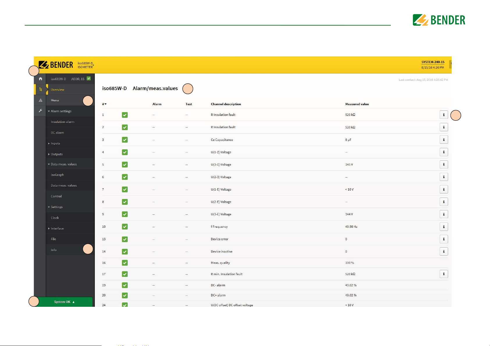
Device communication
Web server user interface
5
9
6
10
39
7
8
isoNAV685-D-B_D00264_03_M_XXEN/06.2017
Page 40

Legend for user interface
Main menu of the web server (first level)
•START (1)
5
6 Menu Adjust device settings here.
7Info
8
9
System OK/
alarms
Alarm/
meas.values
•DEVICE (2)
• ALARMS (3)
• PARAMETER ADDRESSES (4)
Refer to “Web server device menu (first level)” on page 38.
• Indication of device information regarding software, measurement
technique and Ethernet address.
• Indication of Modbus information for the individual parameters.
To be able to see this information, the selection box at PARAMETER
ADDRESSES (4) for the question "Display additional Modbus information for each parameter?" must be activated.
Indication of the system status "System OK" (green button) and "Alarms"
(red button).
If there are pending alarms, click on the red button or go to menu point
"ALARMS" (3) to obtain further information.
Overview of alarm values and measured values.
Device communicationDevice communication
10 i symbol
40
Click on the "i" symbol on the right side to obtain further information
regarding measured values.
isoNAV685-D-B_D00264_03_M_XXEN/06.2017
Page 41

12. Diagrams
Ce ≤ 150 µF
C
e
≤ 50 µF
C
e
≤ 20 µF
Ce ≤ 5 µF
Ce ≤ 1 µF
10
100
1000
100010010
Response time as a function of the response value (Ran) and system leakage
capacitance (C
e
) according to IEC 61557-8 (Un = AC 690 V, fn = 60 Hz)
Response time [sec]
Response value R
an
[kΩ]
0%
10%
20%
30%
40%
50%
60%
70%
80%
90%
100%
0000010000100010010111,0
Operating uncertainty [%]
C
e
<=150μF
C
e
<=1μF
Relative uncertainty as a function of the response value (Ran) and system leakage
capacitance (Ce) according to IEC 61557-8 (Un = AC 690 V, fn = 60 Hz)
12.1 Response time profile offline
12.2 Relative uncertainty
41
isoNAV685-D-B_D00264_03_M_XXEN/06.2017
Page 42

13. Alarm messages
Alarm message Description Measures Reference LED indicators
Check E-KE connections
for interruptions!
Service mode active! The device is in maintenance condition • Contact Bender Service SERVICE lights up
No DHCP server found! Connection problem at the Ethernet interface
Check time and date! Time and date have not been set yet
Load on X1 too high! Sum of the external loads on X1 is too high
Device error x.xx Internal device fault
No low-resistance connection between terminals E and
KE to earth (PE)
• Check the wiring of terminals E and KE to earth (PE)
• Press the test button
• Check cable connection at the Ethernet interface
• Check the DHCP server's availability
• Check the DHCP's interface configuration in the device
• Set local time and date
(in case of voltage failure a buffer for three days)
• Check load at X1.+, X1.Q1 and X1.Q2
• Check ambient temperature
• Press the TEST button
• Switch the supply voltage off and on
•Contact Bender Service
“Connection” on
page 16
“DHCP” on page 34
“Clock” on page 33
ALARM 1 + ALARM
2 flash in common
mode
SERVICE lights up
42
isoNAV685-D-B_D00264_03_M_XXEN/06.2017
Page 43

14. Factory settings
Factory settings
Parameter Value
Response values/alarms
Response value R
Response value R
DC alarm off
DC-offset voltage for DC alarm 65 V
Fault memory off
Coupling monitoring on
Time response
Start-up delay T
Digital inputs
Digital input 1
Mode (Operating mode) Active high
Function TEST
Digital input 2
Mode (Operating mode) Active low
Function RESET
Digital input 3
Mode (Operating mode) Active high
Function Deactivate device
an1
an2
start-up
(ALARM 1)
(ALARM 2)
40 k
10 k
0 s
Parameter Value
Function 3 off
Switching elements
Relay 1
Tes t o n
Operating mode N/C operation
Function 1 Ins. alarm 1
Function 2 Connection fault
Function 3 off
Relay 2
Tes t o n
Operating mode N/C operation
Function 1 Ins. alarm 2
Function 2 Device fault
Function 3 Connection fault
Interfaces
DHCP off
IP address 192.168.0.5
Net mask 255.255.255.0
BCOM address system-1-0
Digital outputs
Digital output 1
Function 1 off
Function 2 off
Function 3 off
Digital output 2
Function 1 off
Function 2 off
43
System
System type 3AC
Profile Power circuits
isoNAV685-D-B_D00264_03_M_XXEN/06.2017
Page 44

15. Technical data
Technical data
15.1 Tabular data
Insulation coordination according to IEC 60664-1/IEC 60664-3
Definitions:
Measuring circuit (IC1).............................................................................................................................................(L1/+, L2, L3/-)
Supply circuit (IC2)................................................................................................................................................................... A1, A2
Output circuit 1 (IC3)...........................................................................................................................................................11, 12, 14
Output circuit 2 (IC4)...........................................................................................................................................................21, 22, 24
Control circuit (IC5) .................................................................................................................................... (E, KE), (X1, ETH, X3, X4)
Rated voltage....................................................................................................................................................................................1000 V
Overvoltage category ............................................................................................................................................................................... III
Rated impulse voltage:
IC1 / (IC2-5) ................................................................................................................................................................................. 8 kV
IC2 / (IC3-5) ................................................................................................................................................................................. 4 kV
IC3 / (IC4-5) ................................................................................................................................................................................. 4 kV
IC4 / IC5 ........................................................................................................................................................................................ 4 kV
Rated insulation voltage:
IC1 / (IC2-5) .............................................................................................................................................................................1000 V
IC2 / (IC3-5) ...............................................................................................................................................................................250 V
IC3 / (IC4-5) ...............................................................................................................................................................................250 V
IC4 / IC5 ......................................................................................................................................................................................250 V
Pollution degree for accessible parts on the outside of the device housing (U
Pollution degree for accessible parts on the outside of the device housing (U
Protective separation (reinforced insulation) between:
IC1 / (IC2-5) ....................................................................................................................................Overvoltage category III, 1000 V
IC2 / (IC3-5) ......................................................................................................................................Overvoltage category III, 300 V
IC3 / (IC4-5) .......................................................................................................................................Overvoltage categoryIII, 300 V
IC4 / IC5 ............................................................................................................................................. Overvoltage category III, 300 V
Voltage test (routine test) according to IEC 61010-1:
IC2 / (IC3-5) ........................................................................................................................................................................ AC 2,2 kV
IC3 / (IC4-5) ........................................................................................................................................................................ AC 2,2 kV
IC4 / IC5 ............................................................................................................................................................................... AC 2,2 kV
Supply voltage
Supply via A1/+, A2/-:
Supply voltage range U
Tolerance of U
Maximum permissible input current of U
Frequency range of U
...............................................................................................................................................AC/DC 24…240 V
s
..................................................................................................................................................................... -30…+15 %
s
................................................................................................................................................. DC, 50…400 Hz
s
.................................................................................................................................... 650 mA
s
Tolerance of the frequency range of Us................................................................................................................................. -5…+15 %
Power consumption, DC................................................................................................................................................................ ≤ 12 W
Power consumption, typically 50/60 Hz .......................................................................................................................... ≤ 12 W/21 VA
< 690 V)..................................................................... 3
n
>690 < 1000 V)........................................................ 2
n
Power consumption, typically 400 Hz ............................................................................................................................. ≤ 12 W/45 VA
Supply via X1:
Supply voltage U
Tolerance of U
............................................................................................................................................................................ DC 24 V
s
............................................................................................................................................................... DC -20…+25 %
s
IT system being monitored
Nominal system voltage range Un....................................................................................................................................................offline
Circuit capacity internal mains switch ......................................................................................................AC 0…690 V; DC 0…1000 V
...................................................................................................................................................... AC/DC 0…600 V (for UL applications)
Response values
Response value R
Response value R
(alarm 1) ...........................................................................................................................................1 kΩ…10 MΩ
an1
(alarm 2) ...........................................................................................................................................1 kΩ…10 MΩ
an2
Relative uncertainty (acc. to IEC 61557-8) ............................................................................profile dependent, ±15 %, at least ±1 kΩ
Hysteresis ...................................................................................................................................................................... 25 %, at least 1 kΩ
Time response
Response time t
Start-up delay T
at RF = 0.5 x Ran (Ran = 10 kΩ) and Ce = 1 μF according to IEC 61557-8.......................................................... 30 s
an
............................................................................................................................................................... 0…120 s
start-up
Measuring circuit
Measuring voltage U
Measuring current I
Internal resistance R
Permissible extraneous DC voltage U
Permissible system leakage capacitance C
Display
Indication .......................................................................................................................graphic display 127 x 127 pixels, 40 x 40 mm
........................................................................................................................................................................ ±5 V
m
..................................................................................................................................................................≤ 13,4 μA
m
,Zi............................................................................................................................................................... ≥ 372 kΩ
i
.......................................................................................................................................≤ 1200 V
fg
.....................................................................................................................................150 μF
e
2)
Display range measured value ........................................................................................................................................ 0.1 kΩ…20 MΩ
LEDs
ON (operation LED)............................................................................................................................................................................ green
SERVICE ............................................................................................................................................................................................. yellow
ALARM 1 (L1 and L2) .......................................................................................................................................................................yellow
ALARM 2 (L3) ...................................................................................................................................................................................yellow
In-/Outputs (X1-Interface)
Cable length X1 (unshielded cable)............................................................................................................................................... ≤ 10 m
Cable length X1 (shielded cable, shield connected to earth (PE) on one end, recommended: J-Y(St)Y min. 2x0,8).............. ≤ 100 m
Total max. supply output current via X1.+/X1.GND for each output......................................................................................... max. 1 A
1)
Total max. supply output current via A1/A2 on X1.............................................................................................................. max. 200 mA
Total max. supply output current via A1/A2 on X1 between 16,8 V and 40 V .........................................................................................
.............................................................................................................................................................. I
.............................................................................................................................................(negative values are not allowed for I
= 10mA + 7mA/V * Us
LmaxX1
LmaxX1
3)
)
44
isoNAV685-D-B_D00264_03_M_XXEN/06.2017
Page 45

Technical dataTechnical data
Digital Inputs (I1, I2, I3)
Number ...................................................................................................................................................................................................... 3
Operating mode, adjustable................................................................................................................................... active high, active low
Functions .......................................................................................................................................... none, test, reset, device deactivated
Voltage:..........................................................................................................................................Low DC -3…5 V, High DC 11…32 V
Tolerance Voltage...........................................................................................................................................................................± 10 %
Digital Outputs (Q1, Q2)
Number ...................................................................................................................................................................................................... 2
Operating mode, adjustable................................................................................................................................................. active, passive
Functions ................................................................ off, connection fault, Alarm L1, Alarm L2, Alarm L3, device fault, common alarm
Voltage............................................................................................................................. passive DC 0…32 V, active DC 0/19.2…32 V
Interfaces
Field bus:
Interface/protocol.................................................................................................................................... web server/Modbus TCP/BCOM
Data rate........................................................................................................................................................... 10/100 Mbit/s, autodetect
Max. amount Modbus requests .................................................................................................................................................... < 100/s
Cable length ................................................................................................................................................................................. ≤ 100 m
Connection........................................................................................................................................................................................... RJ45
IP address.........................................................................................................................................................DHCP/manual 192.168.0.5
Network mask..................................................................................................................................................................... 255.255.255.0
BCOM address........................................................................................................................................................................... system-1-0
Function .............................................................................................................................................................. communication interface
Switching elements
Number of switching elements.............................................................................................................................. 2 changeover contacts
Operating mode.......................................................................................................................................... N/C operation/N/O operation
Contact 11-12-14 ................................................... off, connection fault, Alarm L1, Alarm L2, Alarm L3, device fault, common alarm
Contact 21-22-24 ................................................... off, connection fault, Alarm L1, Alarm L2, Alarm L3, device fault, common alarm
Electrical endurance under rated operating conditions, number of cycles ....................................................................................10.000
Contact data acc. to IEC 60947-5-1:
Utilisation category....................................................................................................................AC-13 / AC-14 / DC-12 / DC-12 / DC-12
Rated operational voltage .............................................................................................................. 230 V / 230 V / 24 V / 110 V / 220 V
Rated operational current ............................................................................................................................5 A / 3 A / 1 A / 0.2 A / 0.1 A
Rated insulation voltage ≤ 2000 m NN ...........................................................................................................................................250 V
Rated insulation voltage ≤ 3000 m NN ...........................................................................................................................................160 V
Minimum contact rating ........................................................................................................
.............................. 1 mA at AC/DC ≥ 10 V
ronment/EMC
Envi
................................................................................................................................................................................. IEC 61326-2-4
EMC
Ambient temperatures:
Operating temperature........................................................................................................................................................ -25…+55 °C
Transport ..............................................................................................................................................................................-40…+85 °C
Long-term storage...............................................................................................................................................................-40…+70 °C
Classification of climatic conditions acc. to IEC 60721:
Stationary use (IEC 60721-3-3) ....................................................................................3K5 (except condensation and formation of ice)
Transport (IEC 60721-3-2) ................................................................................................................. ............................................ ..... 2K3
Long-term storage (IEC 60721-3-1)..................................................................................................................... ............................... 1K4
Classification of mechanical conditions acc. to IEC 60721:
Stationary use (IEC 60721-3-3) .......................................................................................................................................................... 3M4
Transport (IEC 60721-3-2).................................................................................................................................................................. 2M2
Long-term storage (IEC 60721-3-1)................................................................................................................................................... 1M3
Area of application................................................................................................................................................................ ≤ 3000 m NN
Connection
Connection type...................................................................................................pluggable screw-type terminal or push-wire terminal
Screw-type terminals:
Nominal current............................................................................................................................................................................... ≤ 10 A
Tightening torque .......................................................................................................................................... 0.5…0.6 Nm (5…7 lb-in)
Conductor sizes ........................................................................................................................................................................ AWG 24-12
Stripping length................................................................................................................................................................................. 7 mm
rigid/flexible........................................................................................................................................................................0.2…2.5 mm²
flexible with ferrules, with/without plastic sleeve ......................................................................................................... 0.25…2.5 mm²
Multiple conductor, rigid.......................................................................................................................................................0.2…1 mm²
Multiple conductor, flexible ...............................................................................................................................................0.2…1.5 mm²
Multiple conductor, flexible with ferrule without plastic sleeve........................................................................................0.25…1 mm²
Multiple conductor, flexible with TWIN ferrule with plastic sleeve ..................................................................................0.5…1.5 mm²
Push-wire terminals:
Nominal current............................................................................................................................................................................... ≤ 10 A
Conductor sizes ........................................................................................................................................................................ AWG 24-12
Stripping length............................................................................................................................................................................... 10 mm
rigid/flexible........................................................................................................................................................................0.2…2.5 mm²
flexible with ferrules, with/without plastic sleeve ............................................................................
f
Multiple conductor,
lexible with TWIN ferrule with plastic sleeve ..................................................................................0.5…1.5 mm²
............................. 0.25…2.5 mm²
4)
45
isoNAV685-D-B_D00264_03_M_XXEN/06.2017
Page 46

Technical dataTechnical data
Push-wire terminals X1:
Nominal current................................................................................................................................................................................. ≤ 8 A
Conductor sizes.........................................................................................................................................................................AWG 24-16
Stripping length............................................................................................................................................................................... 10 mm
rigid/flexible ....................................................................................................................................................................... 0.2…1.5 mm²
flexible with ferrule without plastic sleeve......................................................................................................................0.25…1.5 mm²
flexible with TWIN ferrule with plastic sleeve ...............................................................................................................0.25…0.75 mm²
Other
Operating mode........................................................................................................................................................ continuous operation
Mounting (0°) ......................................................................................... display oriented, cooling slots must be ventilated vertically
Degree of protection internal components ......................................................................................................................................... IP40
Degree of protection terminals ........................................................................................................................................................... IP20
DIN rail mounting acc. to.............................................................................................................................................................IEC 60715
Screw fixing ..................................................................................................................................................... 3 x M4 with mounting clip
Enclosure material................................................................................................................................................................polycarbonate
Flammability class................................................................................................................................................................................. V-0
ANSI code ............................................................................................................................................................................................... 64
Dimensions (W x H x D) .............................................................................................................................................. 108 x 93 x 110 mm
Weight ........................................................................................................................................................................................... < 390 g
1)
At a frequency > 200 Hz, the connection of X1 must be insulated. Only permanently installed devices which at least have over-
voltage category CAT2 (300V) may be connected.
2)
Indication limited outside the temperature range -25…+55 °C.
3)
Us [Volt] = supply voltage ISOMETER®
4)
This is a class A product. In a domestic environment, this product may cause radio interference. In this case, the user may be
required to take corrective actions.
5) Recommendation: Devices mounted at 0 ° (display-oriented, cooling slots must be ventilated vertically).
For devices mounted at an angle of 45°, the max. working temperature is reduced by 10 °C.
For devices mounted at an angle of 90°, the max. working temperature is reduced by 20 °C.
15.2 Standards and certifications
The ISOMETER® has been developed in compliance with the following standards:
• DIN EN 61557-8 (VDE 0413-8):2015-12
• IEC 61557-8:2014-12
• IEC 61557-8:2014/COR1:2016
• DIN EN 61557-8 Ber 1 (VDE 0413-8 Ber 1):2016-12
5)
46
isoNAV685-D-B_D00264_03_M_XXEN/06.2017
Page 47

15.3 Ordering details
Technical dataTechnical data
Typ e
isoNAV685-D-B AC 100…240 V; 47…460 Hz B91067024
Supply voltage U
S
Art. No.
Accessories
Description Art. No.
iso685 Mechanical accessories comprising:
Terminal cover and 2 mounting clips*
iso685 Plug kit, screw terminals* B91067901
iso685 plug kit, with push-wire terminals B91067902
B91067903
Suitable system components
Description Type Art. No.
Suitable measuring instruments
**
: 28 kΩ,120 kΩ
SKMP
Current values: 0…400 A, 0…20 mA
(additonal information here)
7204-1421 B986763
9604-1421 B986764
9620-1421 B986841
**
SKMP = midscale point
47
isoNAV685-D-B_D00264_03_M_XXEN/06.2017
Page 48

16. Glossary
• BCOM Protocol for communication between Bender devices via an IP-based network.
• DHCP Dynamic Host Configuration Protocol. It is used to assign the network configuration to Clients via a server.
• Modbus TCP Modbus is an international widely spread protocol for data transfer.
• System (BCOM)
• Subsystem (BCOM)
• Web server A web server presents the device functions graphically. The web server can be used for reading out measured values and for parameter setting.
The system is the entire installation that is visible for the customer and defined by the customer. The BCOM communication takes place within this
system. Naturally, different systems can exist independently in one network.
The subsystem structures parts of the system as units defined by the customer, e.g. all PQ devices. A typical subsystem are also "non BCOM-capable" devices that are hidden behind a proxy.
48
isoNAV685-D-B_D00264_03_M_XXEN/06.2017
Page 49

17. Modbus settings
Modbus settings
17.1 General information
This appendix provides a complete description of the Modbus register (protocol version 6.0)
for the ISOMETER® iso685 family of devices to facilitate access to information.
The adjustable parameters for individual keys are listed.
In general, the Registers are implemented as Modbus read-only register (RO = read only).
An exception is the DO control register, which only has a write function (WO = write only).
The ISOMETER® iso685 device family supports 4-digit addressing and the following Modbus functions:
4. Holding registers for reading values
(Read Holding Register; function code 0x03)
5. Registers for device programming
(Preset Multiple Registers; function code 0x10)
For the complete Modbus protocol specification, visit
http://www.modbus.org.
17.2 Data access by means of Modbus/TCP-Protokoll
Requests to the iso685 Modbus/TCP-Server are carried out using the Function code FC4
(read input registers). The server generates a function-related response and sends it to
the Modbus client.
Maximum of Modbus TCP requests per second: 100/s.
17.2.1 Exception code
If a request cannot be answered for whatever reason, the server sends a so-called exception code to limit possible errors.
Exception-Code Description
0x01 Invalid function
0x02 Invalid data access
0x03 Invalid data value
0x04 Slave device error
0x05 Acceptance confirmed (response is delayed)
0x06 Request not accepted (repeat request if necessary)
0x08 Memory: Parity error
0x0A Gateway path not available
0x0B Gateway Error
17.2.2 Modbus request
By means of the function code FC3, the required information, in Words, can be read from
the ISOMETER® iso685 input registers. To enable this, the start address and the number of
registers to be read must be specified.
Example:
The insulation value should be read from the input register with a start address of 0x2000.
49
Byte Name Example
Byte 0,1 Transaction identifier 0x0000
Byte 2,3 Protocol identifier 0x0000
Byte 4,5 Length field 0x0006
Byte 6 Unit identifier BCOM device address
Byte 7 Modbus function code 0x03
Register address defined in “Mod-
Byte 8,9
Byte 10,11 Number of Words 0x0002
bus register assignment” on page 520x2000
isoNAV685-D-B_D00264_03_M_XXEN/06.2017
Page 50

Modbus settingsModbus settings
17.2.3 Modbus response
The response consists of 2 bytes per register. The byte sequence is defined with the Most
Significant Bit (MSB) first.
Byte Name Example
…… …
Byte 7 Modbus function code 0x03
Byte 8 Byte count 0x04
Byte 9,10 Value in Register 0 0x1234 (fictitous value)
Byte 11,12 Value in Register 1 0x2345 (fictitous value)
17.2.4 Structure of exception code
Byte Name Example
…… …
Byte 7 Modbus function code 0x83
Byte 8 Exception code 0x01 or 0x02
17.3 Measuring value information
17.3.1 High-byte test status
Value D escr ipti on
0No test
1 Internal test
2External test
17.3.2 Low-byte alarm status
Value D escr ipti on
0 No alarm
1 Pre-warning
2Fault
3 Reserved
4 Warning
5Alarm
17.3.3 High-byte range
Value D escr ipti on
0=
1<
2>
3Invalid
50
isoNAV685-D-B_D00264_03_M_XXEN/06.2017
Page 51

Modbus settings
17.3.4 Low-byte unit
Value D escr ipti on
0Invalid
1None
2Ohm
3Ampere
4Volt
5Percent
6Hertz
7Baud
8 Farad
9Henry
10 Degree Celsius
11 Degree Fahrenheit
12 Second
13 Minute
14 Hour
15 Day
16 Month
17 Watt
18 var
19 VA
20 Wh
21 varh
22 Vah
23 Degree
24 Hertz per second
51
isoNAV685-D-B_D00264_03_M_XXEN/06.2017
Page 52

Modbus settings
17.4 Modbus register assignment
Register address
(hexadecimal)
Device information
0x510 1296 Device model 32 String UTF 8 RO
0x520 1312 Article number 32 String UTF 8 RO
0x530 1328 Serial number 32 String UTF 8 RO
0x540 1344 Manufacturer 96 String UTF 8 RO
0x570 1392 D-number Interface 2 Uint16 RO
0x571 1393
0x578 1400
0x579 1401
Measuring values
0x1010 4112 Channel number (1)
0x1011 4113 Insulation value 4 Float RO Insulation value
0x1013 4115 Test and alarm status 2 Uint16 RO
0x1014 4116 Range and unit 2 Uint16 RO
0x1015 - 0x1018 4117 - 4120 Internal use RO
0x1019 - 0x101F 4121-4127 0 2 Uint16 RO
0x1020 4128 Channel number (2) 2 Uint16 RO
0x1021 4129 Insulation value 4 Float RO Insulation value
0x1022 - 0x102F 4131-4143 See previous channel RO
Register
address
(decimal)
Description
Software-Version
interface
D-number measuring
technique
Software version
measuring technique
Number
2Uint16RO
2Uint16RO
2Uint16RO
number
Data type Mode Comment
Uint16 RO
Range Unit
Software number of the
interface unit
Software number of the
measuring technique
High-byte test, Low-byte alarm status (see
page 50)
High-byte range, Low-byte unit (see
page 50)
Must be read.
Values are only relevant for
internal use.
52
isoNAV685-D-B_D00264_03_M_XXEN/06.2017
Page 53

Modbus settings
Register address
(hexadecimal)
0x1030 4144 Channel number (3) 2 Uint16 RO
0x1031 4145 Leakage capacitance 4 Float RO F
0x1033 - 0x103F 4147-4159 See previous channel RO
0x1040 4160 Channel number (4) 2 Uint16 RO
0x1041 4161 System connection 4 Float RO
0x1043 - 0x104F 4163-4175 See previous channel RO
0x1050 4176 Channel number (4) 2 Uint16 RO
0x1051 4177 Connection to earth 4 Float RO
0x1053 - 0x105F 4179-4191 See previous channel RO
0x1060 4192 Channel number (5) 2 Uint16 RO
0x1061 4193 Device error 4 Float RO
0x1063 - 0x106F 4195-4207 See previous channel RO
Register
address
(decimal)
Description
Number
Data type Mode Comment
0 = O.K.
101 = Error
0 = O.K.
101 = Error
Device error number
(e.g. 750 -> 7.50 Communication CAN)
Range Unit
V
V
V
53
isoNAV685-D-B_D00264_03_M_XXEN/06.2017
Page 54

Modbus settings
Register address
(hexadecimal)
//ReadOnly
0x2000u 8192 Insulation vaue 1 4 Float RO
0x2002u 8194 Insulation vaue 2 4 Float RO
0x2004u 8196 Insulation vaue 3 4 Float RO
0x2018 8216 System connection 4 Float RO
0x201A 8218 Connection to earth 4 Float RO
0x201C 8220 Device error 4 Float RO
0x202A 8234
0x2FFEu 12286 Actual IP Address 4 UInt32 RO
//IP-Configuration
0x3000u 12288 DHCP on/off 2 Uint16 R/W
0x3001u 12289 IP Address 4 Uint32 R/W
0x3003u 12291 Standard Gateway 4 Uint32 R/W
Register
address
(decimal)
Description
Duration of measuring
pulse
Number
4Float RO
Data type Mode Comment
0 = O.K.
101 = Error
0 = O.K.
101 = Error
Device error number
(e.g. 750 -> 7.50 Communication CAN)
0 % = Measuring pulse has switched
100 % = Measuring pulse just before switching
Currently used IP address
aaa.bbb.ccc.ddd => aaa*256³
+ bbb*256²+ ccc*256 + ddd
1 = DHCP on
2 = DHCP off
Configured IP address (used when DHCP =
off)
aaa.bbb.ccc.ddd =>
aaa*256³+ bbb*256² +
ccc*256 + ddd
Configured gateway (used when DHCP =
off)
aaa.bbb.ccc.ddd =>
aaa*256³+ bbb*256² +
ccc*256 + ddd
Range Unit
1…2
0…
4.294.967.295
0…
4.294.967.295
%
%
54
isoNAV685-D-B_D00264_03_M_XXEN/06.2017
Page 55

Modbus settings
Register address
(hexadecimal)
0x3005u 12293 Subnet mask 2 Uint16 R/W
//ModbusTCP Mode
0x3006u 12294 Modbus TCP on/off 2 Uint16 R/W
0x3007u 12295
//ISOnet
0x3008u 12296 ISOnet 2 Uint16 R/W
0x3009u 12297
Register
address
(decimal)
Description
Writing to registers
on/off
Number of isoNet
subscribers via BCOM
Number
2Uint16R/W
2Uint16R/W 2…5
Data type Mode Comment
Configured subnet mask (used when DHCP
= off)
Number of leading “1“ s in the binary subnet mask
e.g. 6 =>
11111100.00000000.0000000
0.00000000 = 252.0.0.0
1 = Port 502 (ModbusTCP) on
2 = Port 502 (ModbusTCP) off
1 = Writing parameters on
2= Writing parameters off
1 = off
2 = ISOnet via BCOM
Range Unit
1…32
1…2
1…2
1…2
//BCOM
0x300Au 12298 BCOM system name 16 String UTF 8 R/W BCOM system name A-Z0-9_
0x3012u 12306
0x3013u 12307 Device address 4 Float R/W 1…255
0x3014u 12308 Message timeout 4 Float R/W BCOM message timeout 0.1…10 s
0x3016u 12310 Repeat interval 2 Uint16 R/W
0x3019u 12313 DNS server IP 4 Uint32 R/W
0x301Bu 12315 DNS domain 250 String UTF 8 R/W DNS domain a-z0-9\.\-
55
BCOM subsystem
address
2 Uint16 R/W BCOM device address 1…255
Time interval in which a BCOM messages is
sent from a device to the Gateway at the
latest
IP address of the DNS server
aaa.bbb.ccc.ddd => aaa*256³
+ bbb*256² + ccc*256 + ddd
0…65.535 s
0…
4.294.967.295
isoNAV685-D-B_D00264_03_M_XXEN/06.2017
Page 56

Modbus settings
Register address
(hexadecimal)
//Time
0x3098u 12440 Time 4 Unix Time R/W
0x309Au 12442 0 4 0 R
0x309Cu 12444 Time zone 4 Float R/W Time zone offset -12…13 h
0x309Eu 12446 NTP on/off 2 Uint16 R/W
0x309Fu 12447 NTP server IP 4 Uint32 R/W
0x30A1u 12449 Date format 2 Uint16 R/W
0x30A2u 12450 Summertime 2 Uint16 R/W
0x30A3u 12451 Time format 2 Uint16 R/W
//BMS
0x30A4u 12452 BMS address 2 Uint16 R/W BMS address 1…90
Register
address
(decimal)
Description
Number
Data type Mode Comment
1 = NTP on
0 = NTP 0ff
IP address of the NTP server
aaa.bbb.ccc.ddd => aaa*256³
+ bbb*256² + ccc*256 + ddd
1 = d.m.y
2 = m.d.y
1 = off
2 = DST
3 = CEST
1 = 12 h
2 = 24 h
Range Unit
1…2
0…
4.294.967.295
1…2
1…3
1…2
//DigitalInFunctions
0x30A5u 12453
0x30A6u 12454
0x30A7u 12455
0x30A9u 12457
56
Digital Input 1
Func tion
Digital Input 1
Mode
Digital Input 1
T(on)
Digital Input 1
T(off)
1 = Off
2 = Test
2Uint16R/W
2Uint16R/W
4 Float R/W ON delay because of debounce 0.1…300 s
4 Float R/W OFF delay because of debounce 0.1…300 s
3 = Reset
4 = Deactivate device
5 = Start initial measuring
1 = active high
2 = active low
1…5
1…2
isoNAV685-D-B_D00264_03_M_XXEN/06.2017
Page 57

Modbus settings
Register address
(hexadecimal)
0x30ABu 12459
0x30ACu 12460
0x30ADu 12461
0x30AFu 12463
0x30B1u 12465
0x30B2u 12466
0x30B3u 12467
0x30B5u 12469
//DigitalOutFunctions
0x30B7u 12471
0x30B8u 12472
0x30B9u 12473
0x30BAu 12474
0x30BBu 12475
Register
address
(decimal)
Description
Digital Input 2
Func tion
Digital Input 2
Mode
Digital Input 2
T(on)
Digital Input 2
T(off)
Digital Input 3
Func tion
Digital Input 3
Mode
Digital Input 3
T(on)
Digital Input 3
T(off)
Digital Output 1
Function 1
Digital Output 1
Function 2
Digital Output 1
Function 3
Digital Output 1
Mode
Digital Output 1
Tes t
Number
2 Uint16 R/W see 0x30A5u - 0x30A9u 1…5
2 Uint16 R/W see 0x30A5u - 0x30A9u 1…2
4 Float R/W see 0x30A5u - 0x30A9u 0.1…300 s
4 Float R/W see 0x30A5u - 0x30A9u 0.1…300 s
2 Uint16 R/W see 0x30A5u - 0x30A9u 1…5
2 Uint16 R/W see 0x30A5u - 0x30A9u 1…2
4 Float R/W see 0x30A5u - 0x30A9u 0.1…300 s
4 Float R/W see 0x30A5u - 0x30A9u 0.1…300 s
2Uint16R/W
2Uint16R/Wsee 0x30B7u 1…7
2Uint16R/Wsee 0x30B7u 1…7
2Uint16R/W
2Uint16R/W
Data type Mode Comment
1 = off
2 = Alarm L1
3 = Alarm L2
4 = Alarm L3
5 = Connection fault
6 = Device error
7 = Device inactive
1 = Passive
2 = Active
1 = Test on
2 = Test off
Range Unit
1…7
1…2
1…2
57
isoNAV685-D-B_D00264_03_M_XXEN/06.2017
Page 58

Modbus settings
Register address
(hexadecimal)
0x30BCu 12476
0x30BDu 12477
0x30BEu 12478
0x30BFu 12479
0x30C0u 12480
//BuzzerFunctions
0x30C5u 12485 Summer Function 1 2 Uint16 R/W see 0x30B7u 1…7
0x30C6u 12486 Summer Function 2 2 Uint16 R/W see 0x30B7u 1…7
0x30C7u 12487 Summer Function 3 2 Uint16 R/W see 0x30B7u 1…7
0x30C8u 12488 Summer Test 2 Uint16 R/W
//RelayOutFunctions
0x30C9u 12489 Relay 1 Test 2 Uint16 R/W
0x30CAu 12490 Relay 1 Mode 2 Uint16 R/W
0x30CBu 12491 Relay 1 Function 1 2 Uint16 R/W see 0x30B7u 1…7
0x30CCu 12492 Relay 1 Function 2 2 Uint16 R/W see 0x30B7u 1…7
0x30CDu 12493 Relay 1 Function 3 2 Uint16 R/W see 0x30B7u 1…7
0x30CEu 12494 Relay 2 Test 2 Uint16 R/W
0x30CFu 12495 Relay 2 Mode 2 Uint16 R/W
0x30D0u 12496 Relay 2 Function 1 2 Uint16 R/W see 0x30B7u 1…7
0x30D1u 12497 Relay 2 Function 2 2 Uint16 R/W see 0x30B7u 1…7
Register
address
(decimal)
Description
Digital Output 2
Function 1
Digital Output 2
Function 2
Digital Output 2
Function 3
Digital Output 2
Mode
Digital Output 2
Tes t
Number
2 Uint16 R/W see 0x30B7u - 0x30BBu 1…7
2 Uint16 R/W see 0x30B7u - 0x30BBu 1…7
2 Uint16 R/W see 0x30B7u - 0x30BBu 1…7
2 Uint16 R/W see 0x30B7u - 0x30BBu 1…2
2 Uint16 R/W see 0x30B7u - 0x30BBu 1…2
Data type Mode Comment
1 = Test on
2 = Test off
1 = Test on
2 = Test off
1 = N/O
2 = N/C
1 = Test on
2 = Test off
1 = N/O
2 = N/C
Range Unit
1…2
1…2
1…2
1…2
1…2
58
isoNAV685-D-B_D00264_03_M_XXEN/06.2017
Page 59

Modbus settings
Register address
(hexadecimal)
0x30D2u 12498 Relay 2 Function 3 2 Uint16 R/W see 0x30B7u 1…7
//InsulationAlarm
0x30D3u 12499 Response value 1 4 Uint32 R/W
0x30D7u 12503
0x30D8u 12504 Profiles 2 Uint16 R/W 1 = Offline 1
0x30D9u 12505 Coupling monitoring 2 Uint16 R/W 1 = Coupling monitoring off 1
0x30DBu 12507 Fault memory 2 Uint16 R/W
0x30DCu 12508 Start-up delay 2 Uint16 R/W 0…120 s
0x30DDu 12509
Register
address
(decimal)
Description
Type of mains supply
system
Activate/deactivate
device
Number
2 Uint16 R/W 1 = 3AC 1
2Uint16R/W
Data type Mode Comment
1 = Fault memory on
2 = Fault memory off
1 = Activates device
2 = Deactivates device
Range Unit
1,000…
10,000,000
1…2
1…2
59
isoNAV685-D-B_D00264_03_M_XXEN/06.2017
Page 60

Index
Index
A
Accessories 47
Alarm
Alarm 1 11
Alarm settings 29
Reset alarm message 33
B
BCOM 37, 48
Button
DATA 14
ESC 14
Info 14
MENU 14
OK 14
RESET 14
TEST 14
Buttons 14
C
Characteristic curves 41
Commissioning 22
Initial commissioning 22
Recommissioning 23
Communication interfaces 37
Connection
3(N)AC system 18
Connection conditions 16
Connections and panel 13
Ethernet interface 20
Relay 1 interface (11 12 14) 20
Relay 2 interface (21 22 24) 21
Supply voltage 19
X1 interface 19
Coupling device 41
Coupling monitoring 29
D
Data - isoGraph 37
Date 34
Setting the date 33
Device buttons 14
DHCP 34, 48
Diagrams 41
Display 14, 23
Data - isoGraph 37
Fault display (active) 23
Fault display (inactive) 24
Fault memory 25
History memory 25
Limit values for R(an) 23
Signal quality of the measurement 23
Standard display 23
E
Ethernet interface 20
F
Features 10
Functional description
iso685-D 10
H
Hazards when handling the device 8
History memory 25
I
Initial measurement 26, 33
Inputs 30
Installation
DIN rail mounting 16
60
isoNAV685-D-B_D00264_03_M_XXEN/06.2017
Page 61

Index Index
Screw mounting 15
Insulation resistance
Activate/deactivate measurement 29
Intended use 9
Interfaces 11, 34
BCOM 35, 37
Ethernet 34, 37
Modbus TCP 35
Modbus/TCP 37
Web server 38
X1 19
L
Language 33
LEDs
ALARM 1 14
ALARM 2 14
ON 14
SERVICE 14
M
Measured values 33
Menu 27
Minimum current rectifier 17
Minimum distance 16
Modbus TCP 48
Modbus/TCP 37
N
Nominal system voltage 44
Nominal voltage 16
Normal operation 23
O
Operating mode 30
Operation
Buttons 22
Commissioning 17, 22
Ordering information 46
Output 31
P
Password 35
Product description 10
Protective earth conductor (PE) 16
R
Response time
Profile power circuits 41
Relative uncertainty 41
Response value 44
S
Safety instructions 8
Self test 11
Service menu 36
Set language 33
Setting the time 33, 34
Settings
Alarm 29
Basic settings 33
Coupling devices 41
Coupling monitoring 29
Inputs 30
Language 33
Manual test 33
Measured values 33
Profile 29
Sicherheitshinweise 52
Signal quality of the measurement 23
Start-up delay 29
61
isoNAV685-D-B_D00264_03_M_XXEN/06.2017
Page 62

Index Index
System leakage capacitance 10, 29
T
Technical data 44
W
Web server 38, 48
62
isoNAV685-D-B_D00264_03_M_XXEN/06.2017
Page 63

Bender GmbH & Co. KG
P.O. Box 1161 • 35301 Gruenberg • Germany
Londorfer Straße 65 • 35305 Gruenberg • Germany
Customer sevice
Service hotline: 0700-BenderHelp (Phone and Fax)
Carl-Benz-Straße 8 • 35305 Gruenberg • Germany
Tel.: +49 6401 807-0
Fax: +49 6401 807-259
Email: info@bender.de
Web: www.bender.de
Tel.: +49 6401 807-760
Fax: +49 6401 807-629
Email: info@bender-service.com
Web: http://www.bender.de
BENDER Group
Fotos: Bender Archiv und bendersystembau Archiv.
 Loading...