

Bender ISOMETER isoHV525 User Manual
Manual
EN
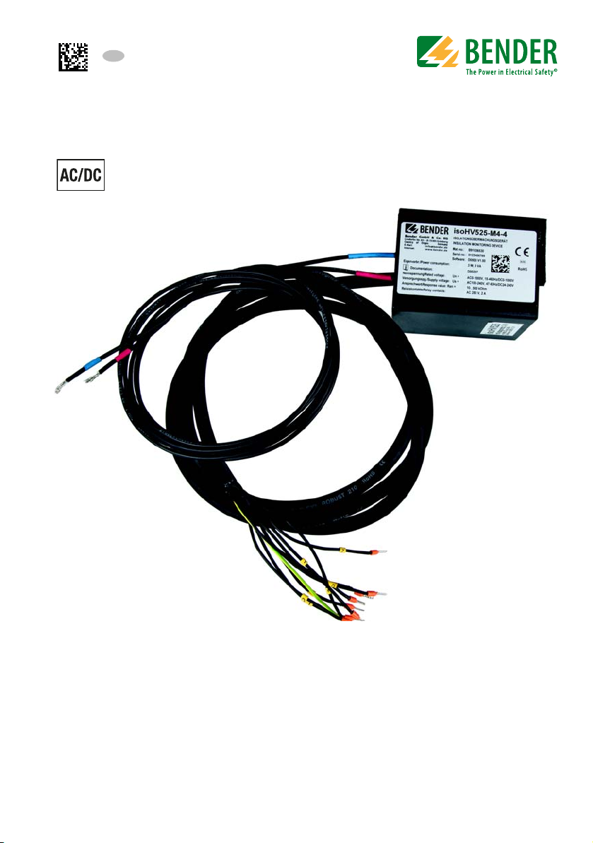
ISOMETER® isoHV525
Insulating monitoring device for unearthed
AC, AC/DC, and DC systems (IT systems)
up to 3(N)AC, AC/DC 0...1000 V or DC 0...1000 V
Software versions: D0500 V1.xx
D0453 V1.xx
isoHV525_D00297_04_M_XXEN/05.2018

Bender GmbH & Co. KG
P.O. Box 1161 • 35301 Gruenberg • Germany
Londorfer Str. 65 • 35305 Gruenberg • Germany
Tel.: +49 6401 807-0 • Fax: +49 6401 807-259
E-mail: info@bender.de • www.bender.de
Bender GmbH & Co. KG
©
All rights reserved.
Reprinting only with the permission of the publisher.
Subject to change!
Photos: Bender archive

Table of contents
1. Important information ........................................................................... 6
1.1 How to use this manual ................................................................................... 6
1.2 Technical support: Service and support .................................................... 7
1.2.1 First level support .............................................................................................. 7
1.2.2 Repair service ...................................................................................................... 7
1.2.3 Field service ......................................................................................................... 8
1.3 Training courses ................................................................................................. 8
1.4 Delivery conditions ........................................................................................... 8
1.5 Inspection, transport and storage ............................................................... 8
1.6 Warranty and liability ....................................................................................... 9
1.7 Disposal ................................................................................................................. 9
2. Safety instructions ............................................................................... 10
2.1 General safety instructions .......................................................................... 10
2.2 Work activities on electrical installations ................................................ 10
2.3 Intended use ..................................................................................................... 11
3. Function ................................................................................................. 12
3.1 isoHV525-M4-4 ................................................................................................. 12
3.1.1 Features .............................................................................................................. 12
3.1.2 Function description ...................................................................................... 12
3.1.2.1 Manual self test ............................................................................................... 12
3.1.2.2 Malfunction ...................................................................................................... 13
3.1.2.3 Signalling assignment of the alarm relays K1/K2 ............................... 13
3.1.2.4 Measuring and response times ................................................................. 13
3.1.2.5 External, combined Test or Reset button T/R ...................................... 13
3.1.2.6 Analogue output ............................................................................................ 14
3.2 isoHV525-S4-4 .................................................................................................. 15
3.2.1 Device features ................................................................................................. 15
isoHV525_D00297_04_M_XXEN/05.2018
3

Inhaltsverzeichnis
3.2.2 Function description ...................................................................................... 15
3.2.2.1 Manual self test ............................................................................................... 16
3.2.2.2 Malfunction ...................................................................................................... 17
3.2.2.3 Signalling assignment of the alarm relays K1/K2 ............................... 17
3.2.2.4 Measuring and response times ................................................................. 17
3.2.2.5 External, combined Test or reset button T/R ....................................... 18
3.2.2.6 Fault memory .................................................................................................. 18
3.2.2.7 Interface/protocols ....................................................................................... 19
4. Installation, connection and commissioning .................................. 21
4.1 Mounting ............................................................................................................ 21
4.2 Connecting the device .................................................................................. 21
4.3 Commissioning ................................................................................................ 25
5. isoHV525-S4-4 parameter overview ................................................. 26
5.1 Setting the response value .......................................................................... 26
5.2 Configuration of the relay operating mode ........................................... 26
5.2.1 Alarm assignment "r1" and "r2" .................................................................. 27
5.2.2 Fault memory configuration ...................................................................... 27
5.3 Interface configuration ................................................................................. 28
5.4 Time configuration ......................................................................................... 28
5.5 Function configuration ................................................................................. 29
5.6 Measured value description ........................................................................ 29
6. Data access to the isoHV525-S4-4 using the
BMS protocol ......................................................................................... 30
4
isoHV525_D00297_04_M_XXEN/05.2018

Inhaltsverzeichnis
7. Data access to the isoHV525-S4-4 using the
Modbus RTU protocol ......................................................................... 31
7.1 Reading the Modbus register from the ISOMETER® ........................... 31
7.1.1 Master device sends a command to the ISOMETER® .......................... 31
7.1.2 The ISOMETER®s answers the Master ....................................................... 31
7.2 Writing to the Modbus register (parameter setting) .......................... 32
7.2.1 Master device sends a command to the ISOMETER® .......................... 32
7.2.2 The ISOMETER®s answers the Master ....................................................... 32
7.3 Exception code ................................................................................................. 33
7.3.1 Structure of the exception code ................................................................ 33
8. ISOMETER® Modbus register assignment ........................................ 34
8.1 Device-specific data type of the ISOMETER® ......................................... 37
8.1.1 Device name ...................................................................................................... 37
8.1.2 Measured value ................................................................................................ 38
8.1.2.1 Float = Floating point value of the channels ....................................... 38
8.1.2.2 AT&T = Alarm type and test type (internal/external) ........................ 38
8.1.2.3 R&U = Range and unit .................................................................................. 39
8.1.3 Alarm assignment of the relays .................................................................. 40
8.2 Channel description ....................................................................................... 41
9. IsoData data string ............................................................................... 43
10. Technical data .................................................................................... 44
10.1 Tabular representation .................................................................................. 44
10.2 Standards, approvals and certifications .................................................. 48
10.3 Ordering information ..................................................................................... 48
isoHV525_D00297_04_M_XXEN/05.2018
5
1. Important information
1.1 How to use this manual
This manual is intended for qualified personnel working in electrical
engineering and electronics!
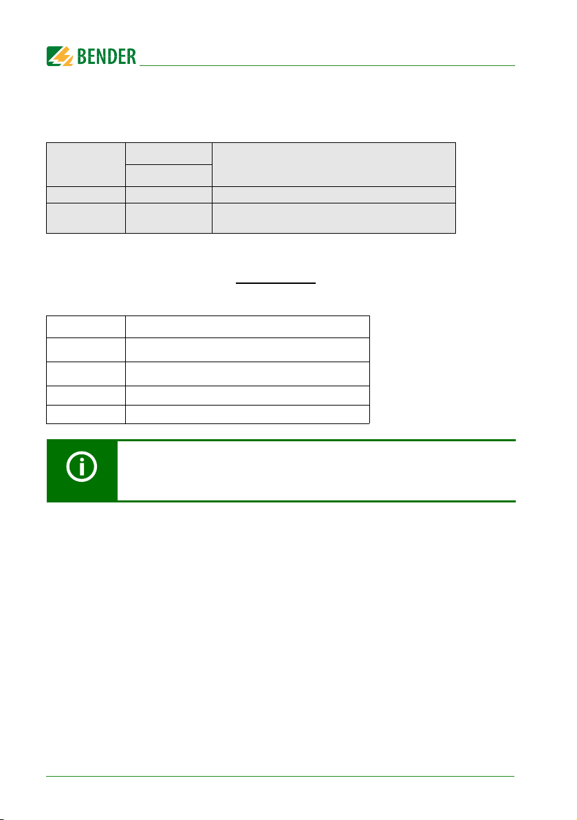
To make it easier for you to understand and revisit certain sections in this manual, we
have used symbols to identify important instructions and information. The meaning of
these symbols is explained below:
Th is s ign al wo rd i ndi cat es t hat t her e is a high risk of dang er t hat wil l re sult
DANGER
WARNING
CAUTION
in death or serious injury if not avoided.
This signal word indicates a medium risk of danger that can lead to death
or seriousinjury if not avoided.
This signal word indicates a low level risk that can result in minor or
moderate injury or damage to property if not avoided
This symbol denotes information intended to assist the user in making
optimum use of the product.
6
isoHV525_D00297_04_M_XXEN/05.2018

Important information
1.2 Technical support: Service and support
For commissioning and troubleshooting Bender offers you:
1.2.1 First level support
Technical support by phone or e-mail for all Bender products
Questions concerning specific customer applications
Commissioning
Troubleshooting
Telephone: +49 6401 807-760*
Fax: +49 6401 807-259
In Germany only: 0700BenderHelp (Tel. and Fax)
E-Mail: support@bender-service.com
1.2.2 Repair service
Repair, calibration, update and replacement service for Bender products
Repairing, calibrating, testing and analysing Bender products
Hardware and software update for Bender devices
Delivery of replacement devices in the event of faulty or incorrectly delivered
Bender devices
Extended warranty for Bender devices with in-house repair service or replace-
ment device at no extra cost
Telephone: +49 6401 807-780** (technical issues)
+49 6401 807-784**, -785** (sales)
Fax: +49 6401 807-789
E-Mail: repair@bender-service.com
Please send all devices for repair to the following address:
Bender GmbH, Repair service,
Londorfer Str. 65,
35305 Grünberg
isoHV525_D00297_04_M_XXEN/05.2018
7

Important information
1.2.3 Field service
On-site service for all Bender products
Commissioning, parameter setting, maintenance, troubleshooting for Bender
products
Analysis of the electrical installation in the building (power quality test, EMC test,
thermography)
Training courses for customers
Telephone: +49 6401 807-752**, -762 **(technical issues)/
+49 6401 807-753** (sales)
Fax: +49 6401 807-759
E-Mail: fieldservice@bender-service.com
Internet: www.bender-de.com
* Available from 7.00 a.m. to 8.00 p.m. 365 days a year (CET/UTC+1)
** Mo-Thu 7.00 a.m. - 8.00 p.m., Fr 7.00 a.m. - 13.00 p.m.
1.3 Training courses
Bender is happy to provide training regarding the use of test equipment.
The dates of training courses and workshops can be found on the Internet at
www.bender.de -> Know-how -> Seminars.
1.4 Delivery conditions
Bender sale and delivery conditions apply. For software products, the "Softwareklausel
zur Überlassung von Standard-Software als Teil von Lieferungen, Ergänzung und Änderung der Allgemeinen Lieferbedingungen für Erzeugnisse und Leistungen der Elektroindustrie" (software clause in respect of the licensing of standard software as part of
deliveries, modifications and changes to general delivery conditions for products and
services in the electrical industry) set out by the ZVEI (Zentralverband Elektrotechnikund Elektronikindustrie e.V.) applies. Sales and delivery conditions can be obtained
from Bender in printed or electronic format.
1.5 Inspection, transport and storage
Inspect the dispatch and equipment packaging for damage, and compare the contents
of the package with the delivery documents. In the event of damage in transit, please
contact Bender immediately. The devices must only be stored in areas where they are
protected from dust, damp, and spray and dripping water, and in which the specified
storage temperatures can be ensured.
8
isoHV525_D00297_04_M_XXEN/05.2018

Important information
1.6 Warranty and liability
Warranty and liability claims in the event of injury to persons or damage to property are
excluded if they can be attributed to one or more of the following causes:
Improper use of the device.
Incorrect mounting, commissioning, operation and maintenance of the device.
Failure to observe the instructions in this operating manual regarding transport,
commissioning, operation and maintenance of the device.
Unauthorised changes to the device made by parties other than the
manufacturer.
Non-observance of technical data.
Repairs carried out incorrectly and the use of replacement parts or accessories not
approved by the manufacturer.
Catastrophes caused by external influences and force majeure.
Mounting and installation with device combinations not recommended by the
manufacturer.
This operating manual, especially the safety instructions, must be observed by all personnel working on the device. Furthermore, the rules and regulations that apply for accident prevention at the place of use must be observed.
1.7 Disposal
Abide by the national regulations and laws governing the disposal of this device. Ask
your supplier if you are not sure how to dispose of the old equipment.
The directive on waste electrical and electronic equipment (WEEE directive) and the directive on the restriction of certain hazardous substances in electrical and electronic
equipment (RoHS directive) apply in the European Community. In Germany, these policies are implemented through the "Electrical and Electronic Equipment Act" (ElektroG).
According to this, the following applies:
Electrical and electronic equipment are not part of household waste.
Batteries and accumulators are not part of household waste and must be dispo-
sed of in accordance with the regulations.
Old electrical and electronic equipment from users other than private households
which was introduced to the market after 13th August 2005 must be taken back
by the manufacturer and disposed of properly.
For more information on the disposal of Bender devices, refer to our homepage at
www.bender.de -> Service & support.
isoHV525_D00297_04_M_XXEN/05.2018
9
2. Safety instructions
2.1 General safety instructions
Part of the device documentation in addition to this manual is the enclosed "Safety instructions for Bender products".
2.2 Work activities on electrical installations
Only skilled persons are permitted to carry out the work necessary to
install, commission and run a device or system.
Risk of electrocution due to electric shock!
Touching live parts of the system carries the risk of:
DANGER
If the device is used outside the Federal Republic of Germany, the applicable local standards and regulations must be complied with. The European standard EN 50110 can be
used as a guide.
An electric shock
Damage to the electrical installation
Destruction of the device
Before installing and connecting the device, make sure that the
installation has been de-energised. Observe the rules for working on
electrical installations.
10
isoHV525_D00297_04_M_XXEN/05.2018
Safety instructions
2.3 Intended use
Only skilled persons are permitted to carry out the work necessary
to install, commission and run a device or system.
The isoHV525 ISOMETER® monitors the insulation resistance RF of unearthed AC, AC/DC
and DC systems (IT systems) with nominal system voltages of 3(N)AC,
AC/DC 0 … 1000 V or DC 0 …1000 V. The maximum permissible system leakage capacitance C
ting characteristics, when a minimum load current of DC 100 mA flows. A separate
supply voltage U
Please heed the limits of the area of application indicated in the technical specifications.
Any use other than that described in this manual is regarded as improper.
is 150 µF. DC components existing in AC systems do not influence the opera-
e
allows de-energised systems to be monitored, too.
s
To ensure that the ISOMETER® functions correctly, an internal resistance of
≤ 1 kΩ must exist between L1/+ and L2/- via the source (e.g. the
transformer) or the load.
In the event of an alarm message of the ISOMETER®, the insulation fault
should be eliminated as quickly as possible.
If the ISOMETER® is installed inside a control cabinet, the insulation fault
message must be audible and/or visible to attract attention.
Two variants of the isoHV525 ISOMETER®s are available:
isoHV525-M4-4 with an analog output
isoHV525-S4-4 with a serial interface
isoHV525_D00297_04_M_XXEN/05.2018
11

3. Function
3.1 isoHV525-M4-4
3.1.1 Features
Monitoring the insulation resistance R
Automatic adaptation to the system leakage capacitance C
Two separate response values for Alarm 1 and Alarm 2
Alarms are signalled via alarm relays ("K1", "K2")
0. . . 10 V analogue output (galvanically separated)
3.1.2 Function description
The ISOMETER® measures the insulation resistance RF and the system leakage capacitance C
between the system to be monitored (L1/+, L2/-) and earth (PE). If the value RF
e
exceeds the set response values, this will be indicated by the relays "K1" and "K2".
If the insulation resistance R
exceeds the release value (response value plus hysteresis),
F
the alarm relays switch back to their initial position.
The device function can be tested using the Test/Reset button.
The isoHV525 determines the system leakage capacitance via an
impedance measurement whose frequency is adjusted to the most
accurate insulation measurement. The measurement signal is influenced
by rectifiers or inverters, and can lead to phase errors which in turn can
lead to a distorted system leakage capacitance value.
for unearthed AC/DC systems
F
up to 150 µF
e
3.1.2.1 Manual self test
The integrated self test function tests the function of the insulation monitoring device
and the connection to earth. A self test is started by pressing the external Test/Reset
button. Relay 1 ("K1") is switched during a manual self test. In the event of a fault, relay
2 ("K2") switches and the measuring function is interrupted.
Internal device errors can be caused by external disturbances or internal hardware errors. After eliminating the fault, the alarm relays are automatically reset or are reset to
the initial position by pressing the Test/Reset button. The self test can take a few minutes.
12
isoHV525_D00297_04_M_XXEN/05.2018

Function
3.1.2.2 Malfunction
In addition to the described self test, several functions in the insulation monitoring device are continuously checked during operation. If the error occurs again after restarting the device, then contact Bender Service.
3.1.2.3 Signalling assignment of the alarm relays K1/K2
Pre-alarm and test are assigned to relay 1 ("K1"). The main alarm and device fault are assigned to relay 2 ("K2").
3.1.2.4 Measuring and response times
The measuring time is the period essential for the detection of the measured value. The
measuring time is reflected in the operating time t
. The measuring time for the insu-
ae
lation resistance value is mainly determined by the required measuring pulse duration,
which depends on the insulation resistance and system leakage capacitance of the system to be monitored. The measuring pulse is produced by the measuring voltage generator, which is integrated in the ISOMETER®. System disturbances may lead to
extended measuring times.
Operating time t
ae
The operating time tae is the time required by the ISOMETER® to determine the measured value. For the measured insulation resistance value, it is dependent on the insulation resistance and the system leakage capacitance.
3.1.2.5 External, combined Test or Reset button T/R
Reset= Press the external button < 1.5 s
Reset followed by a test = Press the external button > 1.5 s
Stop measuring function = Press and hold the external button
Only one ISOMETER® may be controlled via an external Test/Reset button. A galvanic
parallel connection of several test or reset inputs for testing multiple insulation monitoring devices is not allowed.
isoHV525_D00297_04_M_XXEN/05.2018
13
Function
3.1.2.6 Analogue output
The isoHV-M4-4 ISOMETER® outputs and analogue voltage in the range 0. . .10 V .
Activation
on 120 k
FAC
U 0 . . . 10 V 0 . . . 10 V, Permissible load > 20 k
The scaled reference value for thr displayed nonlinear resistance at 50% of interface control..
Description
Calculation of the insulation resistance using the analogue output:
Setting
R
(kΩ) =
F
A₁ x R
A
SKM
(kΩ)
- R
SKM
(kΩ)
Variable Description
R
R
SKM
A
A
Insulation fault in k
F
Scaled reference value in k (i.e. 120 k)
Upper analogue output value (i.e. 10 V)
1
Measured analogue output value
2
The analog output provides stable output values only after the
isoHV525-M4-4 has been initialized.
14
isoHV525_D00297_04_M_XXEN/05.2018

Function
3.2 isoHV525-S4-4
3.2.1 Device features
Monitoring the insulation resistance R
Measurement of the nominal system voltage U
and overvoltage detection
Measurement of residual voltages to earth (L1+/PE and L2-/PE)
Automatic adaptation to the system leakage capacitance C
Two separate response values for Alarm 1 and Alarm 2
Alarm are signalled via alarm relays ("K1", "K2")
Selectable N/C or N/O relay operation
Selectable start-up delay, response delay and delay on release
Fault memory can be activated.
RS-48 5 (galvanically isolated) with the following protocols:
– BMS interface (Bender measuring device interface) for data exchange with
other Bender components
– Modbus RTU
– IsoData (for continuous data output)
3.2.2 Function description
The ISOMETER® measures the insulation resistance RF and the system leakage capacitance C
of the nominal system voltage U
ges U
between the system to be monitored (L1/+, L2/-) and earth (PE). The RMS value
e
(between L1/+ and earth) and U
L1e
between L1/+ and L2/-, as well as the residual volta-
n
red. From a minimum value of the nominal system voltage, the ISOMETER® determines
the faulty conductor L1/+ or L2/-, which shows the distribution of the insulation resistance between conductors L1/+ and L2/-.
The value range of the faulty conductor is
for unearthed AC/DC systems
F
(True RMS) with undervoltage
n
up to 150 µF
e
(between L2/- and earth) are also measu-
L2e
±100 %:
Display Meaning
-100 % One-sided fault on conductor L2/0 % Symmetrical fault
+100 % One-sided fault on conductor L1/+
isoHV525_D00297_04_M_XXEN/05.2018
15
Function
The partial resistances can be calculated from the total insulation resistance RF and the
faulty conductor (R %) using the following formula:
If the values R
Fault on conductor L1/+ ->R
Fault on conductor L2/- -> R
or Un exceeds the set response values, this will be indicated by the relays
F
= (200 % * RF)/(100 % + R %)
L1F
= (200 % * RF)/(100 % – R %)
L2F
"K1" and "K2". In addition, the operation of the relay (n.c./n.o.) can be set and the fault
memory "M", activated. If the values R
plus hysteresis) uninterrupted for no longer than the period t
or Un exceed their release value (response value
F
, then the alarm relays
off
will switch back to their initial position. If the fault memory is enabled, the alarm relays
remain in the alarm state until the external Test/Reset button is pressed or until the supply voltage U
button. Device parameters are initially assigned by Bender. Parameterisation of the ISOMETER
Ethernet gateway (COM465IP) or Modbus RTU
is switched off. The device function can be tested using the Test/Reset
s
isoHV525-S4-4 is also possible via the BMS bus, for example by means of a BMS-
.
The isoHV525 determines the system leakage capacitance via an
impedance measurement whose frequency is adjusted to the most
accurate insulation measurement. The measurement signal is influenced
by rectifiers or inverters, and can lead to phase errors which in turn can
lead to a distorted system leakage capacitance value.
3.2.2.1 Manual self test
The integrated self test function tests the function of the insulation monitoring device
and the connection to IT system to be monitored. A self test is started by pressing the
external test/reset button. Relay 1 ("K1") is switched during a manual self test. In the
event of a fault, relay 2 ("K2") switches and the measuring function is interrupted.
Internal device errors can be caused by external disturbances or internal hardware errors. After eliminating the fault, the alarm relays are automatically reset or are reset to
the initial position by pressing the Test/Reset button. The self test can take a few minutes.
16
isoHV525_D00297_04_M_XXEN/05.2018
 Loading...