

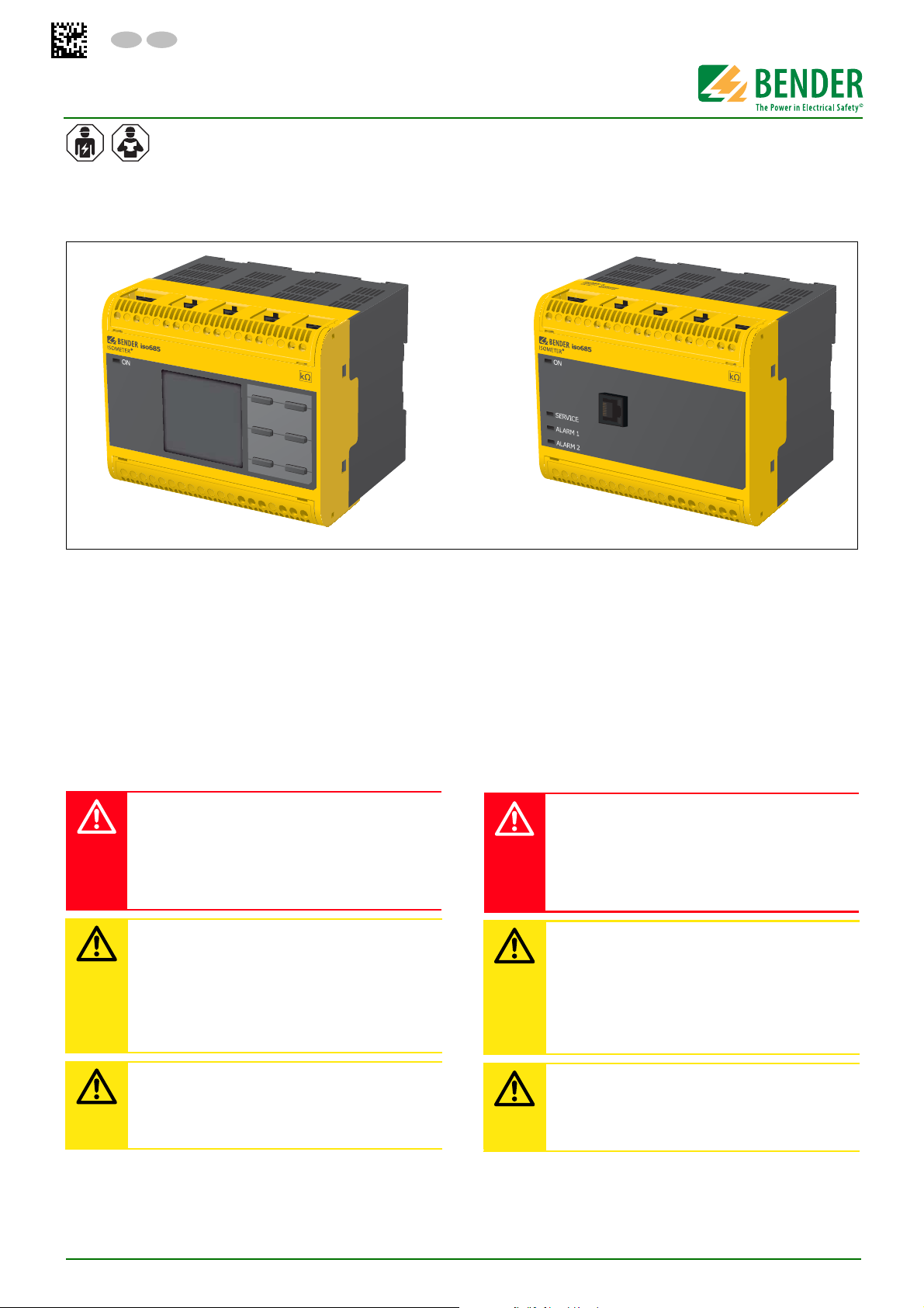
Bender ISOMETER isoHR685W Series, ISOMETER isoHR685W-S-I-B, ISOMETER isoHR685W-D-I-B Quick Start Manual
DE EN
isoHR685W–D–I–B isoHR685W–S–I–B
Kurzanleitung/Quickstart
ISOMETER® isoHR685W-x-I-B
Isolationsüberwachungsgerät
Diese Kurzanleitung gilt für die folgenden Gerätevarianten und
ersetzt nicht das Handbuch.
Bestimmungsgemäße Verwendung
Das ISOMETER® isoHR685W-x-I-B überwacht den Isolationswiderstand von ungeerdeten AC/DC-Hauptstromkreisen (IT-Systemen) mit Netznennspannungen von AC, AC/DC 0… 1000 V oder
DC 0…1300 V.
Die in AC/DC-Systemen vorhandenen gleichstromgespeisten
Komponenten haben keinen Einfluss auf das Ansprechverhalten.
Durch die separate Versorgungsspannung ist auch die Überwachung eines spannungs-losen Systems möglich. Die maximal
zulässige Netzableitkapazität beträgt abhängig vom anwendungsspezifischen Profil bis zu 1000 μF.
Insulation monitoring device
This quickstart guide applies to th following device variants does
not replace the operating manual.
Intended use
The ISOMETER® isoHR685W-x-I-B monitors the insulation resistance of unearthed AC/DC main circuits (IT systems)with mains
voltages of AC, AC/DC 0…1000 V or DC 0…1300 V.
DC components existing in AC/DC systems do not influence the
operating characteristics. A separate supply voltage allows deenergised systems to be monitored. The maximum permissible
system leakage capacitance is 1000 μF and is dependent on the
application-specific profile.
Sicherheitshinweise
Gefahr eines elektrischen Schlages!
An den Klemmen liegt eine hohe Spannung an, die bei
GEFAHR
direkter Berührung lebensgefährlich ist. Ist das Gerät mit
den Klemmen L1/+, L2, L3/- an ein betriebsbedingt spannungsführendes IT-System angeschlossen, dürfen die
Klemmen KE und E nicht vom Schutzleiter (PE) getrennt
werden.
Sachschaden durch unsachgemäße Installation!
Die Anlage kann Schaden nehmen, wenn Sie in einem
VORSICHT
leitend verbundenen System mehr als ein Isolationsüberwachungsgerät anschließen. Sind mehrere Geräte
angeschlossen, funktioniert das Gerät nicht und meldet
keine Isolationsfehler. Schließen Sie in jedem leitend
verbundenen System nur ein Isolationsüberwachungsgerät an.
Trennung vom IT-System!
Bei Isolations- und Spannungsprüfungen an der Anlage
VORSICHT
muss das Isolationsüberwachungsgerät für die Dauer
der Prüfung vom IT-System getrennt sein. Andernfalls
kann das Gerät Schaden nehmen.
Safety instructions
High risk of electric shock!
The terminals carry high voltage and direct contact with
DANGER
these terminals will likely result in electrocution. If the
terminals L1/+, L2, L3/- of the device are connected to a
live IT system, the terminals E and KE must not be disconnected from the protective conductor (PE).
Damage to property due to incorrect installation!
There should only be one insulation monitoring device
CAUTION
per conductively connected installation. Damage to the
installation may result if several insulation monitoring
devices are connected. In addition, the device will not
function and will not report an insulation fault if more
than one insulation monitoring device is connected.
Disconnect from the IT system!
The insulation monitoring device must be disconnected
CAUTION
from the IT system before insulation or voltage tests at
the installation and must remain so for the duration of
the test. Otherwise the device may be damaged.
isoHR685W-x-I-B_D00261_04_Q_DEEN/12.2019
1
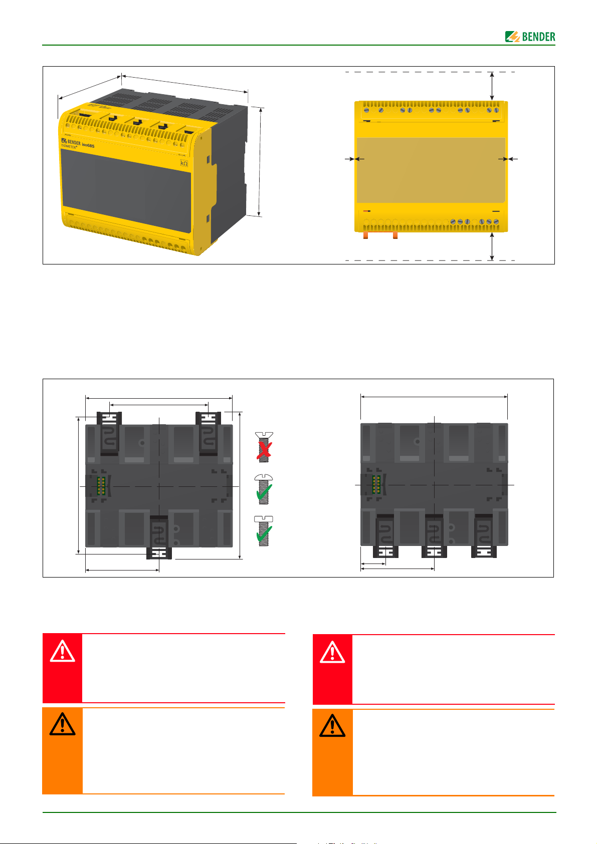
ISOMETER® isoHR685W-x-I-B
93
108
0 mm
108
107, 3
100
108
Montage
110
Montage auf Hutschiene
Rasten Sie alle 3 mitgelieferten Montageclips (2 separat verpackt)
des Geräts auf der Hutschiene unten so ein, dass ein sicherer und
fester Sitz gewährleistet ist.
Schraubbefestigung
Bringen Sie die 3 mitgelieferten Montageclips (2 separat verpackt) manuell oder mit Werkzeug in eine über das Gehäuse hinaus ragende Rastposition. Befestigen Sie das Gerät mit drei M4Schrauben (kein Senkkopf), siehe nachfolgende Skizze.
Screw mounting
72
Installation
20 mm
0 mm
20 mm
DIN rail mounting:
Snap all 3 mounting clips delivered with the device (2 of them packed separately) onto the DIN rail in such a way that a safe and
tight fit is ensured.
Screw mounting
Install the three accompanying mounting clips (2 are packed separately) manually or with a tool in a way that they protrude beyond the enclosure. Fix the device by means of three M4 screws
(no counter sunk screw) as shown in the following pictures.
DIN rail mounting
54
Anschluss
Verdrahten Sie das Gerät gemäß Anschlussplan. Beachten Sie dabei die technischen Daten. Montieren Sie nach dem Anschluss
die obere und die untere mitgelieferte Klemmenabdeckung!
Gefahr eines elektrischen Schlages!
An den Klemmen L1/+…L3/- können Nennspannungen
GEFAHR
bis 1300 V anliegen, die bei direkter Berührung lebensgefährlich sein können. Nehmen Sie das Gerät nur mit
montierten und eingerasteten Klemmenabdeckungen
in Betrieb.
Verletzungen, Brände und Sachschäden durch Kurzchluss!
Entsprechend DIN VDE 0100-430 können Sie auf
WARNUNG
Schutzeinrichtungen zum Schutz bei Kurzschluss für die
Ankopplung der Klemmen L1/+, L2, L3/- an das zu
überwachende IT-System verzichten, wenn die Leitung
oder das Kabel so ausgeführt ist, dass die Gefahr eines
Kurzschlusses auf ein Mindestmaß beschränkt ist.
Achten Sie auf kurz- und erdschlussfeste Verlegung.
2
18
54
Connection
Wire up the device according to the wiring diagram taking account of the technical data. After connecting the device, install
the enclosed upper and lower terminal cover!
High risk of electric shock!
A nominal voltage of up to 1300 V may be present at the
DANGER
terminals L1/+…L3/–. Direct contact with these will
likely result in electrocution. Make sure the terminal covers are properly mounted and clicked in before putting
the device into operation.
Injury, fire and damage to property due to a short circuit!
When coupling the terminals L1/+, L2, L3/- to the IT sys-
WARNING
tem ≤690 V to be monitored, devices for protection
against a short-circuit can be omitted according to
IEC 60364-4-43:2008 or DIN VDE 0100430 if the wiring is
carried out in such a way as to reduce the risk of a shortcircuit to a minimum. The use of short-circuit proof and
earth-fault proof wiring is recommended.
isoHR685W-x-I-B_D00261_04_Q_DEEN/12.2019
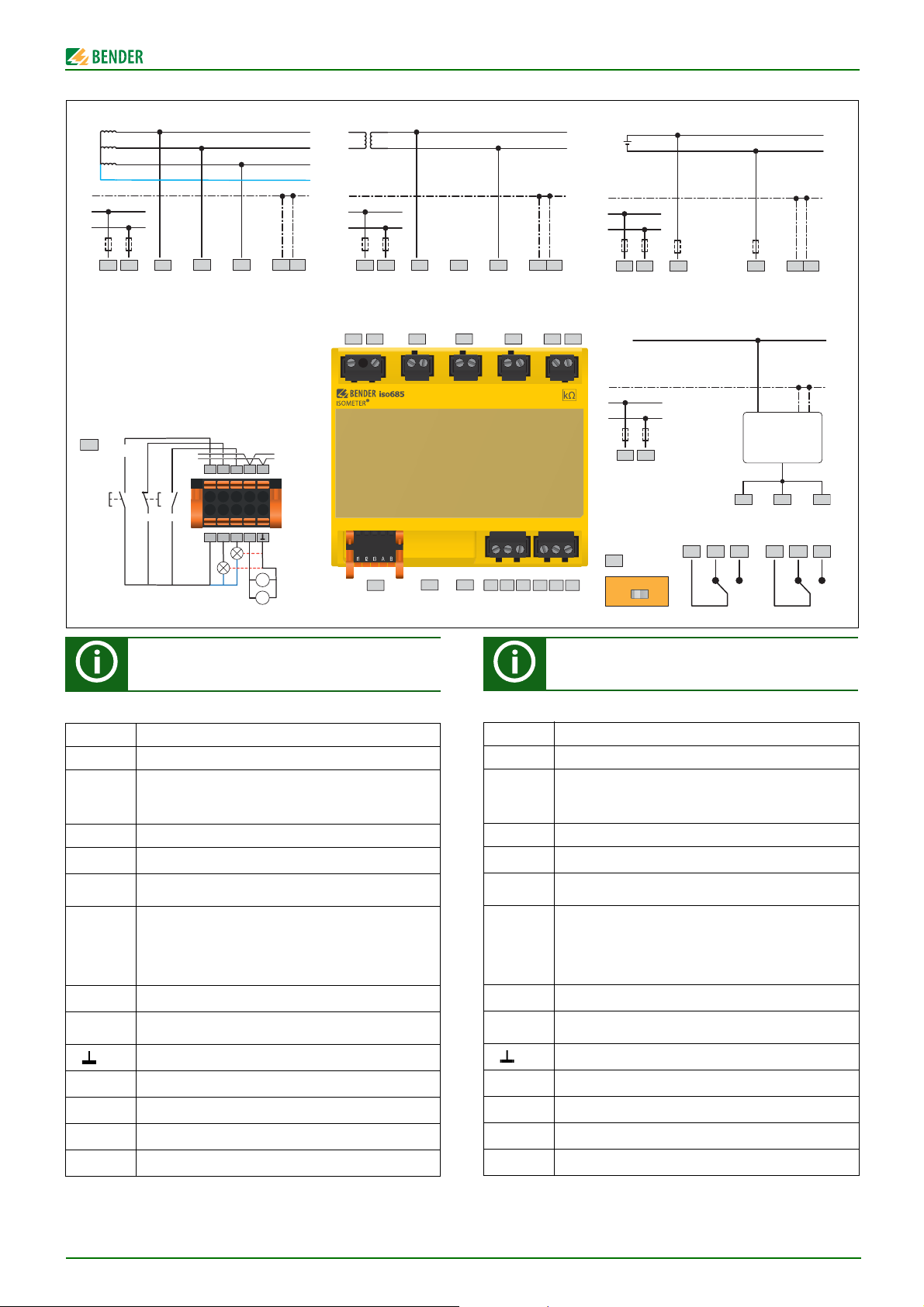
ISOMETER® isoHR685W-x-I-B
L1
Voltagemeter
Currentmeter
X1
active adjustable
L3/-
L2
L1/+
Anschlussplan
3NAC AC DC
U
n
U
S
*
L2
I2
I1
+
Q1
Q2
passive adjustable
L3/-
A
M+
Deactivate
high
active
Device
RESET
L1/+A2/–A1/+
low
active
TEST
+24 V
L1
L2
L3
N
U
n
U
S
*
KE
E
RS-485
BI3
A
V
L1/+A2/–A1/+
L1/+A2/–A1/+
X1
ETH R
Wiring diagram
L2
L3/-
L2
L2L1L2
KE
E
KE
L3/-
141211
U
n
U
S
*
iso685W-x-I-B + AGHxxxx
E
U
S
A2/–A1/+
R
242221
R
OFF ON
L1/+A2/–A1/+
*
*
Un > 690 V
=> F 2A
*
L3/-
AGH xxxx
U
n(IT-System)
U
n(isoxx685...)
21 22 2411 12 14
KE
IT-System
>
L+
L−
E
**Leitungsschutz vorsehen!
Gemäß der DIN VDE 0100-430 ist bei der Versorgungsspannung ein Leitungsschutz vorzusehen.
Legende zum Anschlussplan
Klemme Anschlüsse
A1/+ A2/-
L1/+
L3/-
Stromversorgung, U
Anschlüsse an das zu überwachende Netz
L2
AC, 0…1000 V; 3AC, 0…690 V; DC, 0…1300 V
KE E Anschluss an Erde
I1…I3 (X1) Konfigurierbare digitale Eingänge (z. B. Test, Reset, …)
A, B (X1)
Serielle Schnittstelle RS-485 (BS-Bus)
Terminierung mittels DIP-Schalter R .
Versorgungsspannung der Ein- und Ausgänge I, Q und M.
Elektr. Überlastschutz. Autom. Abschaltung bei Kurz-
+ (X1)
schluss und Transiente (rücksetzbar).
Bei Versorgung über ein externes 24-V-Netzteil dürfen
A1/+, A2/- nicht angeschlossen werden.
Q1, Q2 (X1) Konfigurierbarer digitaler Ausgang
M+ (X1)
Konfigurierbarer analoger Ausgang (z. B. Messinstrument)
Bezugspotential Masse
(X1)
RJ45 (ETH) Ethernet-Anschluss, Webserver, Modbus, IP
R Terminierung für den BS-Bus
11 12 14 Relais 1
21 22 24 Relais 2
= 24…240V (50…400 Hz)
s
**Provide line protection!
According to DIN VDE 0100-430, a line protection shall
be provided for the supply voltage.
Legend to terminal diagram
Terminal Connections
A1/+ A2/-
L1/+
Power supply, U
Connections to the system to be monitored
L2
AC, 0…1000 V; 3AC, 0…690 V; DC, 0…1300 V
L3/-
KE E Connection to ground
I1…I3 (X1) Configurable digital inputs (e.g. Test, Reset,…)
A, B (X1)
Serial interface RS-485 (BS bus)
termination by means of a DIP switch R
Supply voltage of the inputs and outputs I, Q and M.
Electrical overload protection. Automatic shutdown in the
+ (X1)
event of a short circuit and transient (resettable).
If the supply is via an external 24 V source, then A1/+,
A2/- must not be connected.
Q1, Q2 (X1) Configurable digital output
M+ (X1)
Configurable analogue output (e.g. measuring instrument)
Reference potential ground
(X1)
RJ45 (ETH) Ethernet connection, webserver, modbus, IP
R Termination for the BS bus
11 12 14 Relay 1
21 22 24 Relay 2
= 24…240V (50…400 Hz)
s
isoHR685W-x-I-B_D00261_04_Q_DEEN/12.2019
3
 Loading...