

Bender ISOMETER iso685W-S-B, ISOMETER iso685-S-B, ISOMETER iso685-D-B, ISOMETER iso685W-D-B User Manual
EN
Manual
ISOMETER®
iso685-D-B
iso685W-D-B
iso685-S-B
iso685W-S-B
Insulation Monitoring Device for IT AC systems
with galvanically connected rectifiers and inverters
and for IT DC systems
iso685-D-B_D00177_01_M_XXEN/01.2016

PLEASE READ THIS MANUAL AND ANY ACCOMPANYING DOCUMENTS CAREFULLY
AND KEEP THEM IN A SECURE PLACE FOR FUTURE REFERENCE.
Bender GmbH & Co. KG
P.O. Box 1161 • 35301 Gruenberg • Germany
Londorfer Straße 65 • 35305 Gruenberg • Germany
Tel.: +49 6401 807-0
Fax: +49 6401 807-259
Email: info@bender.de
Web: www.bender.de
Customer service:
Service hotline: 0700-BenderHelp (Telephone and Fax)
Carl-Benz-Straße 8 • 35305 Gruenberg • Germany
Tel.:+49 6401 807-760
Fax:+49 6401 807-629
Email: info@bender-service.com
© Bender GmbH & Co. KG
All rights reserved.
Reproduction only with permission
of the publisher.
Subject to change.

Table of contents
1. Safety instructions ........................................................ 7
1.1 Explanation of symbols and notes . . . . . . . . . . . . . . . . . . . . . 7
1.2 Intended use . . . . . . . . . . . . . . . . . . . . . . . . . . . . . . . . . . . . . . . . . 7
1.3 Warranty and liability . . . . . . . . . . . . . . . . . . . . . . . . . . . . . . . . . 8
1.3.1 Personnel . . . . . . . . . . . . . . . . . . . . . . . . . . . . . . . . . . . . . . . . 8
1.3.2 About the operating manual . . . . . . . . . . . . . . . . . . . . . . 8
1.3.3 Hazards when handling the ISOMETER®
iso685-D-B/-S-B . . . . . . . . . . . . . . . . . . . . . . . . . . . . . . . . . . 8
1.3.4 Inspection, transport and storage . . . . . . . . . . . . . . . . . 8
1.3.5 Note . . . . . . . . . . . . . . . . . . . . . . . . . . . . . . . . . . . . . . . . . . . . . 8
2. Function ......................................................................... 9
2.1 Features . . . . . . . . . . . . . . . . . . . . . . . . . . . . . . . . . . . . . . . . . . . . . . 9
2.2 Product description . . . . . . . . . . . . . . . . . . . . . . . . . . . . . . . . . . . 9
2.3 Special characteristics ISOMETER® iso685-S-B with
front panel . . . . . . . . . . . . . . . . . . . . . . . . . . . . . . . . . . . . . . . . . 9
2.4 Functional description . . . . . . . . . . . . . . . . . . . . . . . . . . . . . . . . 9
2.5 Interfaces. . . . . . . . . . . . . . . . . . . . . . . . . . . . . . . . . . . . . . . . . . . . 10
2.6 Self-test . . . . . . . . . . . . . . . . . . . . . . . . . . . . . . . . . . . . . . . . . . . . . 10
3. Device overview .......................................................... 11
3.1 Dimensions. . . . . . . . . . . . . . . . . . . . . . . . . . . . . . . . . . . . . . . . . . 11
3.2 Device variants . . . . . . . . . . . . . . . . . . . . . . . . . . . . . . . . . . . . . . 12
3.3 Connections and panel . . . . . . . . . . . . . . . . . . . . . . . . . . . . . . 13
4. Mounting ...................................................................... 14
4.1 Screw mounting . . . . . . . . . . . . . . . . . . . . . . . . . . . . . . . . . . . . . 14
4.2 DIN rail mounting. . . . . . . . . . . . . . . . . . . . . . . . . . . . . . . . . . . . 14
5. Connection ...................................................................15
5.1 Connection conditions. . . . . . . . . . . . . . . . . . . . . . . . . . . . . . . 15
5.2 Connection to a 3(N)AC system/system type 3AC . . . . . 16
5.3 Connection to an AC system/system type AC . . . . . . . . . 16
5.4 Connection to a DC system/system type DC . . . . . . . . . . 17
5.5 Connection to the X1 interface . . . . . . . . . . . . . . . . . . . . . . . 17
5.6 Connection to the supply voltage . . . . . . . . . . . . . . . . . . . . 18
5.6.1 Connection to A1/+, A2/- . . . . . . . . . . . . . . . . . . . . . . . . 18
5.6.2 Connection to X1 . . . . . . . . . . . . . . . . . . . . . . . . . . . . . . . . 18
5.7 Connection to the Ethernet interface . . . . . . . . . . . . . . . . . 19
5.8 Connection to the relay 1 interface (11 12 14) . . . . . . . . 19
5.9 Connection to the relay-2 interface (21 22 24). . . . . . . . 20
6. Commissioning ........................................................... 20
6.1 Device buttons . . . . . . . . . . . . . . . . . . . . . . . . . . . . . . . . . . . . . . 20
6.2 General initial commissioning process . . . . . . . . . . . . . . . 20
6.3 Initial commissioning . . . . . . . . . . . . . . . . . . . . . . . . . . . . . . . . 21
6.3.1 Set language . . . . . . . . . . . . . . . . . . . . . . . . . . . . . . . . . . . . 21
6.3.2 Set time and date . . . . . . . . . . . . . . . . . . . . . . . . . . . . . . . . 21
6.3.3 Set system type . . . . . . . . . . . . . . . . . . . . . . . . . . . . . . . . . 21
6.3.4 Set profile . . . . . . . . . . . . . . . . . . . . . . . . . . . . . . . . . . . . . . . 22
6.3.5 Set response value Ran1 for Alarm 1 . . . . . . . . . . . . . 22
6.3.6 Set response value Ran2 for Alarm 2 . . . . . . . . . . . . . 22
6.4 Recommissioning. . . . . . . . . . . . . . . . . . . . . . . . . . . . . . . . . . . . 22
3
iso685-D-B_D00177_01_M_XXEN/01.2016

Table of contents
7. Display .......................................................................... 23
7.1 Standarddisplay . . . . . . . . . . . . . . . . . . . . . . . . . . . . . . . . . . . . . 23
7.2 Fault display (active) . . . . . . . . . . . . . . . . . . . . . . . . . . . . . . . . . 23
7.3 Fault display (inactive) . . . . . . . . . . . . . . . . . . . . . . . . . . . . . . . 24
7.4 Acknowledge fault message . . . . . . . . . . . . . . . . . . . . . . . . . 25
7.5 Data-isoGraph . . . . . . . . . . . . . . . . . . . . . . . . . . . . . . . . . . . . . . . 25
7.6 History memory . . . . . . . . . . . . . . . . . . . . . . . . . . . . . . . . . . . . . 26
8. Menu .............................................................................27
1. Alarm settings . . . . . . . . . . . . . . . . . . . . . . . . . . . . . . . . . . . . . . . . . . . . 28
1.1 Insulation alarm. . . . . . . . . . . . . . . . . . . . . . . . . . . . . . . . . . . . . . . . . 28
1.1.1 Alarm 1 . . . . . . . . . . . . . . . . . . . . . . . . . . . . . . . . . . . . . . . . . . . . . . 28
1.1.2 Alarm 2 . . . . . . . . . . . . . . . . . . . . . . . . . . . . . . . . . . . . . . . . . . . . . . 28
1.1.3 Fault memory . . . . . . . . . . . . . . . . . . . . . . . . . . . . . . . . . . . . . . . . 28
1.2 Profile . . . . . . . . . . . . . . . . . . . . . . . . . . . . . . . . . . . . . . . . . . . . . . . . . . 28
1.3 System type . . . . . . . . . . . . . . . . . . . . . . . . . . . . . . . . . . . . . . . . . . . . 28
1.4 ISONet. . . . . . . . . . . . . . . . . . . . . . . . . . . . . . . . . . . . . . . . . . . . . . . . . . 28
1.4.1 ISONet . . . . . . . . . . . . . . . . . . . . . . . . . . . . . . . . . . . . . . . . . . . . . . . 28
1.4.2 Number of devices . . . . . . . . . . . . . . . . . . . . . . . . . . . . . . . . . . . 28
1.5 Device. . . . . . . . . . . . . . . . . . . . . . . . . . . . . . . . . . . . . . . . . . . . . . . . . . 29
1.6 T(Start) . . . . . . . . . . . . . . . . . . . . . . . . . . . . . . . . . . . . . . . . . . . . . . . . . 29
1.7 Coupling monitoring. . . . . . . . . . . . . . . . . . . . . . . . . . . . . . . . . . . . 29
1.8 Inputs . . . . . . . . . . . . . . . . . . . . . . . . . . . . . . . . . . . . . . . . . . . . . . . . . . 29
1.8.1 Digital 1 . . . . . . . . . . . . . . . . . . . . . . . . . . . . . . . . . . . . . . . . . . . . . . 29
1.8.1.1 Mode . . . . . . . . . . . . . . . . . . . . . . . . . . . . . . . . . . . . . . . . . . . . . . . . . . . 29
1.8.1.2 t(on) . . . . . . . . . . . . . . . . . . . . . . . . . . . . . . . . . . . . . . . . . . . . . . . . . . . . 29
1.8.1.3 t(off) . . . . . . . . . . . . . . . . . . . . . . . . . . . . . . . . . . . . . . . . . . . . . . . . . . . . 29
1.8.1.4 Function . . . . . . . . . . . . . . . . . . . . . . . . . . . . . . . . . . . . . . . . . . . . . . . . 29
1.8.2 Digital 2 . . . . . . . . . . . . . . . . . . . . . . . . . . . . . . . . . . . . . . . . . . . . . . 29
1.8.3 Digital 3 . . . . . . . . . . . . . . . . . . . . . . . . . . . . . . . . . . . . . . . . . . . . . . 29
1.9 Outputs . . . . . . . . . . . . . . . . . . . . . . . . . . . . . . . . . . . . . . . . . . . . . . . . 30
1.9.1 Relay 1 . . . . . . . . . . . . . . . . . . . . . . . . . . . . . . . . . . . . . . . . . . . . . . . 30
1.9.1.1 TEST . . . . . . . . . . . . . . . . . . . . . . . . . . . . . . . . . . . . . . . . . . . . . . . . . . . . 30
1.9.1.2 Relay mode . . . . . . . . . . . . . . . . . . . . . . . . . . . . . . . . . . . . . . . . . . . . . 30
1.9.1.3 Function 1. . . . . . . . . . . . . . . . . . . . . . . . . . . . . . . . . . . . . . . . . . . . . . . 30
1.9.1.4 Function 2. . . . . . . . . . . . . . . . . . . . . . . . . . . . . . . . . . . . . . . . . . . . . . . 30
1.9.1.5 Function 3. . . . . . . . . . . . . . . . . . . . . . . . . . . . . . . . . . . . . . . . . . . . . . . 30
1.9.2 Relay 2 . . . . . . . . . . . . . . . . . . . . . . . . . . . . . . . . . . . . . . . . . . . . . . . 30
1.9.3 Digital 1 . . . . . . . . . . . . . . . . . . . . . . . . . . . . . . . . . . . . . . . . . . . . . . 31
1.9.3.1 TEST . . . . . . . . . . . . . . . . . . . . . . . . . . . . . . . . . . . . . . . . . . . . . . . . . . . . 31
1.9.3.2 Mode . . . . . . . . . . . . . . . . . . . . . . . . . . . . . . . . . . . . . . . . . . . . . . . . . . . 31
1.9.3.3 Function 1. . . . . . . . . . . . . . . . . . . . . . . . . . . . . . . . . . . . . . . . . . . . . . . 31
1.9.3.4 Function 2. . . . . . . . . . . . . . . . . . . . . . . . . . . . . . . . . . . . . . . . . . . . . . . 31
1.9.4 Digital 2 . . . . . . . . . . . . . . . . . . . . . . . . . . . . . . . . . . . . . . . . . . . . . . 31
1.9.5 Buzzer. . . . . . . . . . . . . . . . . . . . . . . . . . . . . . . . . . . . . . . . . . . . . . . . 31
1.9.5.1 TEST . . . . . . . . . . . . . . . . . . . . . . . . . . . . . . . . . . . . . . . . . . . . . . . . . . . . 31
1.9.5.2 Function 1. . . . . . . . . . . . . . . . . . . . . . . . . . . . . . . . . . . . . . . . . . . . . . . 31
1.9.5.3 Function 2. . . . . . . . . . . . . . . . . . . . . . . . . . . . . . . . . . . . . . . . . . . . . . . 31
1.9.5.4 Function 3. . . . . . . . . . . . . . . . . . . . . . . . . . . . . . . . . . . . . . . . . . . . . . . 31
1.9.6 Analog . . . . . . . . . . . . . . . . . . . . . . . . . . . . . . . . . . . . . . . . . . . . . . . 31
1.9.6.1 Mode . . . . . . . . . . . . . . . . . . . . . . . . . . . . . . . . . . . . . . . . . . . . . . . . . . . 31
1.9.6.2 Scale centre . . . . . . . . . . . . . . . . . . . . . . . . . . . . . . . . . . . . . . . . . . . . . 32
1.9.6.3 TEST . . . . . . . . . . . . . . . . . . . . . . . . . . . . . . . . . . . . . . . . . . . . . . . . . . . . 32
1.9.6.4 Function . . . . . . . . . . . . . . . . . . . . . . . . . . . . . . . . . . . . . . . . . . . . . . . . 32
2. Data measured values. . . . . . . . . . . . . . . . . . . . . . . . . . . . . . . . . . . . . 32
3. Control . . . . . . . . . . . . . . . . . . . . . . . . . . . . . . . . . . . . . . . . . . . . . . . . . . . 32
4. History . . . . . . . . . . . . . . . . . . . . . . . . . . . . . . . . . . . . . . . . . . . . . . . . . . . 32
5. Device settings . . . . . . . . . . . . . . . . . . . . . . . . . . . . . . . . . . . . . . . . . . . 33
5.1 Language. . . . . . . . . . . . . . . . . . . . . . . . . . . . . . . . . . . . . . . . . . . . . . . 33
5.2 Clock . . . . . . . . . . . . . . . . . . . . . . . . . . . . . . . . . . . . . . . . . . . . . . . . . . . 33
5.2.1 Time . . . . . . . . . . . . . . . . . . . . . . . . . . . . . . . . . . . . . . . . . . . . . . . . . 33
5.2.2 Format (time). . . . . . . . . . . . . . . . . . . . . . . . . . . . . . . . . . . . . . . . . 33
5.2.3 Summer time. . . . . . . . . . . . . . . . . . . . . . . . . . . . . . . . . . . . . . . . . 33
5.2.4 Date . . . . . . . . . . . . . . . . . . . . . . . . . . . . . . . . . . . . . . . . . . . . . . . . . 33
5.2.5 Format (date). . . . . . . . . . . . . . . . . . . . . . . . . . . . . . . . . . . . . . . . . 33
5.2.6 NTP . . . . . . . . . . . . . . . . . . . . . . . . . . . . . . . . . . . . . . . . . . . . . . . . . . 33
5.2.7 NTP server. . . . . . . . . . . . . . . . . . . . . . . . . . . . . . . . . . . . . . . . . . . . 33
5.2.8 UTC . . . . . . . . . . . . . . . . . . . . . . . . . . . . . . . . . . . . . . . . . . . . . . . . . . 34
4
iso685-D-B_D00177_01_M_XXEN/01.2016

Table of contents
5.3 Interface. . . . . . . . . . . . . . . . . . . . . . . . . . . . . . . . . . . . . . . . . . . . . . . . 34
5.3.1 Write access . . . . . . . . . . . . . . . . . . . . . . . . . . . . . . . . . . . . . . . . . . 34
5.3.2 Ethernet. . . . . . . . . . . . . . . . . . . . . . . . . . . . . . . . . . . . . . . . . . . . . . 34
5.3.2.1 DHCP . . . . . . . . . . . . . . . . . . . . . . . . . . . . . . . . . . . . . . . . . . . . . . . . . . . 34
5.3.2.2 IP . . . . . . . . . . . . . . . . . . . . . . . . . . . . . . . . . . . . . . . . . . . . . . . . . . . . . . . 34
5.3.2.3 SN . . . . . . . . . . . . . . . . . . . . . . . . . . . . . . . . . . . . . . . . . . . . . . . . . . . . . . 34
5.3.2.4 Std. GW . . . . . . . . . . . . . . . . . . . . . . . . . . . . . . . . . . . . . . . . . . . . . . . . . 34
5.3.2.5 DNS server . . . . . . . . . . . . . . . . . . . . . . . . . . . . . . . . . . . . . . . . . . . . . . 34
5.3.2.6 Domain . . . . . . . . . . . . . . . . . . . . . . . . . . . . . . . . . . . . . . . . . . . . . . . . . 34
5.3.3 BCOM . . . . . . . . . . . . . . . . . . . . . . . . . . . . . . . . . . . . . . . . . . . . . . . . 34
5.3.3.1 System name . . . . . . . . . . . . . . . . . . . . . . . . . . . . . . . . . . . . . . . . . . . 34
5.3.3.2 Subsystem . . . . . . . . . . . . . . . . . . . . . . . . . . . . . . . . . . . . . . . . . . . . . . 34
5.3.3.3 Device address. . . . . . . . . . . . . . . . . . . . . . . . . . . . . . . . . . . . . . . . . . 34
5.3.3.4 Timeout . . . . . . . . . . . . . . . . . . . . . . . . . . . . . . . . . . . . . . . . . . . . . . . . 34
5.3.3.5 TTL for subscription . . . . . . . . . . . . . . . . . . . . . . . . . . . . . . . . . . . . . 35
5.3.4 Modbus/TCP . . . . . . . . . . . . . . . . . . . . . . . . . . . . . . . . . . . . . . . . . 35
5.3.4.1 Port 502 . . . . . . . . . . . . . . . . . . . . . . . . . . . . . . . . . . . . . . . . . . . . . . . . 35
5.3.5 BMS . . . . . . . . . . . . . . . . . . . . . . . . . . . . . . . . . . . . . . . . . . . . . . . . . . 35
5.4 Display . . . . . . . . . . . . . . . . . . . . . . . . . . . . . . . . . . . . . . . . . . . . . . . . . 35
5.4.1 Brightness. . . . . . . . . . . . . . . . . . . . . . . . . . . . . . . . . . . . . . . . . . . . 35
5.5 Password . . . . . . . . . . . . . . . . . . . . . . . . . . . . . . . . . . . . . . . . . . . . . . . 35
5.5.1 Password. . . . . . . . . . . . . . . . . . . . . . . . . . . . . . . . . . . . . . . . . . . . . 35
5.5.2 Status . . . . . . . . . . . . . . . . . . . . . . . . . . . . . . . . . . . . . . . . . . . . . . . . 35
5.6 Commissioning . . . . . . . . . . . . . . . . . . . . . . . . . . . . . . . . . . . . . . . . . 35
5.7 Data backup . . . . . . . . . . . . . . . . . . . . . . . . . . . . . . . . . . . . . . . . . . . . 35
5.8 Service . . . . . . . . . . . . . . . . . . . . . . . . . . . . . . . . . . . . . . . . . . . . . . . . . 35
6. Info. . . . . . . . . . . . . . . . . . . . . . . . . . . . . . . . . . . . . . . . . . . . . . . . . . . . . . . 35
10. Special functions for coupled IT systems .............38
10.1 Particularities when monitoring coupled IT systems . 38
10.2 System isolation via digital input with two
coupled systems . . . . . . . . . . . . . . . . . . . . . . . . . . . . . . . . . . 38
10.3 System isolation via digital input with several
coupled systems . . . . . . . . . . . . . . . . . . . . . . . . . . . . . . . . . . 39
10.4 System isolation via ISOnet . . . . . . . . . . . . . . . . . . . . . . . . . 39
11. Settings ....................................................................... 41
11.1 Profile overview . . . . . . . . . . . . . . . . . . . . . . . . . . . . . . . . . . . . 41
11.2 Settings insulation alarm. . . . . . . . . . . . . . . . . . . . . . . . . . . . 42
11.3 Digital input mode . . . . . . . . . . . . . . . . . . . . . . . . . . . . . . . . . 42
11.4 Typical circuit of the digital inputs. . . . . . . . . . . . . . . . . . . 42
11.5 Digital output modes . . . . . . . . . . . . . . . . . . . . . . . . . . . . . . . 43
11.6 Description of the output functions . . . . . . . . . . . . . . . . . 43
11.7 Description of the analogue output. . . . . . . . . . . . . . . . . 44
11.7.1 Mode . . . . . . . . . . . . . . . . . . . . . . . . . . . . . . . . . . . . . . . . . . . 44
11.7.2 Midscale . . . . . . . . . . . . . . . . . . . . . . . . . . . . . . . . . . . . . . . . 44
11.7.3 Function . . . . . . . . . . . . . . . . . . . . . . . . . . . . . . . . . . . . . . . . 45
9. Device communication .............................................. 36
9.1 Ethernet interface. . . . . . . . . . . . . . . . . . . . . . . . . . . . . . . . . . . . 36
9.2 BCOM . . . . . . . . . . . . . . . . . . . . . . . . . . . . . . . . . . . . . . . . . . . . . . . 36
9.3 Modbus/TCP . . . . . . . . . . . . . . . . . . . . . . . . . . . . . . . . . . . . . . . . 36
9.4 Web server . . . . . . . . . . . . . . . . . . . . . . . . . . . . . . . . . . . . . . . . . . 37
5
iso685-D-B_D00177_01_M_XXEN/01.2016

Table of contents
12. Diagrams .................................................................... 46
12.1 Response time profile power circuits . . . . . . . . . . . . . . . . 46
12.2 Response time profile control circuits . . . . . . . . . . . . . . . 46
12.3 Response time profile generator . . . . . . . . . . . . . . . . . . . . 47
12.4 Response time profile high capacitance . . . . . . . . . . . . . 47
12.5 Response time profile inverter > 10 Hz . . . . . . . . . . . . . . 48
12.6 Response time profile inverter < 10 Hz . . . . . . . . . . . . . . 48
12.7 Relative uncertainty . . . . . . . . . . . . . . . . . . . . . . . . . . . . . . . . 49
13. Alarm messages ........................................................ 50
14. Technical data ........................................................... 52
14.1 Data in tabular form . . . . . . . . . . . . . . . . . . . . . . . . . . . . . . . . 52
14.2 W option . . . . . . . . . . . . . . . . . . . . . . . . . . . . . . . . . . . . . . . . . . . 54
14.3 Standards and certifications . . . . . . . . . . . . . . . . . . . . . . . . 54
14.4 Ordering details . . . . . . . . . . . . . . . . . . . . . . . . . . . . . . . . . . . . 55
Index ................................................................................... 56
6
iso685-D-B_D00177_01_M_XXEN/01.2016
1. Safety instructions
DANGER
WARNING
CAUTION
1.1 Explanation of symbols and notes
This manual is intended for qualified personnel working in electrical
engineering and electronics!
To make it easier for you to understand and revisit certain sections of text and
instructions in this manual, we have used symbols to identify important instructions and information.
DANGER: This signal word indicates that there is a high risk of danger that will result in electrocution or serious injury if not avoided.
WARNING: This signal word indicates a medium risk of danger that
can lead to death or serious injury if not avoided.
CAUTION: This signal word indicates a low level risk that can result
in minor or moderate injury or damage to property if not avoided.
1.2 Intended use
The ISOMETER® iso685-D-B/-S-B monitors the insulation resistance of unearthed
AC/DC main circuits (IT systems) with mains voltages of AC 0…690 V or
DC 0…1000 V. The nominal voltage range U
devices.
DC components existing in AC/DC systems do not influence the operating characteristics. Due to the separate supply voltage, de-energised systems can also be
monitored. The maximum permissible system leakage capacitance is 0…1000 µF,
depending on the profile.
Any other use than that described in this manual is regarded as improper. The
Bender companies shall not be liable for any losses or damage resulting from improper use. Intended use implies:
The observation of all information in the operating manual.
Compliance with test intervals.
When using ISOMETER®s in IT systems, make sure that only one active ISOMETER® is connected in each interconnected system. If IT
systems are interconnected via coupling switches, make sure that
ISOMETER®s not currently used are disconnected from the IT system and deactivated. IT systems coupled via diodes or capacitances may also influence the insulation monitoring process so that a
central control of the different ISOMETER®s is required.
can be extended via coupling
n
NOTE: This symbol denotes information intended to assist the user
in making optimum use of the product.
7
As a basic principle, our "General Conditions of Sale and Delivery" shall apply. At
the latest, these shall be available to the operator when the contract is concluded.
iso685-D-B_D00177_01_M_XXEN/01.2016

1. Safety instructions
1.3 Warranty and liability
Warranty and liability claims in the event of injury to persons or damage to property are excluded if they can be attributed to one or more of the following causes:
• Use of the ISOMETER® other than for its intended purpose
• Incorrect assembly or installation, commissioning, operation and maintenance
of the ISOMETER®
• Non-observance of instructions in this operating manual regarding transport,
commissioning, operation and maintenance of the ISOMETER®
• Unauthorised changes to the ISOMETER® made by parties other than the
manufacturer
• Non-observance of technical data. Repairs carried out incorrectly and the use of
replacement parts or accessories not approved by the manufacturer
• Case of disasters and force majeure
• Assembly and installation with device combinations not recommended by the
manufacturer
This operating manual, especially the safety instructions, must be observed above
all by personnel who work on the ISOMETER®. In addition, the rules and regulations that apply for accident prevention at the place of use must be observed.
1.3.1 Personnel
Only appropriately qualified personnel may work with the ISOMETER®. Personnel
who are familiar with the assembly, commissioning and operation of the product
and have undergone appropriate training are considered qualified. Personnel
must have read this manual and understood all instructions relating to safety.
1.3.2 About the operating manual
This manual has been compiled with great care. It may nevertheless contain errors
and mistakes. Bender cannot accept any liability for injury to persons or damage
to property resulting from errors or mistakes in this manual.
1.3.3 Hazards when handling the ISOMETER® iso685-D-B/-S-B
The ISOMETER® are built in accordance with state-of-the-art technology and the
recognised safety regulations. However, the use of such devices may introduce
risks to the life and limb of the user or third parties and/or result in damage to the
ISOMETER® or other property.
Only use the ISOMETER®:
•As intended
• In perfect working order
Immediately rectify any faults that may endanger safety. Do not make any unauthorised changes and only purchase spare parts and optional accessories recommended by the manufacturer of the devices. Failure to observe this requirement
can result in fire, electric shock and injury.
Unauthorised persons must not have access to or contact with the ISOMETER®.
Reference signs must always be clearly legible. Replace damaged or illegible signs
immediately.
1.3.4 Inspection, transport and storage
Inspect the packaging and equipment packaging for damage, and compare the
contents of the package with the delivery documents. In the event of damage in
transit, please inform the Bender company immediately.
The devices must only be stored in areas where it is protected from dust, damp
and spray or dripping water, and in which the specified storage temperatures can
be assured.
1.3.5 Note
Make sure that the operating voltage is correct!
Prior to insulation and voltage tests, the ISOMETER® must be disconnected from
the IT system for the duration of the test. In order to check the proper connection
of the device, a functional test has to be carried out before starting the system.
Make sure that the basic settings meet the requirements of the IT system. Children
and unauthorised persons must not have access to or contact with the
ISOMETER®.
8
iso685-D-B_D00177_01_M_XXEN/01.2016

2. Function
*
2.1 Features
• ISOMETER® for IT AC systems with galvanically connected rectifiers or inverters
and for IT DC systems (IT = unearthed systems).
• The operating range of the nominal voltage U
devices.
• Automatic adaptation to the existing system leakage capacitance.
• Combination of and other profile-specific measurement methods.
• Two separately adjustable response value ranges of 1 kΩ…10 MΩ for Alarm 1
and Alarm 2.
• High-resolution graphic LC display for excellent readability and recording of the
device status.
• Connection monitoring (monitoring of the measuring lines).
• Automatic device self-test.
• Graphical representation of the insulation resistance over time (isoGraph).
• History memory with real-time clock (buffer for three days) for storing 1023
alarm messages with date and time.
• Current and voltage output 0(4)…20 mA, 0…400 µA, 0…10 V, 2…10 V
(galvanically separated) which is analogous to the measured insulation value of
the system.
• Freely programmable digital inputs and outputs.
• Remote setting via the Internet or Intranet
(Webserver / Option: COMTRAXX® Gateway).
• Worldwide remote diagnosis via Internet.
• ISOnet: Internal isolation of the ISOMETER®
(via control signal or terminals I1, I2, I3 of the plug X1) from the IT system to be
monitored (e.g. when coupling several ISOMETER®s).
• Modbus TCP, web server and BCOM.
can be extended via coupling
n
2.2 Product description
The ISOMETER® iso685-D-B/-S-B is an insulation monitoring device for IT systems
according to IEC 61557-8. It is universally applicable in AC, 3(N)AC, AC/DC and DC
systems. AC systems may include extensive DC-supplied loads (such as rectifiers,
inverters, variable-speed drives).
2.3 Special characteristics ISOMETER® iso685-S-B with front
panel
The ISOMETER® iso685-D-B is a device of the iso685 device family with integrated
display. This manual applies in full to the ISOMETER® iso685-D-B.
Das ISOMETER® iso685-S-B is the sensor variant of the ISOMETER® iso685-D-B. The
only difference is that it does not feature a display. The ISOMETER® iso685-S-B must
be used in combination with a front panel because the device is operated via the
front panel. The operation of the front panel is similar to the operation of the ISOMETER® iso685-D-B, which is described in this manual.
The ISOMETER® iso685-D-B, which is similar to the combination of ISOMETER®
iso685-S-B and front panel (e.g. FP200), is described below.
2.4 Functional description
The insulation monitoring device ISOMETER® iso685-D-B continuously monitors
the entire insulation resistance of an IT system during operation and triggers an
alarm when the value falls below a preset response value. To obtain a measurement the device has to be connected between the IT system (unearthed system)
and the protective earth conductor (PE). A measuring current in the µA range is superimposed onto the system which is recorded and evaluated by a microcontrolled measuring circuit. The measuring time is dependent on the selected
measurement profiles, the system leakage capacitance, the insulation resistance
and possible system-related disturbances.
9
iso685-D-B_D00177_01_M_XXEN/01.2016

2. Function
The response values and other parameters are set using a commissioning wizard
or via different setup menus using the device buttons and a high-resolution
graphical LC display. The selected settings are stored in a permanent fail-safe
memory. Different languages can be selected for the setup menus as well as the
messages indicated on the display. The device utilises a clock for storing fault
messages and events in a history memory with time and date stamp. The settings
can be protected against unauthorised modifications by entering a password. To
ensure proper functioning of connection monitoring, the device requires the
setting of the system type 3AC, AC or DC and the
terminals
To extend the nominal voltage range, different coupling devices are available as
accessories which can be selected from a menu where the required adjustments
can also be made. The insulation monitoring device iso685 is able to measure the
insulation resistance reliably and precisely in all common IT systems (unearthed
systems). Due to various applications, system types, operating conditions, application of variable-speed drives, high system leakage capacitances etc., the measurement technique must be able to meet varying requirements in order to ensure
an optimised response time and relative uncertainty. Different measurement profiles which can be selected from a setup menu allow optimum adaptation of the
measurement technique to the specific application.
If the preset response value falls below the value of Alarm 1 and/or Alarm 2, the
associated alarm relays switch, the LEDs Alarm 1 resp. Alarm 2 light and the measured value is shown on the LC display (in case of insulation faults in DC systems, a
trend graph for the faulty conductor L+/L- is displayed). If the fault memory is activated, the fault message will be stored. Pressing the RESET button resets the insulation fault message, provided that the insulation resistance is at least 25 %
above the preset response value. As additional Information, the quality of the
measuring signal and the time required to update the measured value are shown
on the display. A poor signal quality (1-2 bars) may be an indication that the wrong
measurement profile has been selected.
L1/+, L2, L3/-.
required use of the appropriate
The insulation monitoring device iso685-D-B has an internal system isolating
switch, which makes it possible to operate several ISOMETER®s in coupled IT systems. For this purpose, the ISOMETER®s are connected via an Ethernet bus. The integrated Isonet function ensures that only one ISOMETER® is actively measuring at
a time, while the other devices are completely isolated from the system and waiting in standby mode for measuring permission.
2.5 Interfaces
• Communication protocol Modbus/TCP
• BCOM for communication of Bender devices via Ethernet
• Integrated web server for reading out measured values and for parameter setting
2.6 Self-test
After switching on the supply voltage, the ISOMETER, by means of the self-test
functions, automatically and continuously checks all internal measuring functions, the components of the process control, such as the data and parameter
memory, as well as the connections to the IT system and earth.
A manual self test can also be activated by means of the test button to check the
relay function (depending on the configuration).
The progress of the manual self test is shown on the LCD by a bar graph. Depending on the conditions in the IT system being monitored, the self test is completed
after 15...20 seconds. The device then returns to the standard mode (i.e. measurement mode) and the actual measured value will be displayed after the measuring
time has expired.
The display shows the initial measurement message until the first valid value is
measured.
If an error is detected during a self-test, the corresponding device LEDs light (see
“Alarm messages” on page 50). In addition, the appropriate message is displayed
on the LCD and an output, if configured, provides a corresponding signal.
10
iso685-D-B_D00177_01_M_XXEN/01.2016
3. Device overview
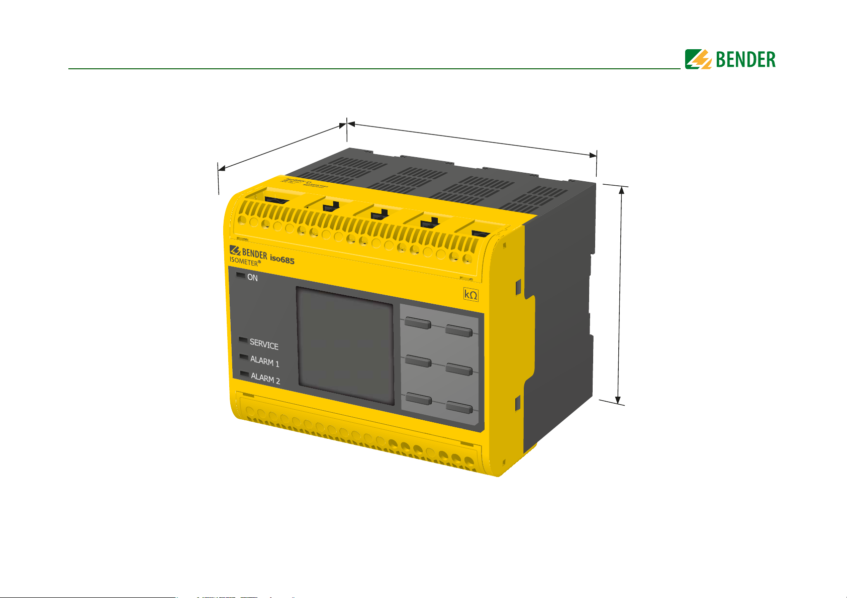
3.1 Dimensions
108 mm
110 mm
mm 39
11
iso685-D-B_D00177_01_M_XXEN/01.2016
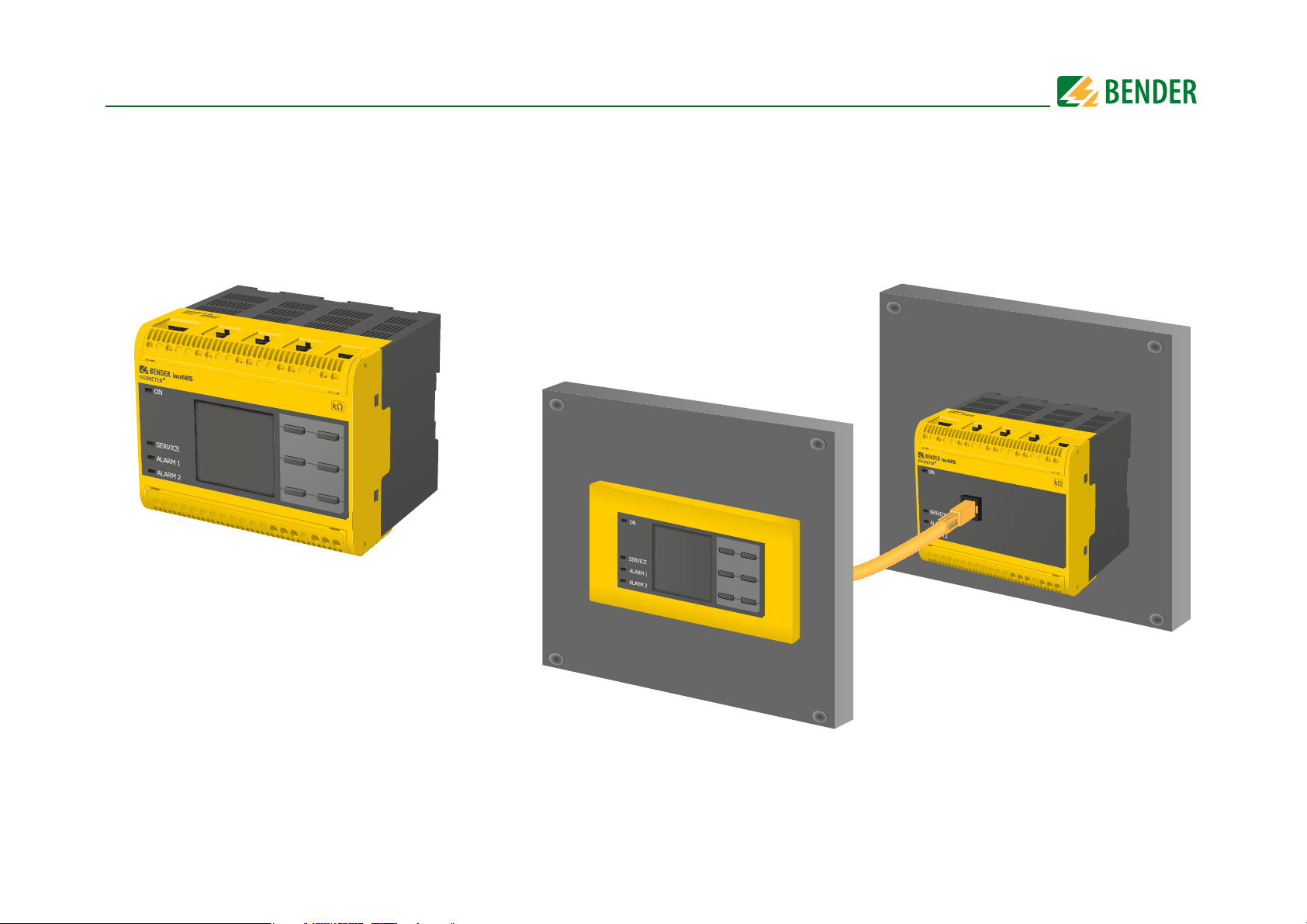
ISOMETER® iso685-D-B
ISOMETER® iso685-S-B with front panel FP200 connected via RJ45 cable
3. Device overview
3.2 Device variants
iso685-D-B:
iso685-S-B: Device version iso685-S-B neither features a display nor operating controls. It can only be used in combination with FP200 and is indirectly operated via
Option "W": Device variants with option W are available in case of extreme climatic and mechanical conditions.
The device version iso685-D-B features a high-resolution graphical LC display and control elements for direct operating of the device functions.
this front panel.
12
iso685-D-B_D00177_01_M_XXEN/01.2016
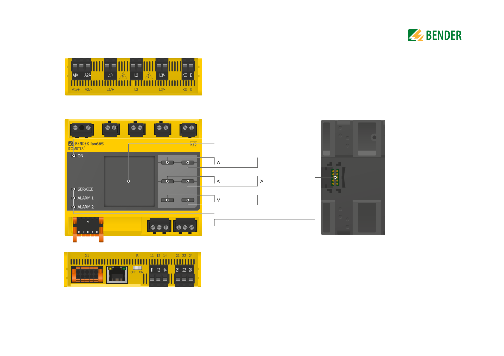
A1/+, A2/- Connection to the power supply voltage U
s
L1/+ Connection to the IT system to be monitored
L2 Connection to the IT system to be monitored
L3/- Connection to the IT system to be monitored
KE, E Connection to PE
To p
Front
Reset
Data
LED display: SERVICE, ALARM 1, ALARM 2
Menu
ESC
Tes t
Info
OK
X3
Optional expansion module for Bender devices
LED display: ON/OFF
Display
ETH
X1 Digital interface
ETH Ethernet interface
R Selectable resistance R
11 12 14 Connector for alarm relay 1
21 22 24 Connector for alarm relay 2
Bottom
3. Device overview
3.3 Connections and panel
13
iso685-D-B_D00177_01_M_XXEN/01.2016
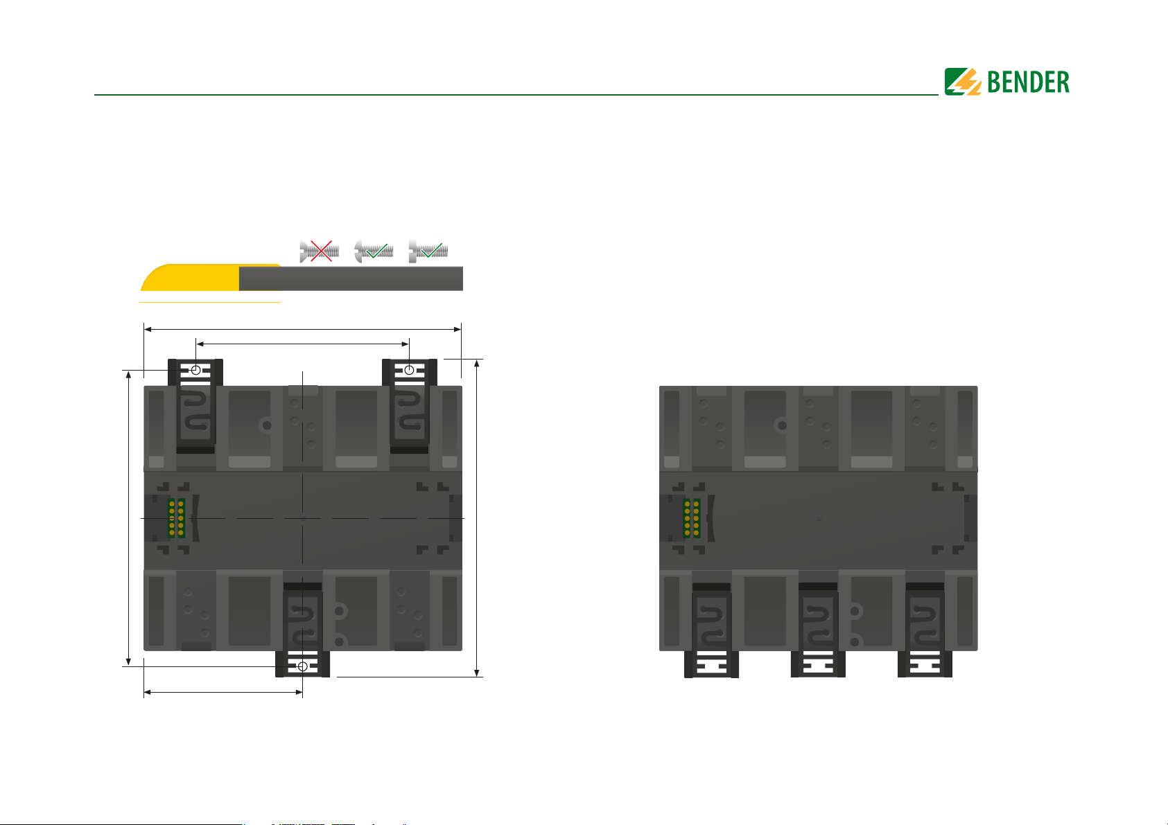
4. Mounting
4.1 Screw mounting
15. Fix the three mounting clips delivered with the device (two of them packed
separately) manually or using a tool, as illustrated below.
16. Drill the mounting holes for the M4 thread according to the dimensioned
drilling template.
17. Fix the ISOMETER® iso685-D-B with three M4 screws.
108 mm
72 mm
4.2 DIN rail mounting
1. Fix the three mounting clips delivered with the device (two of them packed
separately) manually or using a tool, as illustrated below.
2. Fix the ISOMETER® iso685-D-B onto the DIN rail until it snaps into place.
14
100 mm
54 mm
107,3 m m
iso685-D-B_D00177_01_M_XXEN/01.2016
5. Connection
DANGER
DANGER
WARNING
CAUTION
CAUTION
CAUTION
CAUTION
5.1 Connection conditions
Consider the minimum distance to adjacent devices:
lateral 0 mm, top 20 mm, bottom 20 mm.
Risk of electric shock!
Nominal voltages up to 1000 V may be present on the terminals L1/
+ to L3/- which can be lethal. Make sure that the terminal covers
are properly mounted and clicked in before you use the device.
Risk of electric shock!
High voltage is applied to the terminals which can be lethal if directly contacted. If the device is connected via the terminals L1/+,
L2, L3/- to an IT system that is live,‐for operational reasons, terminals KE and E must not be disconnected from th protective earth
conductor (PE).
Warning of insulation monitoring devices that do not work
correctly!
Connect the terminals KE and E individually to the protective earth
conductor PE.
Risk of injury from sharp-edged terminals!
Risk of lacerations.
Touch the enclosure and the terminals with due care.
Ensure disconnection from the IT system!
When insulation or voltage tests are to be carried out, the device
must be isolated from the system for the test period. Otherwise the
device may be damaged.
Risk of property damage due to unprofessional installation!
If more than one insulation monitoring device is connected to a
conductively connected system, the system can be damaged. If
several devices are connected, the device does not function and
does not signal insulation faults. Make sure that only one insulation monitoring device is connected in each conductively connected system.
The ISOMETER® iso685-D-B is suitable for use in coupled systems.
For the necessary parameter setting, refer to “Special functions for
coupled IT systems” from page 38
Risk of property damage due to unprofessional installation!
The connecting lines L1/+, L2, L3/- to the system to be monitored
must be carried out as spur lines. Inadmissible load current can result in damage to property and personal injury. Do not run any
load current through the terminals.
Check proper connection!
Prior to commissioning of the installation, check that the device
has been properly connected and check the device functions. Perform a functional test using an earth fault via a suitable resistance.
Prevent measurement errors!
When the AC system being monitored contains galvanically coupled DC circuits, observe that: an insulation fault can only be detected correctly when the rectifier valves carry a minimum current
of > 10 mA.
For UL applications:
Only use 60/70°C copper lines!
UL and CSA application require the supply voltage to be protected
via 5-A fuses.
15
iso685-D-B_D00177_01_M_XXEN/01.2016
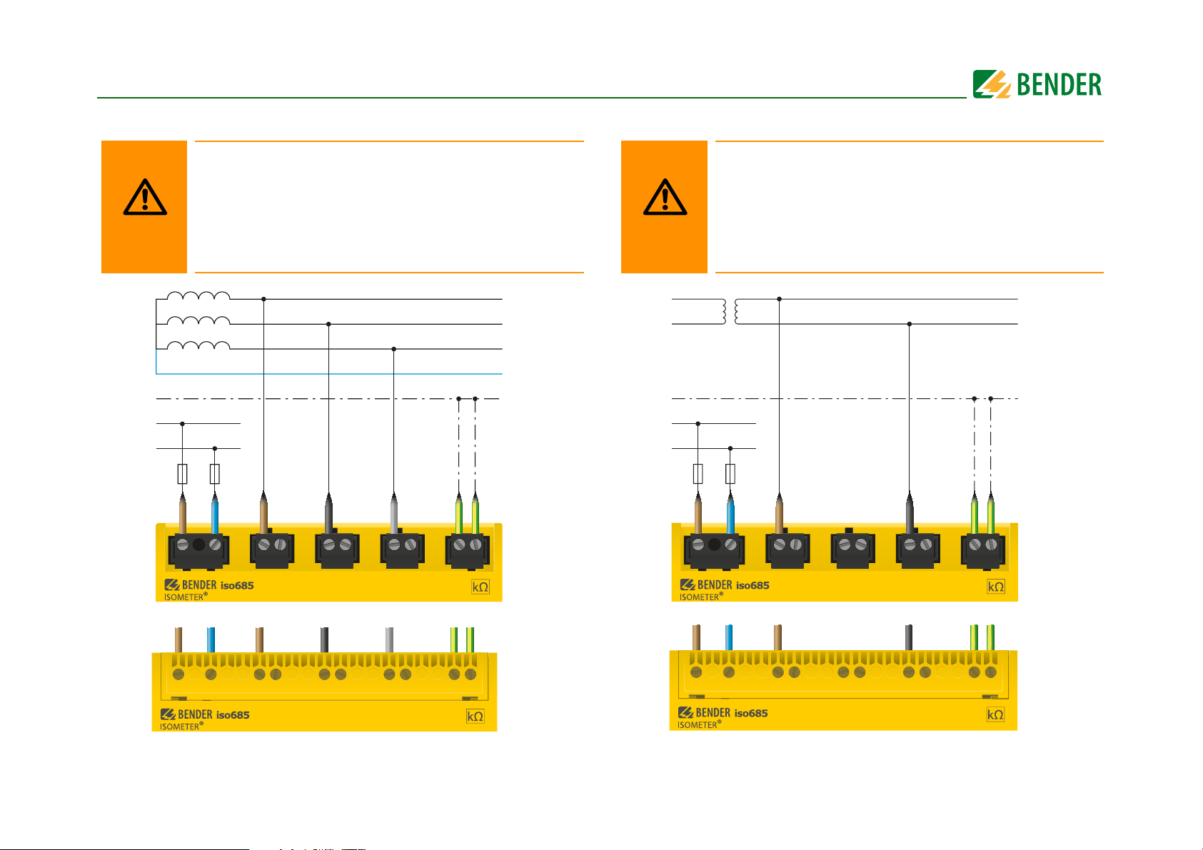
WARNING
L1
L2
L3
N
PE
U
S
6A
U
n
WARNING
L1
L2
PE
U
n
U
S
6A
5. Connection5. Connection
5.2 Connection to a 3(N)AC system/system type 3AC
Risk of injury, fire and damage to property due to a shortcircuit!
According to DIN VDE 0100-430,devices used to protect against a
short-circuit when terminals L1/+, L2 und L3/- are coupled to the IT
system to be monitored can be omitted if the wiring is carried out
in such a manner as to reduce the risk of a short-circuit to a minimum. Ensure short-circuit-proof and earth-fault-proof wiring.
5.3 Connection to an AC system/system type AC
Risk of injury, fire and damage to property due to a shortcircuit!
According to DIN VDE 0100-430,devices used to protect against a
short-circuit when terminals L1/+, L2 und L3/- are coupled to the IT
system to be monitored can be omitted if the wiring is carried out
in such a manner as to reduce the risk of a short-circuit to a minimum. Ensure short-circuit-proof and earth-fault-proof wiring.
Position the terminal cover and click it into place.
16
Position the terminal cover and click it into place.
iso685-D-B_D00177_01_M_XXEN/01.2016
WARNING
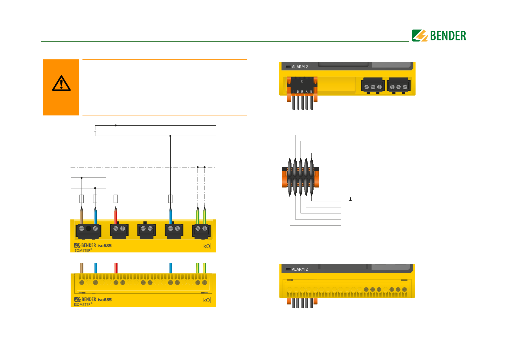
L+
L-
PE
U
S
6A
**
* F 6A for
syste ms
> 690 V
overvoltage category III
U
n
I1
I2
I3
A
B
M+
Q2
Q1
+
Input 1
Input 2
Input 3
RS-485 A
RS-485 B
Ground
Analogue output
Output 2
Output 1
+ 24 V
Electrical overload protection
Auto shut-off in the event of a short
circuit and transients (resettable)
5. Connection5. Connection
5.4 Connection to a DC system/system type DC
Risk of injury, fire and damage to property due to a short-circuit!
According to DIN VDE 0100-430,devices used to protect against a
short-circuit when terminals L1/+, L2 und L3/- are coupled to the IT
system to be monitored can be omitted if the wiring is carried out
in such a manner as to reduce the risk of a short-circuit to a minimum. Ensure short-circuit-proof and earth-fault-proof wiring.
5.5 Connection to the X1 interface
Position the terminal cover and click it into place.
17
Position the terminal cover and click it into place.
iso685-D-B_D00177_01_M_XXEN/01.2016
CAUTION
U
S
6A
CAUTION
CAUTION
+
U
s
5. Connection
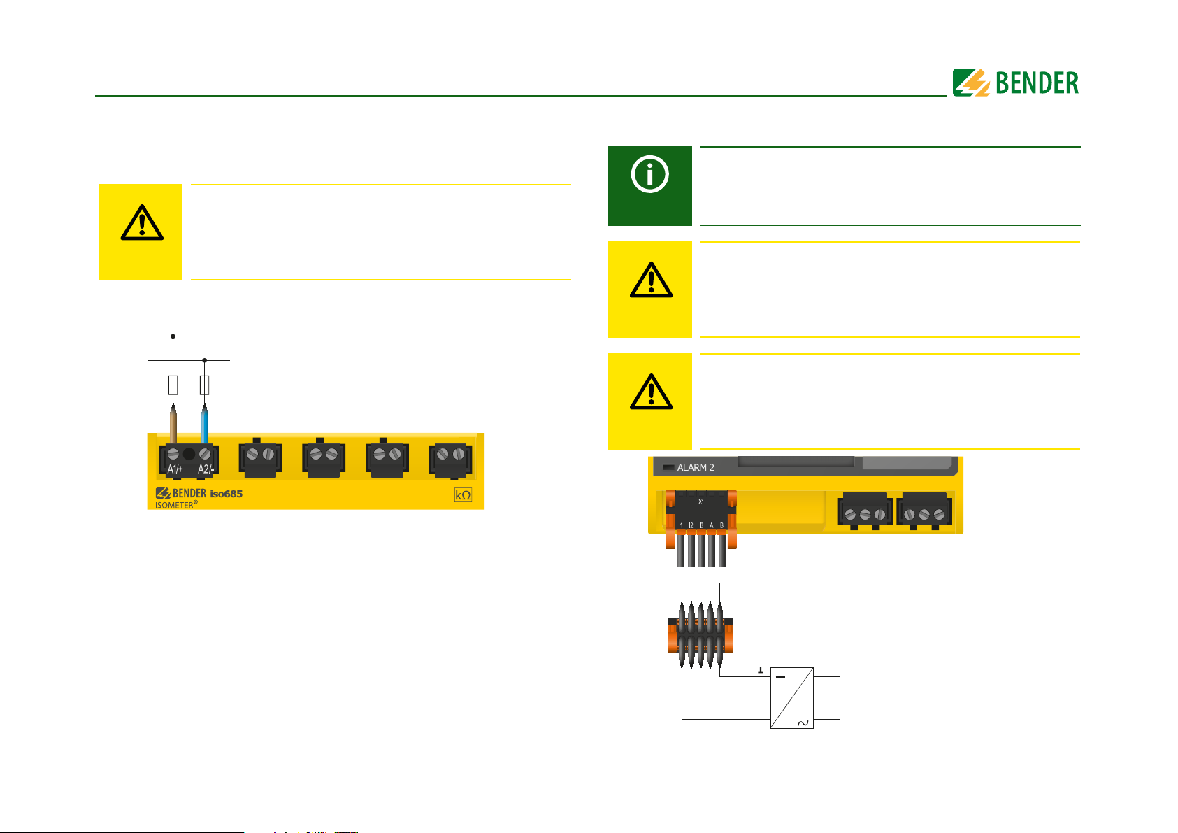
5.6 Connection to the supply voltage
5.6.1 Connection to A1/+, A2/-
Danger of damage to property due to faulty connections!
The device can be damaged if the unit is simultaneously connected
to the supply voltage via the X1 interface, and A1/+, A2/- terminals.
Do not connect the device simultaneously via X1, and A1/+, A2/- to
different supply voltages.
5.6.2 Connection to X1
External Power supply for powering ISOMETER®s via terminal X1
must fulfil immunity and emission standards of the required application. For wiring longer than 1 m the use of a shielded cable is
prescribed.
Danger of damage to property due to faulty connections!
The device can be damaged if the unit is simultaneously connected to
the supply voltage via the X1 interface, and A1/+, A2/- terminals. Do
not connect the device simultaneously via X1, and A1/+, A2/- to different supply voltages.
Danger of damage to property due to incorrect nominal
voltage!
When the device is powered via the X1 interface, the nominal voltage must be 24 V otherwise the unit may be damaged. kann. Only
connect to a nominal voltage of 24 V to the X1 interface.
1
18
iso685-D-B_D00177_01_M_XXEN/01.2016
 Loading...