

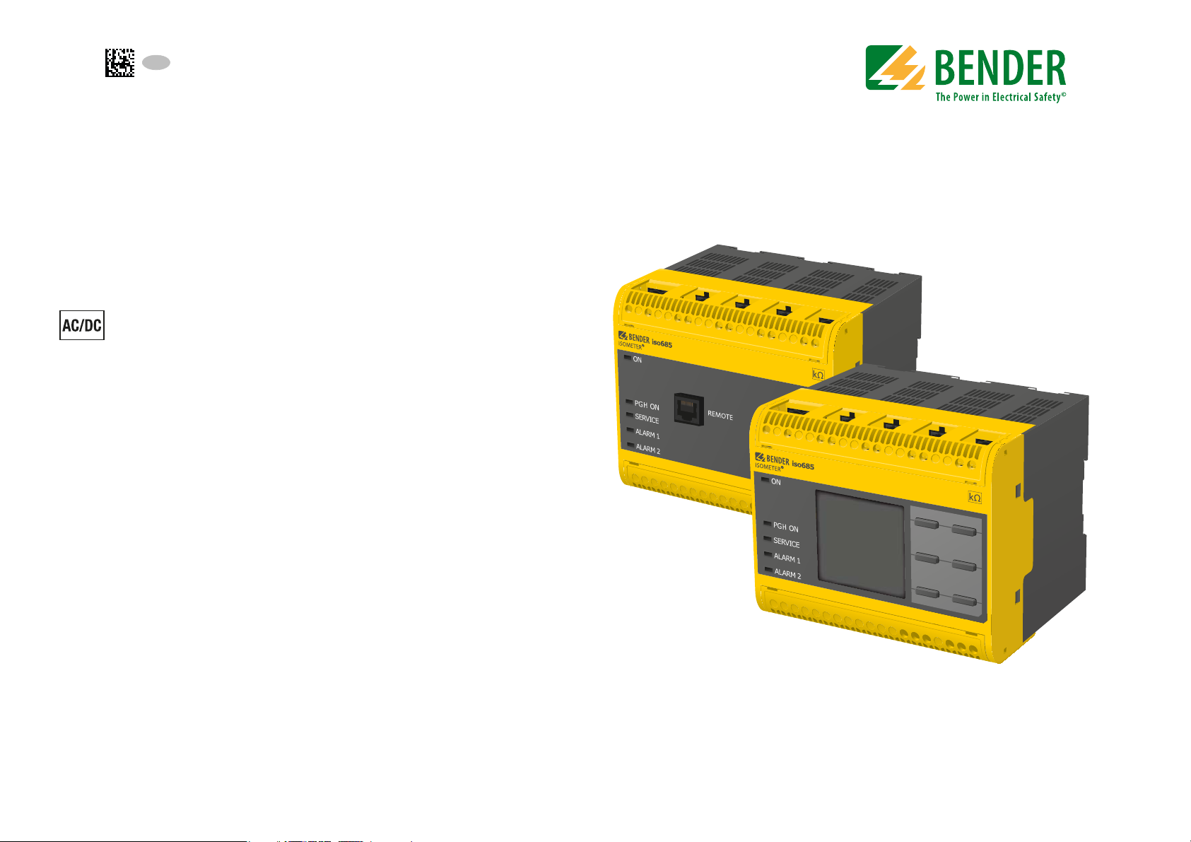
Bender ISOMETER iso685-D-P, ISOMETER iso685W-D-P, ISOMETER iso685-S-P, ISOMETER iso685W-S-P User Manual
Page 1
EN
Manual
ISOMETER® iso685-D-P
iso685W-D-P
iso685-S-P
iso685W-S-P
Insulation Monitoring Device
with integrated locating current injector
for IT AC systems
with galvanically connected rectifiers and inverters
and for IT DC systems
iso685-D-P_D00170_00_M_XXEN/06.2016
Page 2

PLEASE READ THIS MANUAL AND ANY ACCOMPANYING DOCUMENTS CAREFULLY
AND KEEP THEM IN A SECURE PLACE FOR FUTURE REFERENCE.
Bender GmbH & Co. KG
Postfach 1161 • 35301 Gruenberg • Germany
Londorfer Straße 65 • 35305 Gruenberg • Germany
Tel.: +49 6401 807-0
Fax: +49 6401 807-259
E-Mail: [email protected]
Web: www.bender.de
Customer service
Service-Hotline: 0700-BenderHelp (Telephone and Fax)
Carl-Benz-Straße 8 • 35305 Gruenberg • Germany
Tel.:+49 6401 807-760
Fax:+49 6401 807-629
E-Mail:[email protected]
© Bender GmbH & Co. KG
All rights reserved.
Reproduction only with permission
of the publisher.
Subject to change.
Page 3

Table of contents
1. Important information .................................................................... 8
1.1 How to use this manual . . . . . . . . . . . . . . . . . . . . . . . . . . . . . . . . . . . . . . . . . . . . . 8
1.2 Technical support . . . . . . . . . . . . . . . . . . . . . . . . . . . . . . . . . . . . . . . . . . . . . . . . . . 8
1.2.1 First level support . . . . . . . . . . . . . . . . . . . . . . . . . . . . . . . . . . . . . . . . . . . . . . 8
1.2.2 Repair service . . . . . . . . . . . . . . . . . . . . . . . . . . . . . . . . . . . . . . . . . . . . . . . . . . 8
1.2.3 Field service . . . . . . . . . . . . . . . . . . . . . . . . . . . . . . . . . . . . . . . . . . . . . . . . . . . . 9
1.3 Training courses . . . . . . . . . . . . . . . . . . . . . . . . . . . . . . . . . . . . . . . . . . . . . . . . . . . . 9
1.4 Delivery conditions . . . . . . . . . . . . . . . . . . . . . . . . . . . . . . . . . . . . . . . . . . . . . . . . . 9
1.5 Inspection, transport and storage . . . . . . . . . . . . . . . . . . . . . . . . . . . . . . . . . . . 9
1.6 Warranty and liability . . . . . . . . . . . . . . . . . . . . . . . . . . . . . . . . . . . . . . . . . . . . . . . 9
1.7 Disposal. . . . . . . . . . . . . . . . . . . . . . . . . . . . . . . . . . . . . . . . . . . . . . . . . . . . . . . . . . . . 9
2. Safety instructions .......................................................................... 10
2.1 General safety instructions . . . . . . . . . . . . . . . . . . . . . . . . . . . . . . . . . . . . . . . . . 10
2.2 Work activities on electrical installations. . . . . . . . . . . . . . . . . . . . . . . . . . . . 10
2.3 Device-specific safety information . . . . . . . . . . . . . . . . . . . . . . . . . . . . . . . . . 10
2.4 Intended use . . . . . . . . . . . . . . . . . . . . . . . . . . . . . . . . . . . . . . . . . . . . . . . . . . . . . . 11
3. Function ........................................................................................... 11
3.1 Features. . . . . . . . . . . . . . . . . . . . . . . . . . . . . . . . . . . . . . . . . . . . . . . . . . . . . . . . . . . 11
3.1.1 Features ISOMETER® . . . . . . . . . . . . . . . . . . . . . . . . . . . . . . . . . . . . . . . . . . . 11
3.1.2 Features EDS44… . . . . . . . . . . . . . . . . . . . . . . . . . . . . . . . . . . . . . . . . . . . . . 12
3.2 Product description . . . . . . . . . . . . . . . . . . . . . . . . . . . . . . . . . . . . . . . . . . . . . . . 12
3.2.1 General product description . . . . . . . . . . . . . . . . . . . . . . . . . . . . . . . . . . . 12
3.2.2 Special characteristics of ISOMETER® iso685-S-P with front panel 12
3.3 Function description. . . . . . . . . . . . . . . . . . . . . . . . . . . . . . . . . . . . . . . . . . . . . . . 12
3.4 Insulation fault location. . . . . . . . . . . . . . . . . . . . . . . . . . . . . . . . . . . . . . . . . . . . 13
3.5 Interfaces . . . . . . . . . . . . . . . . . . . . . . . . . . . . . . . . . . . . . . . . . . . . . . . . . . . . . . . . . 13
3.6 Self test . . . . . . . . . . . . . . . . . . . . . . . . . . . . . . . . . . . . . . . . . . . . . . . . . . . . . . . . . . . 14
3.7 Compatibility with EDS . . . . . . . . . . . . . . . . . . . . . . . . . . . . . . . . . . . . . . . . . . . . 14
4. Device overview ..............................................................................15
4.1 Dimensions. . . . . . . . . . . . . . . . . . . . . . . . . . . . . . . . . . . . . . . . . . . . . . . . . . . . . . . .15
4.2 Device variants . . . . . . . . . . . . . . . . . . . . . . . . . . . . . . . . . . . . . . . . . . . . . . . . . . . .16
4.3 Connections and panel . . . . . . . . . . . . . . . . . . . . . . . . . . . . . . . . . . . . . . . . . . . .17
4.4 Display elements and device buttons. . . . . . . . . . . . . . . . . . . . . . . . . . . . . . .18
5. Mounting .......................................................................................... 19
5.1 General instructions . . . . . . . . . . . . . . . . . . . . . . . . . . . . . . . . . . . . . . . . . . . . . . .19
5.2 Screw mounting . . . . . . . . . . . . . . . . . . . . . . . . . . . . . . . . . . . . . . . . . . . . . . . . . . . 19
5.3 DIN rail mounting. . . . . . . . . . . . . . . . . . . . . . . . . . . . . . . . . . . . . . . . . . . . . . . . . . 20
6. Connection ....................................................................................... 20
6.1 Connection requirements . . . . . . . . . . . . . . . . . . . . . . . . . . . . . . . . . . . . . . . . . .20
6.2 Connection to a 3(N)AC system. . . . . . . . . . . . . . . . . . . . . . . . . . . . . . . . . . . . .22
6.3 Connection to an AC system . . . . . . . . . . . . . . . . . . . . . . . . . . . . . . . . . . . . . . .22
6.4 Connection to a DC system. . . . . . . . . . . . . . . . . . . . . . . . . . . . . . . . . . . . . . . . .23
6.5 Connection to the X1 interface . . . . . . . . . . . . . . . . . . . . . . . . . . . . . . . . . . . . .23
6.6 Connection to the supply voltage . . . . . . . . . . . . . . . . . . . . . . . . . . . . . . . . . .24
6.7 Connection to the Ethernet interface . . . . . . . . . . . . . . . . . . . . . . . . . . . . . . .24
6.8 Connection to the relay 1 interface (11 12 14) . . . . . . . . . . . . . . . . . . . . . . 25
6.9 Connection to the relay 2 interface (21 22 24) . . . . . . . . . . . . . . . . . . . . . . 25
6.10 Connection to the BB bus . . . . . . . . . . . . . . . . . . . . . . . . . . . . . . . . . . . . . . . . .26
6.11 Connecting the EDS to the ISOMETER® . . . . . . . . . . . . . . . . . . . . . . . . . . . .26
6.11.1 Connection example ISOMETER® to EDS . . . . . . . . . . . . . . . . . . . . . . .27
6.11.2 Connection to a 3(N)AC system . . . . . . . . . . . . . . . . . . . . . . . . . . . . . . . .28
6.11.3 Connection to an AC system . . . . . . . . . . . . . . . . . . . . . . . . . . . . . . . . . . .29
6.11.4 Connection to a DC system . . . . . . . . . . . . . . . . . . . . . . . . . . . . . . . . . . . .30
6.11.5 System structure . . . . . . . . . . . . . . . . . . . . . . . . . . . . . . . . . . . . . . . . . . . . . .31
3
iso685-D-P_D00170_00_M_XXDE/04.2016
Page 4

Table of contents
7. Commissioning ............................................................................... 32
7.1 General initial commissioning process. . . . . . . . . . . . . . . . . . . . . . . . . . . . . . 32
7.2 Initial commissioning . . . . . . . . . . . . . . . . . . . . . . . . . . . . . . . . . . . . . . . . . . . . . . 33
7.2.1 Set language . . . . . . . . . . . . . . . . . . . . . . . . . . . . . . . . . . . . . . . . . . . . . . . . . . 33
7.2.2 Set time and date . . . . . . . . . . . . . . . . . . . . . . . . . . . . . . . . . . . . . . . . . . . . . 33
7.2.3 Setting system type . . . . . . . . . . . . . . . . . . . . . . . . . . . . . . . . . . . . . . . . . . . 33
7.2.4 Set profile . . . . . . . . . . . . . . . . . . . . . . . . . . . . . . . . . . . . . . . . . . . . . . . . . . . . . 33
7.2.5 Setting EDS mode . . . . . . . . . . . . . . . . . . . . . . . . . . . . . . . . . . . . . . . . . . . . . 33
7.2.6 Setting EDS current . . . . . . . . . . . . . . . . . . . . . . . . . . . . . . . . . . . . . . . . . . . 34
7.2.7 Set response value Ran1 for alarm 1 . . . . . . . . . . . . . . . . . . . . . . . . . . . . 34
7.2.8 Set response value Ran2 for alarm 2 . . . . . . . . . . . . . . . . . . . . . . . . . . . . 34
7.3 Recommissioning . . . . . . . . . . . . . . . . . . . . . . . . . . . . . . . . . . . . . . . . . . . . . . . . .34
7.4 Commissioning EDS . . . . . . . . . . . . . . . . . . . . . . . . . . . . . . . . . . . . . . . . . . . . . . . 35
8. Display .............................................................................................. 36
8.1 Standard display. . . . . . . . . . . . . . . . . . . . . . . . . . . . . . . . . . . . . . . . . . . . . . . . . . . 36
8.2 Fault display (active) . . . . . . . . . . . . . . . . . . . . . . . . . . . . . . . . . . . . . . . . . . . . . . . 36
8.3 Fault display (inactive) . . . . . . . . . . . . . . . . . . . . . . . . . . . . . . . . . . . . . . . . . . . . . 37
8.4 Acknowledging a fault message . . . . . . . . . . . . . . . . . . . . . . . . . . . . . . . . . . . 38
8.5 Data - isoGraph. . . . . . . . . . . . . . . . . . . . . . . . . . . . . . . . . . . . . . . . . . . . . . . . . . . . 38
8.6 History memory . . . . . . . . . . . . . . . . . . . . . . . . . . . . . . . . . . . . . . . . . . . . . . . . . . . 39
8.7 Insulation fault location. . . . . . . . . . . . . . . . . . . . . . . . . . . . . . . . . . . . . . . . . . . . 39
8.8 Initial measurement . . . . . . . . . . . . . . . . . . . . . . . . . . . . . . . . . . . . . . . . . . . . . . . 40
9. Menu ................................................................................................. 41
9.1 Menu structure . . . . . . . . . . . . . . . . . . . . . . . . . . . . . . . . . . . . . . . . . . . . . . . . . . . . 41
9.2 Operating and navigating . . . . . . . . . . . . . . . . . . . . . . . . . . . . . . . . . . . . . . . . . 42
9.2.1 Easy operation . . . . . . . . . . . . . . . . . . . . . . . . . . . . . . . . . . . . . . . . . . . . . . . . 42
9.2.2 Multiple selection in the device menu . . . . . . . . . . . . . . . . . . . . . . . . . . 43
10. Settings........................................................................................... 44
10.1 Settings in the device menu . . . . . . . . . . . . . . . . . . . . . . . . . . . . . . . . . . . . . .44
10.1 1. Alarm settings . . . . . . . . . . . . . . . . . . . . . . . . . . . . . . . . . . . . . . . . . . . 44
10.1 1.1 Insulation alarm . . . . . . . . . . . . . . . . . . . . . . . . . . . . . . . . . . . . . . . 44
10.1 1.1.1 Alarm 1 . . . . . . . . . . . . . . . . . . . . . . . . . . . . . . . . . . . . . . . . . . . . . 44
10.1 1.1.2 Alarm 2 . . . . . . . . . . . . . . . . . . . . . . . . . . . . . . . . . . . . . . . . . . . . . 44
10.1 1.1.3 Fault memory . . . . . . . . . . . . . . . . . . . . . . . . . . . . . . . . . . . . . . 44
10.1 1.2 DC alarm . . . . . . . . . . . . . . . . . . . . . . . . . . . . . . . . . . . . . . . . . . . . . . 44
10.1 1.2.1 Alarm . . . . . . . . . . . . . . . . . . . . . . . . . . . . . . . . . . . . . . . . . . . . . . 44
10.1 1.2.2 U(DC-E). . . . . . . . . . . . . . . . . . . . . . . . . . . . . . . . . . . . . . . . . . . . . 44
10.1 1.3 Profile . . . . . . . . . . . . . . . . . . . . . . . . . . . . . . . . . . . . . . . . . . . . . . . . . 45
10.1 1.4 System type . . . . . . . . . . . . . . . . . . . . . . . . . . . . . . . . . . . . . . . . . . . 45
10.1 1.5 ISOnet . . . . . . . . . . . . . . . . . . . . . . . . . . . . . . . . . . . . . . . . . . . . . . . . . 45
10.1 1.5.1 ISOnet. . . . . . . . . . . . . . . . . . . . . . . . . . . . . . . . . . . . . . . . . . . . . . 45
10.1 1.5.2 Number of devices. . . . . . . . . . . . . . . . . . . . . . . . . . . . . . . . . . 45
10.1 1.6 Device. . . . . . . . . . . . . . . . . . . . . . . . . . . . . . . . . . . . . . . . . . . . . . . . . 45
10.1 1.7 T(Start) . . . . . . . . . . . . . . . . . . . . . . . . . . . . . . . . . . . . . . . . . . . . . . . . 45
10.1 1.8 Coupling monitoring. . . . . . . . . . . . . . . . . . . . . . . . . . . . . . . . . . . 45
10.1 1.9 Inputs . . . . . . . . . . . . . . . . . . . . . . . . . . . . . . . . . . . . . . . . . . . . . . . . . 46
10.1 1.9.1 Digital 1 . . . . . . . . . . . . . . . . . . . . . . . . . . . . . . . . . . . . . . . . . . . . 46
10.1 1.9.1.1 Mode. . . . . . . . . . . . . . . . . . . . . . . . . . . . . . . . . . . . . . . . . . . . 46
10.1 1.9.1.2 t(on). . . . . . . . . . . . . . . . . . . . . . . . . . . . . . . . . . . . . . . . . . . . . 46
10.1 1.9.1.3 t(off) . . . . . . . . . . . . . . . . . . . . . . . . . . . . . . . . . . . . . . . . . . . . 46
10.1 1.9.1.4 Function . . . . . . . . . . . . . . . . . . . . . . . . . . . . . . . . . . . . . . . . 47
10.1 1.9.2 Digital 2 . . . . . . . . . . . . . . . . . . . . . . . . . . . . . . . . . . . . . . . . . . . . 47
10.1 1.9.3 Digital 3 . . . . . . . . . . . . . . . . . . . . . . . . . . . . . . . . . . . . . . . . . . . . 47
10.1 1.10 Outputs . . . . . . . . . . . . . . . . . . . . . . . . . . . . . . . . . . . . . . . . . . . . . . 47
10.1 1.10.1 Relay 1 . . . . . . . . . . . . . . . . . . . . . . . . . . . . . . . . . . . . . . . . . . . . 47
10.1 1.10.1.1 TEST . . . . . . . . . . . . . . . . . . . . . . . . . . . . . . . . . . . . . . . . . . . 47
10.1 1.10.1.2 Relay operating mode . . . . . . . . . . . . . . . . . . . . . . . . . . 47
10.1 1.10.1.3 Function 1 . . . . . . . . . . . . . . . . . . . . . . . . . . . . . . . . . . . . . 47
10.1 1.10.1.4 Function 2 . . . . . . . . . . . . . . . . . . . . . . . . . . . . . . . . . . . . . 48
10.1 1.10.1.5 Function 3 . . . . . . . . . . . . . . . . . . . . . . . . . . . . . . . . . . . . . 48
10.1 1.10.2 Relay 2 . . . . . . . . . . . . . . . . . . . . . . . . . . . . . . . . . . . . . . . . . . . . 48
10.1 1.10.3 Digital 1 . . . . . . . . . . . . . . . . . . . . . . . . . . . . . . . . . . . . . . . . . . . 48
10.1 1.10.3.1 TEST . . . . . . . . . . . . . . . . . . . . . . . . . . . . . . . . . . . . . . . . . . . 49
10.1 1.10.3.2 Mode . . . . . . . . . . . . . . . . . . . . . . . . . . . . . . . . . . . . . . . . . . 49
10.1 1.10.3.3 Function 1 . . . . . . . . . . . . . . . . . . . . . . . . . . . . . . . . . . . . . 49
10.1 1.10.3.4 Function 2 . . . . . . . . . . . . . . . . . . . . . . . . . . . . . . . . . . . . . 49
4
iso685-D-P_D00170_00_M_XXDE/04.2016
Page 5

Table of contents
10.1 1.10.3.5 Function 3 . . . . . . . . . . . . . . . . . . . . . . . . . . . . . . . . . . . . . 49
10.1 1.10.4 Digital 2. . . . . . . . . . . . . . . . . . . . . . . . . . . . . . . . . . . . . . . . . . . 49
10.1 1.10.5 Buzzer . . . . . . . . . . . . . . . . . . . . . . . . . . . . . . . . . . . . . . . . . . . . 49
10.1 1.10.5.1 TEST . . . . . . . . . . . . . . . . . . . . . . . . . . . . . . . . . . . . . . . . . . . 49
10.1 1.10.5.2 Function 1 . . . . . . . . . . . . . . . . . . . . . . . . . . . . . . . . . . . . . 49
10.1 1.10.5.3 Function 2 . . . . . . . . . . . . . . . . . . . . . . . . . . . . . . . . . . . . . 49
10.1 1.10.5.4 Function 3 . . . . . . . . . . . . . . . . . . . . . . . . . . . . . . . . . . . . . 49
10.1 1.10.6 Analogue . . . . . . . . . . . . . . . . . . . . . . . . . . . . . . . . . . . . . . . . . 50
10.1 1.10.6.1 Mode . . . . . . . . . . . . . . . . . . . . . . . . . . . . . . . . . . . . . . . . . . 50
10.1 1.10.6.2 Midscale . . . . . . . . . . . . . . . . . . . . . . . . . . . . . . . . . . . . . . . 50
10.1 1.10.6.3 TEST . . . . . . . . . . . . . . . . . . . . . . . . . . . . . . . . . . . . . . . . . . . 51
10.1 1.10.6.4 Function . . . . . . . . . . . . . . . . . . . . . . . . . . . . . . . . . . . . . . . 51
10.1 2. EDS (insulation fault location) . . . . . . . . . . . . . . . . . . . . . . . . . . . . . 51
10.1 2.1 General . . . . . . . . . . . . . . . . . . . . . . . . . . . . . . . . . . . . . . . . . . . . . . . 51
10.1 2.1.1 Current. . . . . . . . . . . . . . . . . . . . . . . . . . . . . . . . . . . . . . . . . . . . . 51
10.1 2.1.2 Mode . . . . . . . . . . . . . . . . . . . . . . . . . . . . . . . . . . . . . . . . . . . . . . 52
10.1 2.1.3 Using a portable EDS . . . . . . . . . . . . . . . . . . . . . . . . . . . . . . . 52
10.1 2.2 Scanning channels. . . . . . . . . . . . . . . . . . . . . . . . . . . . . . . . . . . . . 52
10.1 2.3 Activating channels. . . . . . . . . . . . . . . . . . . . . . . . . . . . . . . . . . . . 53
10.1 2.4 Group settings . . . . . . . . . . . . . . . . . . . . . . . . . . . . . . . . . . . . . . . . 53
10.1 2.4.1 Channel . . . . . . . . . . . . . . . . . . . . . . . . . . . . . . . . . . . . . . . . . . . . 53
10.1 2.4.1.1 Current transformer (CT) . . . . . . . . . . . . . . . . . . . . . . . . . 53
10.1 2.4.1.2 CT monitoring. . . . . . . . . . . . . . . . . . . . . . . . . . . . . . . . . . . 53
10.1 2.4.1.3 I∆L Response value . . . . . . . . . . . . . . . . . . . . . . . . . . . . . . 54
10.1 2.4.1.4 I∆n Response value . . . . . . . . . . . . . . . . . . . . . . . . . . . . . . 54
10.1 2.4.2 Outputs . . . . . . . . . . . . . . . . . . . . . . . . . . . . . . . . . . . . . . . . . . . . 54
10.1 2.4.2.1 Relays . . . . . . . . . . . . . . . . . . . . . . . . . . . . . . . . . . . . . . . . . . . 54
10.1 2.4.2.2 Buzzer . . . . . . . . . . . . . . . . . . . . . . . . . . . . . . . . . . . . . . . . . . 55
10.1 2.4.2.3 Digital output . . . . . . . . . . . . . . . . . . . . . . . . . . . . . . . . . . . 55
10.1 2.4.2.4 Function 1 . . . . . . . . . . . . . . . . . . . . . . . . . . . . . . . . . . . . . . 56
10.1 2.4.2.5 Function 2 . . . . . . . . . . . . . . . . . . . . . . . . . . . . . . . . . . . . . . 56
10.1 2.4.2.6 Function 3 . . . . . . . . . . . . . . . . . . . . . . . . . . . . . . . . . . . . . . 56
10.1 2.4.3 Dig. input . . . . . . . . . . . . . . . . . . . . . . . . . . . . . . . . . . . . . . . . . . 56
10.1 2.4.3.1 Mode . . . . . . . . . . . . . . . . . . . . . . . . . . . . . . . . . . . . . . . . . . . 56
10.1 2.4.3.2 t(on) . . . . . . . . . . . . . . . . . . . . . . . . . . . . . . . . . . . . . . . . . . . . 56
10.1 2.4.3.3 t(off) . . . . . . . . . . . . . . . . . . . . . . . . . . . . . . . . . . . . . . . . . . . . 56
10.1 2.4.3.4 Function . . . . . . . . . . . . . . . . . . . . . . . . . . . . . . . . . . . . . . . . 56
10.1 2.4.4 Device settings . . . . . . . . . . . . . . . . . . . . . . . . . . . . . . . . . . . . . 56
10.1 2.4.4.1 System type . . . . . . . . . . . . . . . . . . . . . . . . . . . . . . . . . . . . . 57
10.1 2.4.4.2 Frequency. . . . . . . . . . . . . . . . . . . . . . . . . . . . . . . . . . . . . . . 57
10.1 2.4.4.3 Trigger . . . . . . . . . . . . . . . . . . . . . . . . . . . . . . . . . . . . . . . . . . 57
10.1 2.4.4.4 Fault memory . . . . . . . . . . . . . . . . . . . . . . . . . . . . . . . . . . . 57
10.1 2.5 Channel . . . . . . . . . . . . . . . . . . . . . . . . . . . . . . . . . . . . . . . . . . . . . . . 57
10.1 2.5.1 Name . . . . . . . . . . . . . . . . . . . . . . . . . . . . . . . . . . . . . . . . . . . . . . 57
10.1 2.5.2 Current transformer monitoring . . . . . . . . . . . . . . . . . . . . . 58
10.1 2.5.3 Response value I∆L . . . . . . . . . . . . . . . . . . . . . . . . . . . . . . . . . 58
10.1 2.5.4 Response value I∆n . . . . . . . . . . . . . . . . . . . . . . . . . . . . . . . . . 58
10.1 2.6 Outputs . . . . . . . . . . . . . . . . . . . . . . . . . . . . . . . . . . . . . . . . . . . . . . . 58
10.1 2.6.1 Relays . . . . . . . . . . . . . . . . . . . . . . . . . . . . . . . . . . . . . . . . . . . . . . 58
10.1 2.6.1.1 TEST. . . . . . . . . . . . . . . . . . . . . . . . . . . . . . . . . . . . . . . . . . . . . 58
10.1 2.6.1.2 Operating mode . . . . . . . . . . . . . . . . . . . . . . . . . . . . . . . . . 58
10.1 2.6.1.3 Function 1 . . . . . . . . . . . . . . . . . . . . . . . . . . . . . . . . . . . . . . . 58
10.1 2.6.1.4 Function 2 . . . . . . . . . . . . . . . . . . . . . . . . . . . . . . . . . . . . . . . 58
10.1 2.6.1.5 Function 3 . . . . . . . . . . . . . . . . . . . . . . . . . . . . . . . . . . . . . . . 58
10.1 2.6.2 Buzzer . . . . . . . . . . . . . . . . . . . . . . . . . . . . . . . . . . . . . . . . . . . . . . 58
10.1 2.6.2.1 TEST. . . . . . . . . . . . . . . . . . . . . . . . . . . . . . . . . . . . . . . . . . . . . 58
10.1 2.6.2.2 Function 1 . . . . . . . . . . . . . . . . . . . . . . . . . . . . . . . . . . . . . . . 58
10.1 2.6.2.3 Function 2 . . . . . . . . . . . . . . . . . . . . . . . . . . . . . . . . . . . . . . . 58
10.1 2.6.2.4 Function 3 . . . . . . . . . . . . . . . . . . . . . . . . . . . . . . . . . . . . . . . 58
10.1 2.6.3 Digital output . . . . . . . . . . . . . . . . . . . . . . . . . . . . . . . . . . . . . . 58
10.1 2.6.3.1 TEST. . . . . . . . . . . . . . . . . . . . . . . . . . . . . . . . . . . . . . . . . . . . . 58
10.1 2.6.3.2 Function 1 . . . . . . . . . . . . . . . . . . . . . . . . . . . . . . . . . . . . . . . 58
10.1 2.6.3.3 Function 2 . . . . . . . . . . . . . . . . . . . . . . . . . . . . . . . . . . . . . . . 58
10.1 2.6.3.4 Function 3 . . . . . . . . . . . . . . . . . . . . . . . . . . . . . . . . . . . . . . . 58
10.1 2.7 Inputs . . . . . . . . . . . . . . . . . . . . . . . . . . . . . . . . . . . . . . . . . . . . . . . . . 58
10.1 2.7.1 Mode. . . . . . . . . . . . . . . . . . . . . . . . . . . . . . . . . . . . . . . . . . . . . . . 58
10.1 2.7.2 t(on). . . . . . . . . . . . . . . . . . . . . . . . . . . . . . . . . . . . . . . . . . . . . . . . 58
10.1 2.7.3 t(off). . . . . . . . . . . . . . . . . . . . . . . . . . . . . . . . . . . . . . . . . . . . . . . . 58
10.1 2.7.4 Function. . . . . . . . . . . . . . . . . . . . . . . . . . . . . . . . . . . . . . . . . . . . 58
10.1 2.8 Device. . . . . . . . . . . . . . . . . . . . . . . . . . . . . . . . . . . . . . . . . . . . . . . . . 59
10.1 2.8.1 Trigger . . . . . . . . . . . . . . . . . . . . . . . . . . . . . . . . . . . . . . . . . . . . . 59
10.1 2.8.2 Fault memory . . . . . . . . . . . . . . . . . . . . . . . . . . . . . . . . . . . . . . 59
10.1 2.9 Service . . . . . . . . . . . . . . . . . . . . . . . . . . . . . . . . . . . . . . . . . . . . . . . . 59
10.1 3. Data measured values . . . . . . . . . . . . . . . . . . . . . . . . . . . . . . . . . . . . . 59
10.1 4. Control . . . . . . . . . . . . . . . . . . . . . . . . . . . . . . . . . . . . . . . . . . . . . . . . . . .59
10.1 5. History . . . . . . . . . . . . . . . . . . . . . . . . . . . . . . . . . . . . . . . . . . . . . . . . . . . 59
10.1 6. Device settings . . . . . . . . . . . . . . . . . . . . . . . . . . . . . . . . . . . . . . . . . . .59
10.1 6.1 Language. . . . . . . . . . . . . . . . . . . . . . . . . . . . . . . . . . . . . . . . . . . . . . 59
10.1 6.2 Clock . . . . . . . . . . . . . . . . . . . . . . . . . . . . . . . . . . . . . . . . . . . . . . . . . . 60
10.1 6.2.1 Time . . . . . . . . . . . . . . . . . . . . . . . . . . . . . . . . . . . . . . . . . . . . . . . 60
5
iso685-D-P_D00170_00_M_XXDE/04.2016
Page 6

Table of contents
10.1 6.2.2 Format (time). . . . . . . . . . . . . . . . . . . . . . . . . . . . . . . . . . . . . . . 60
10.1 6.2.3 Summer time. . . . . . . . . . . . . . . . . . . . . . . . . . . . . . . . . . . . . . . 60
10.1 6.2.4 Date . . . . . . . . . . . . . . . . . . . . . . . . . . . . . . . . . . . . . . . . . . . . . . . 60
10.1 6.2.5 Format (date). . . . . . . . . . . . . . . . . . . . . . . . . . . . . . . . . . . . . . . 60
10.1 6.2.6 NTP . . . . . . . . . . . . . . . . . . . . . . . . . . . . . . . . . . . . . . . . . . . . . . . . 60
10.1 6.2.7 NTP server. . . . . . . . . . . . . . . . . . . . . . . . . . . . . . . . . . . . . . . . . . 60
10.1 6.2.8 UTC . . . . . . . . . . . . . . . . . . . . . . . . . . . . . . . . . . . . . . . . . . . . . . . . 60
10.1 6.3 Interface . . . . . . . . . . . . . . . . . . . . . . . . . . . . . . . . . . . . . . . . . . . . . . 60
10.1 6.3.1 Write access . . . . . . . . . . . . . . . . . . . . . . . . . . . . . . . . . . . . . . . . 61
10.1 6.3.2 Ethernet. . . . . . . . . . . . . . . . . . . . . . . . . . . . . . . . . . . . . . . . . . . . 61
10.1 6.3.2.1 DHCP . . . . . . . . . . . . . . . . . . . . . . . . . . . . . . . . . . . . . . . . . . . 61
10.1 6.3.2.2 IP . . . . . . . . . . . . . . . . . . . . . . . . . . . . . . . . . . . . . . . . . . . . . . . 61
10.1 6.3.2.3 SN . . . . . . . . . . . . . . . . . . . . . . . . . . . . . . . . . . . . . . . . . . . . . . 61
10.1 6.3.2.4 Std. GW . . . . . . . . . . . . . . . . . . . . . . . . . . . . . . . . . . . . . . . . . 61
10.1 6.3.2.5 DNS server . . . . . . . . . . . . . . . . . . . . . . . . . . . . . . . . . . . . . . 61
10.1 6.3.2.6 Domain . . . . . . . . . . . . . . . . . . . . . . . . . . . . . . . . . . . . . . . . . 61
10.1 6.3.3 BCOM . . . . . . . . . . . . . . . . . . . . . . . . . . . . . . . . . . . . . . . . . . . . . . 61
10.1 6.3.3.1 System name. . . . . . . . . . . . . . . . . . . . . . . . . . . . . . . . . . . . 61
10.1 6.3.3.2 Subsystem . . . . . . . . . . . . . . . . . . . . . . . . . . . . . . . . . . . . . . 61
10.1 6.3.3.3 Device address . . . . . . . . . . . . . . . . . . . . . . . . . . . . . . . . . . 61
10.1 6.3.3.4 Timeout. . . . . . . . . . . . . . . . . . . . . . . . . . . . . . . . . . . . . . . . . 61
10.1 6.3.3.5 TTL for subscription . . . . . . . . . . . . . . . . . . . . . . . . . . . . . 61
10.1 6.3.4 Modbus TCP. . . . . . . . . . . . . . . . . . . . . . . . . . . . . . . . . . . . . . . . 61
10.1 6.3.4.1 Port 502. . . . . . . . . . . . . . . . . . . . . . . . . . . . . . . . . . . . . . . . . 62
10.1 6.3.5 BS bus. . . . . . . . . . . . . . . . . . . . . . . . . . . . . . . . . . . . . . . . . . . . . . 62
10.1 6.3.5.1 Address . . . . . . . . . . . . . . . . . . . . . . . . . . . . . . . . . . . . . . . . . 62
10.1 6.4 Display . . . . . . . . . . . . . . . . . . . . . . . . . . . . . . . . . . . . . . . . . . . . . . . . 62
10.1 6.4.1 Brightness. . . . . . . . . . . . . . . . . . . . . . . . . . . . . . . . . . . . . . . . . . 62
10.1 6.5 Password . . . . . . . . . . . . . . . . . . . . . . . . . . . . . . . . . . . . . . . . . . . . . . 62
10.1 6.5.1 Password. . . . . . . . . . . . . . . . . . . . . . . . . . . . . . . . . . . . . . . . . . . 62
10.1 6.5.2 Status . . . . . . . . . . . . . . . . . . . . . . . . . . . . . . . . . . . . . . . . . . . . . . 62
10.1 6.6 Commissioning . . . . . . . . . . . . . . . . . . . . . . . . . . . . . . . . . . . . . . . . 62
10.1 6.7 Data backup. . . . . . . . . . . . . . . . . . . . . . . . . . . . . . . . . . . . . . . . . . . 62
10.1 6.8 Service . . . . . . . . . . . . . . . . . . . . . . . . . . . . . . . . . . . . . . . . . . . . . . . . 62
10.1 7. Info . . . . . . . . . . . . . . . . . . . . . . . . . . . . . . . . . . . . . . . . . . . . . . . . . . . . . . 62
10.2 Factory settings . . . . . . . . . . . . . . . . . . . . . . . . . . . . . . . . . . . . . . . . . . . . . . . . . . 63
11. Device communication ................................................................64
11.1 Ethernet interface . . . . . . . . . . . . . . . . . . . . . . . . . . . . . . . . . . . . . . . . . . . . . . . .64
11.2 BCOM . . . . . . . . . . . . . . . . . . . . . . . . . . . . . . . . . . . . . . . . . . . . . . . . . . . . . . . . . . . .64
11.3 Modbus TCP. . . . . . . . . . . . . . . . . . . . . . . . . . . . . . . . . . . . . . . . . . . . . . . . . . . . . .64
11.4 Web server . . . . . . . . . . . . . . . . . . . . . . . . . . . . . . . . . . . . . . . . . . . . . . . . . . . . . . .65
11.5 BS bus. . . . . . . . . . . . . . . . . . . . . . . . . . . . . . . . . . . . . . . . . . . . . . . . . . . . . . . . . . . .68
12. Insulation fault location ..............................................................69
12.1 General description. . . . . . . . . . . . . . . . . . . . . . . . . . . . . . . . . . . . . . . . . . . . . . . 69
12.2 Required settings for insulation fault location . . . . . . . . . . . . . . . . . . . . . 69
12.3 Indication on the display. . . . . . . . . . . . . . . . . . . . . . . . . . . . . . . . . . . . . . . . . .69
12.4 Starting and stopping the insulation fault location. . . . . . . . . . . . . . . . .69
13. Special functions for coupled IT systems .................................70
13.1 Particularities when monitoring coupled IT systems . . . . . . . . . . . . . . . 70
13.2 System isolation via digital input with two coupled systems . . . . . . .70
13.3 System isolation via ISOnet . . . . . . . . . . . . . . . . . . . . . . . . . . . . . . . . . . . . . . .71
14. Device profiles ............................................................................... 73
15. Diagrams ........................................................................................ 74
15.1 Response time profile power circuits . . . . . . . . . . . . . . . . . . . . . . . . . . . . . . 74
15.2 Response time profile control circuits . . . . . . . . . . . . . . . . . . . . . . . . . . . . .74
15.3 Response time profile generator . . . . . . . . . . . . . . . . . . . . . . . . . . . . . . . . . .75
15.4 Response time profile high capacitance . . . . . . . . . . . . . . . . . . . . . . . . . . .75
15.5 Response time profile inverter > 10 Hz . . . . . . . . . . . . . . . . . . . . . . . . . . . .76
15.6 Response time profile inverter < 10 Hz . . . . . . . . . . . . . . . . . . . . . . . . . . . .76
15.7 Relative uncertainty . . . . . . . . . . . . . . . . . . . . . . . . . . . . . . . . . . . . . . . . . . . . . . 77
16. Alarm messages ............................................................................78
16.1 Alarm messages of the ISOMETER® . . . . . . . . . . . . . . . . . . . . . . . . . . . . . . . .78
16.2 Alarm messages of the EDS . . . . . . . . . . . . . . . . . . . . . . . . . . . . . . . . . . . . . . .80
6
iso685-D-P_D00170_00_M_XXDE/04.2016
Page 7

Table of contents
17. Technical data ............................................................................... 81
17.1 Tabular data . . . . . . . . . . . . . . . . . . . . . . . . . . . . . . . . . . . . . . . . . . . . . . . . . . . . . 81
17.2 Option W . . . . . . . . . . . . . . . . . . . . . . . . . . . . . . . . . . . . . . . . . . . . . . . . . . . . . . . . 83
17.3 Standards and certifications . . . . . . . . . . . . . . . . . . . . . . . . . . . . . . . . . . . . . . 84
17.4 Ordering details . . . . . . . . . . . . . . . . . . . . . . . . . . . . . . . . . . . . . . . . . . . . . . . . . . 84
18. Glossary .......................................................................................... 86
Index ....................................................................................................... 87
7
iso685-D-P_D00170_00_M_XXDE/04.2016
Page 8
1. Important information
DANGER
WARNING
CAUTION
Important information
1.1 How to use this manual
This manual is intended for qualified personnel working in electrical engineering and electronics!
Always keep this manual within easy reach for future reference.
To make it easier for you to understand and revisit certain sections in this manual, we
have used symbols to identify important instructions and information. The meaning of
these symbols is explained below:
This signal word indicates that there is a high risk of danger that will result in electrocution or serious injury if not avoided.
This signal word indicates a medium risk of danger that can lead to
death or serious injury if not avoided.
1.2 Technical support
For commissioning and troubleshooting Bender offers you:
1.2.1 First level support
Technical support by phone or e-mail for all Bender products
• Questions concerning specific customer applications
• Commissioning
• Troubleshooting
Telephone: +49 6401 807-760*
Fax: +49 6401 807-259
1.2.2 Repair service
Repair, calibration, update and replacement service for Bender products
• Repairing, calibrating, testing and analysing Bender products
• Hardware and software update for Bender devices
• Delivery of replacement devices in the event of faulty or incorrectly delivered
Bender devices
• Extended guarantee for Bender devices, which includes an in-house repair service or
replacement devices at no extra cost
This signal word indicates a low level risk that can result in minor or
moderate injury or damage to property if not avoided.
This symbol denotes information intended to assist the user in making
optimum use of the product.
8
Telephone: +49 6401 807-780** (technical issues)
+49 6401 807-784**, -785** (sales)
Please send the devices for repair to the following address:
Bender GmbH, Repair-Service,
Londorfer Strasse 65,
35305 Grünberg
iso685-D-P_D00170_00_M_XXDE/06.2016
Page 9

Important informationImportant information
1.2.3 Field service
On-site service for all Bender products
• Commissioning, parameter setting, maintenance, troubleshooting for Bender products
• Analysis of the electrical installation in the building (power quality test, EMC test,
thermography)
• Training courses for customers
Telephone: +49 6401 807-752**, -762 **(technical issues)
+49 6401 807-753** (sales)
*Available from 7.00 a.m. to 8.00 p.m. 365 days a year (CET/UTC+1)
**Mo-Thu 7.00 a.m. - 8.00 p.m., Fr 7.00 a.m. - 13.00 p.m.
1.3 Training courses
Bender is happy to provide training regarding the use of test equipment.
The dates of training courses and workshops can be found on the Internet at
www.bender-de.com -> Know-how -> Seminars.
1.4 Delivery conditions
Bender sale and delivery conditions apply.
For software products the "Softwareklausel zur Überlassung von Standard-Software als
Teil von Lieferungen, Ergänzung und Änderung der Allgemeinen Lieferbedingungen für
Erzeugnisse und Leistungen der Elektroindustrie" (software clause in respect of the licensing of standard software as part of deliveries, modifications and changes to general
delivery conditions for products and services in the electrical industry) set out by the ZVEI
(Zentralverband Elektrotechnik- und Elektronikindustrie e. V.) (German Electrical and
Electronic Manufacturer's Association) also applies.
Sale and delivery conditions can be obtained from Bender in printed or electronic format.
1.5 Inspection, transport and storage
Inspect the dispatch and equipment packaging for damage, and compare the contents
of the package with the delivery documents. In the event of damage in transit, please
contact Bender immediately. The devices must only be stored in areas where they are
protected from dust, damp, and spray and dripping water, and in which the specified
storage temperatures can be ensured.
1.6 Warranty and liability
Warranty and liability claims in the event of injury to persons or damage to property are
excluded if they can be attributed to one or more of the following causes:
• Improper use of the device.
• Incorrect mounting, commissioning, operation and maintenance of the device.
• Failure to observe the instructions in this operating manual regarding transport,
commissioning, operation and maintenance of the device.
• Unauthorised changes to the device made by parties other than the manufacturer.
• Non-observance of technical data.
• Repairs carried out incorrectly and the use of replacement parts or accessories not
approved by the manufacturer.
• Catastrophes caused by external influences and force majeure.
• Mounting and installation with device combinations not recommended by the manufacturer.
This operating manual, especially the safety instructions, must be observed by all personnel working on the device. Furthermore, the rules and regulations that apply for accident
prevention at the place of use must be observed.
1.7 Disposal
Abide by the national regulations and laws governing the disposal of this device. Ask
your supplier if you are not sure how to dispose of the old equipment.
The directive on waste electrical and electronic equipment (WEEE directive) and the directive on the restriction of certain hazardous substances in electrical and electronic
equipment (RoHS directive) apply in the European Community. In Germany, these policies are implemented through the "Electrical and Electronic Equipment Act" (ElektroG).
According to this, the following applies:
• Electrical and electronic equipment are not part of household waste.
• Batteries and accumulators are not part of household waste and must be disposed
of in accordance with the regulations.
• Old electrical and electronic equipment from users other than private households
which was introduced to the market after 13 August 2005 must be taken back by the
manufacturer and disposed of properly.
For more information on the disposal of Bender devices, refer to our homepage at
www.bender-de.com -> Service & support.
9
iso685-D-P_D00170_00_M_XXDE/06.2016
Page 10
2. Safety instructions
DANGER
WARNING
CAUTION
Safety instructions
2.1 General safety instructions
Part of the device documentation in addition to this manual is the enclosed "Safety instructions for Bender products".
2.2 Work activities on electrical installations.
Only qualified personnel are permitted to carry out the work necessary
to install, commission and run a device or system.
Risk of electrocution due to electric shock!
Touching live parts of the system carries the risk of:
• An electric shock
• Damage to the electrical installation
• Destruction of the device
Before installing and connecting the device, make sure that the installation has been de-energised. Observe the rules for working on elec-
trical installations.
If the device is used outside the Federal Republic of Germany, the applicable local standards and regulations must be complied with. The European standard EN 50110 can be
used as a guide.
2.3 Device-specific safety information
Make sure that the basic settings meet the requirements of the IT system.
Children and unauthorised persons must not have access to or contact
with the ISOMETER®.
Make sure that the operating voltage is correct!
Prior to insulation and voltage tests, the ISOMETER® must be disconnected
from the IT system for the duration of the test. In order to check the correct
connection of the device, a functional test has to be carried out before starting the system.
In the event of an alarm message of the ISOMETER®, the insulation fault
should be eliminated as quickly as possible.
If the ISOMETER® is installed inside a control cabinet, the insulation fault
message must be audible and/or visible to attract attention.
10
When using ISOMETER®s in IT systems, make sure that only one active
ISOMETER® is connected in each interconnected system. If IT systems are
interconnected via coupling switches, make sure that ISOMETER®s not
currently used are disconnected from the IT system and deactivated. IT
systems coupled via diodes or capacitances may also influence the insulation monitoring process so that a central control of the different
ISOMETER®s is required.
The ISOMETER®s are built in accordance with state-of-the-art technology and accepted
recognised safety regulations. However, the use of such devices may introduce risks to
the life and limb of the user or third parties and/or result in damage to the ISOMETER® or
other property.
iso685-D-P_D00170_00_M_XXDE/06.2016
Page 11

Function
*
3. Function
Only use the ISOMETER®:
• As intended
• In perfect working order
Immediately rectify any faults that may endanger safety. Do not make any unauthorised
changes and only purchase spare parts and optional accessories recommended by the
manufacturer of the devices. Failure to observe this requirement can result in fire, electric
shock and injury.
Unauthorised persons must not have access to or contact with the ISOMETER®.
Reference signs must always be clearly legible. Replace damaged or illegible signs immediately.
2.4 Intended use
The ISOMETER® monitors the insulation resistance of unearthed AC/DC main circuits (IT
systems) with mains voltages of AC 0…690 V or DC 0…1000 V.
DC components existing in AC/DC systems do not influence the operating characteristics.
A separate supply voltage allows de-energised systems to be monitored too. The maximum permissible system leakage capacitance is 0…1000 µF, depending on the profile.
In combination with an insulation fault locator (EDS), the ISOMETER® can be used for insulation fault location. By means of measuring current transformers, the EDS detects the
locating current pulses generated by the ISOMETER® in unearthed DC, AC and threephase power supplies (IT systems) and evaluates them.
Intended use also implies:
• The observation of all information in the operating manual
• Compliance with test intervals
In order to meet the requirements of applicable standards, customised parameter settings must be made on the equipment in order to adapt it to local equipment and operating conditions. Please heed the limits of the area of application indicated in the
technical specifications.
Any other use than that described in this manual is regarded as improper.
3.1 Features
3.1.1 Features ISOMETER®
• ISOMETER® for IT AC systems with galvanically connected rectifiers or inverters and
for IT DC systems (IT = unearthed systems)
• Automatic adaptation to the existing system leakage capacitance
• Combination of and other profile-specific measurement methods
• Two separately adjustable response value ranges of 1 kΩ…10 MΩ for alarm 1 and
alarm 2
• High-resolution graphic LC display for excellent readability and recording of the
device status
• Connection monitoring (monitoring of the measuring lines)
• Automatic device self test
• Graphical representation of the insulation resistance over time (isoGraph)
• History memory with real-time clock (buffer for three days) for storing 1023 alarm
messages with date and time
• Current or voltage output 0(4)…20 mA, 0…400 µA, 0…10 V, 2…10 V (galvanically
separated), which is analogous to the measured insulation value of the system
• Freely programmable digital inputs and outputs
• Remote setting of certain parameters via the Internet
(Option; COMTRAXX® gateway)
• Worldwide remote diagnosis via the Internet (made available by Bender Service
only)
• RS-485/BS (Bender sensor bus) for communication with other Bender devices
• ISOnet: Internal separation of the ISOMETER® from the IT system to be monitored
(e.g. if several IT systems are interconnected)
• BCOM, Modbus TCP and web server
• Locating current injection for selective insulation fault location
• Indication of the insulation faults selectively located by the EDS system
• Parameter setting of EDS systems
• Customer-specific texts for each measuring channel
11
iso685-D-P_D00170_00_M_XXDE/06.2016
Page 12
FunctionFunction
3.1.2 Features EDS44…
• Insulation fault location in AC, 3AC and DC IT systems
(AC 24…690 V,
• Up to 12 measuring current transformers of the W…, WR…, WS… measuring current transformer series can be connected
• Response sensitivity insulation fault location:
EDS440 2…10 mA
EDS441 0.2…1 mA
• Response sensitivity residual current measurement:
EDS440 100 mA…10 A
EDS441 100 mA…1 A
• Communication of the components via BS bus (RS-485) or BB bus
DC 24…500 V
)
3.2 Product description
3.2.1 General product description
The ISOMETER® is an insulation monitoring device for IT systems in accordance with IEC
61557-8 and IEC 61557-9. It is universally applicable in AC, 3(N)AC, AC/DC and DC systems. AC systems may include extensive DC-supplied loads (such as rectifiers, inverters,
variable-speed drives).
3.2.2 Special characteristics of ISOMETER® iso685-S-P with front panel
The ISOMETER® iso685-D-P and iso685W-D-P are devices of the iso685 device family with
integrated display. This manual applies in full to these ISOMETER®s.
The ISOMETER® iso685-S-P and iso685W-S-P are sensor variants of the iso685 device family without display. The only difference between these variants and the ISOMETER®s
iso685-D-P and iso685W-D-P is that they do not feature a display. The ISOMETER®s
iso685-S-P and iso685W-S-P must be used in combination with a front panel because the
devices are operated via the front panel. The operation of the front panel is equal to the
operation of the ISOMETER®s with integrated display, which is described in this manual.
Hereafter, the ISOMETER®s with integrated display are described. This description is similar to the combination of ISOMETER® sensor variants and the front panel FP200. The devices to which this manual applies will be referred to as ISOMETER®s hereafter.
3.3 Function description
The insulation monitoring device continuously monitors the entire insulation resistance
of an IT system during operation and triggers an alarm when the value falls below a preset response value. To obtain a measurement, the device has to be connected between
the IT system (unearthed system) and the protective earth conductor (PE). A measuring
current in the µA range is superimposed onto the system which is recorded and evaluated by a microcontrolled measuring circuit. The measuring time depends on the selected
measurement profiles, the system leakage capacitance, the insulation resistance and
possible system-related disturbances.
The response values and other parameters are set using a commissioning wizard or via
different setup menus using the device buttons and a high-resolution graphic LC display.
The selected settings are stored in a permanent fail-safe memory. Different languages
can be selected for the setup menus and the messages indicated on the display. The device utilises a clock for storing fault messages and events in a history memory with time
and date stamp. The settings can be protected against unauthorised modifications by a
password. To ensure proper functioning of the connection monitoring, the system type
3AC, AC or DC must be set and the appropriate terminals L1/+, L2, L3/- must be
connected.
12
Only the sensor variant (ISOMETER® iso685-S-P or iso685W-S-P) can be
connected to the front panel. Connection to the display variant
(ISOMETER® iso685-D-P or iso685W-D-P) is not possible.
iso685-D-P_D00170_00_M_XXDE/06.2016
Page 13
FunctionFunction
CAUTION
The ISOMETER® is able to measure the insulation resistance reliably and precisely in all
common IT systems (unearthed systems). Due to various applications, system types, operating conditions, application of variable-speed drives, high system leakage capacitances etc., the measurement technique must be able to meet varying requirements in order
to ensure an optimised response time and an optimised relative uncertainty. Different
measurement profiles which can be selected from a setup menu allow optimum adaptation of the measurement technique to the specific application.
If the preset response value falls below the value of alarm 1 and/or alarm 2, the associated
alarm relays switch, the LEDs ALARM 1 or ALARM 2 light and the measured value is shown
on the LC display (in case of insulation faults in DC systems, a trend graph for the faulty
conductor L+/L- is displayed). If the fault memory is activated, the fault message will be
stored. Pressing the RESET button resets the insulation fault message, provided that the
insulation resistance is at least 25 % above the preset response value. As additional Information, the quality of the measuring signal and the time required to update the measured value are shown on the display. A poor signal quality (1-2 bars) may be an indication
that the wrong measurement profile has been selected.
The ISOMETER® has an internal system isolating switch, which makes it possible to operate several ISOMETER®s in coupled IT systems. For this purpose, the ISOMETER®s are connected via an Ethernet bus. The integrated ISOnet function ensures that only one
ISOMETER® is actively measuring at a time, while the other devices are completely isolated from the system and waiting in standby mode for measuring permission.
3.4 Insulation fault location
An additional function of the ISOMETER® in combination with the EDS is the selective insulation fault location. Therefore, the ISOMETER® generates a periodic locating current after the values has fallen below the set response value R
system conductors are alternately connected to earth via a defined resistance. The resulting locating current depends on the size of the existing insulation fault and the system
voltage. It is limited by the ISOMETER® depending on the settings. The insulation fault is
selectively located by means of the EDS and the measuring current transformer connected to it. The locating current flows from the locating current injector via the live lines to
the insulation fault position taking the shortest way. From there, it flows through the insulation fault and the conductor PE back to the ISOMETER®. This locating current pulse is
detected by the measuring current transformer on the insulation fault path and signalled
by the connected EDS.
For the duration of the insulation fault location, the function of the insulation monitoring
device is deactivated. If during the insulation fault location the locating current falls below the value measurable by the EDS, the insulation fault location is ended by the
ISOMETER®.
Risk of malfunctions due to excessive locating current on sensitive
system parts!
The locating current flowing between the IT system and earth can cause
controller faults in sensitive parts of the system, such as the PLC or relay.
Ensure that the level of the locating current is compatible with the system
to be monitored.
(LED ALARM 2). Thereby, the
an2
13
3.5 Interfaces
• Communication protocol Modbus TCP
• BCOM for Bender device communication via Ethernet
• BS bus for communication of Bender devices (RS-485)
• BB bus for communication of Bender devices (Bender-internal device bus)
• Integrated web server for reading out measured values and for parameter setting
iso685-D-P_D00170_00_M_XXDE/06.2016
Page 14
FunctionFunction
√
3.6 Self test
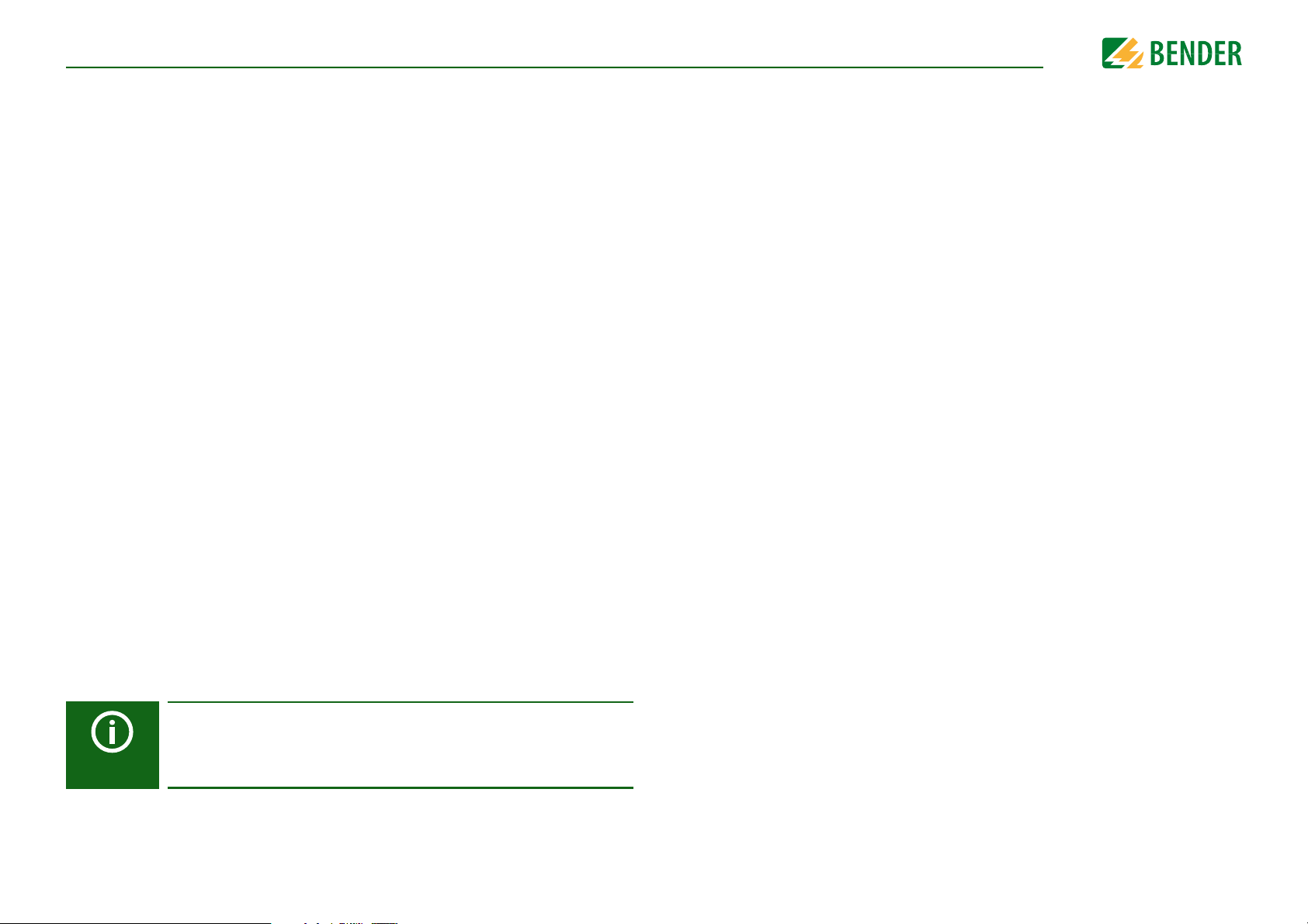
After switching on the supply voltage, the ISOMETER automatically and continuously
checks all internal measuring functions, the components of the process control such as
the data and parameter memory, as well as the connections to the IT system and earth.
Additionally, all EDS devices connected to the ISOMETER® are tested.
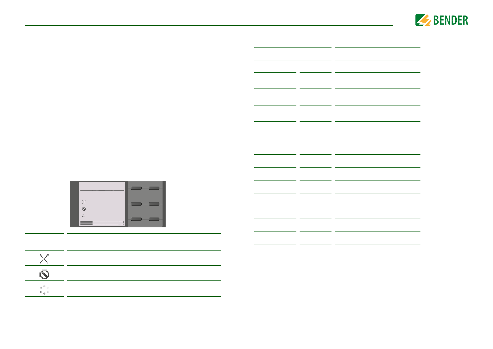
The self test can also be activated manually by means of the test button to check the functions of the relays (depending on the configuration) or it can be selected via the "Control"
menu (refer to page 59).
The progress of the manual self test is shown on the LC display by a bar graph. Depending
on the conditions in the IT system being monitored, the self test is completed after
15…20 seconds. The device then returns to the standard mode (measurement mode)
and the actual measured value will be displayed after the measuring time has expired.
The display shows the message
Initial measurement
ured (refer to “Initial measurement” on page 40).
If a fault is detected during the self test, the respective LEDs of the device light (refer to
“Alarm messages” on page 78). In addition, the respective message will be indicated on
the display and a previously programmed output will provide the respective signal.
TEST
√ Messtechnik
Ankopplung
Anschluss Erde
Ausgänge
33 %
until the first valid value is meas-
3.7 Compatibility with EDS
Device Notes
iso685-x-P
EDS440-L
EDS440-S
EDS441-L
EDS441-S
EDS441-LAB
EDS460/490L
EDS460/490D
EDS461/491L
EDS461/491D
EDS150
EDS151
I
O
I
O
I
I
I
I
I
–
–
EDS440-L
EDS440W-L
EDS440-S
EDS440W-S
EDS441-L
EDS441W-L
EDS441-S
EDS441W-S
EDS441-LAB
EDS441W-LAB
Not recommended for new systems
Not recommended for new systems
Not recommended for new systems
Not recommended for new systems
EDS150 B9108 0103
EDS151 B9108 0101
B91080202
B91080202W
B91080201
B91080201W
B91080205
B91080205W
B91080204
B91080204W
B91080207
B91080207W
14
The test has been run and the result was positive.
The test has been run and the result was negative.
The test is not available and is not carried out
(e.g. due to specific device settings).
The test is running.
EDS195P X EDS195P B91082040
Legend:
X = can be combined
I = can be combined + communication via BS bus
O = can be combined + communication via BB bus
– = limited compatibility + communication via BS bus
No indication of messages on the ISOMETER®.
Parameter setting via the ISOMETER® not possible.
Local fault indication on EDS only.
iso685-D-P_D00170_00_M_XXDE/06.2016
Page 15
4. Device overview
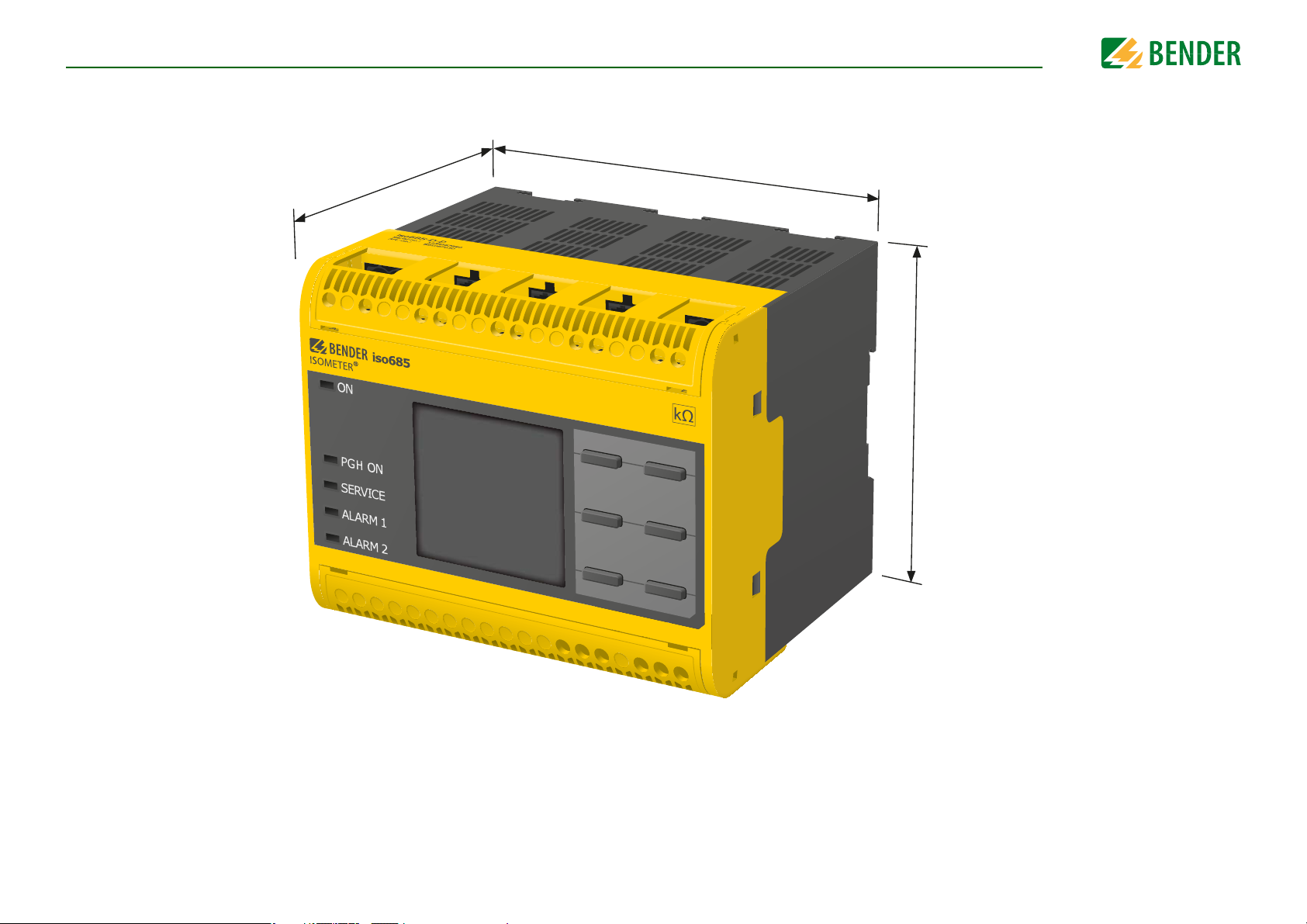
4.1 Dimensions
108 mm
110 mm
mm 39
15
iso685-D-P_D00170_00_M_XXDE/06.2016
Page 16

Device overview
ISOMETER® iso685(W)-D-P
ISOMETER® iso685(W)-S-P connected to front panel FP200 via an RJ45 cable
4.2 Device variants
iso685-D-P:
iso685-S-P:
Option "W":
The device variant ISOMETER® iso685-D-P features a high-resolution graphic LC display and operating controls for direct operation of the device functions.
It cannot be combined with an FP200.
The device variant ISOMETER® iso685-S-P features neither a display nor operating controls.
It can only be used in combination with the FP200 and it is operated via this front panel.
The ISOMETER®s with and without integrated display are available with option "W" for extreme climatic and mechanical conditions
(ISOMETER® iso685W-D-P and iso685W-S-P).
16
iso685-D-P_D00170_00_M_XXDE/06.2016
Page 17
Device overview
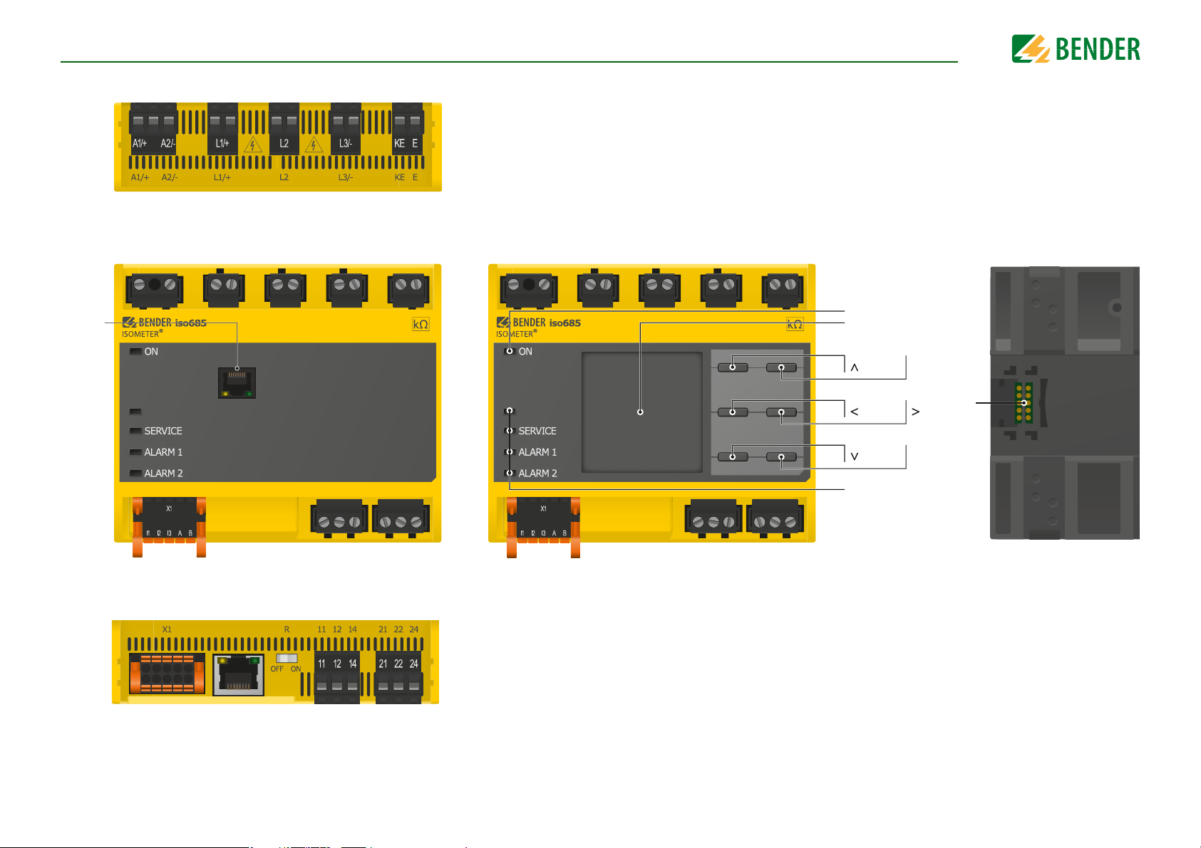
A1/+, A2/- Connection to the power supply voltage U
s
L1/+ Connector for the IT system to be monitored
L2 Connector for the IT system to be monitored
L3/- Connector for the IT system to be monitored
KE, E Connection to PE
To p
PGH ON
ON
RESET
DATA
LEDs: PGH ON, SERVICE,
ALARM 1, ALARM 2
MENU
ESC
TEST
INFO
OK
X3
EDS
iso685-D-P
PGH ON
X4
X3 Optional expansion module for Bender devices (e. g. BB-Bus)
X4 REMOTE interface to connect to the FP200
iso685-S-P
Back
Front
ETH
X1 Multifunctional I/O interface (refer to page 23)
ETH Ethernet interface
R Switchable terminating resistor for termination
of the RS-485 interface
11 12 14 Connector for alarm relay 1
21 22 24 Connector for alarm relay 2
Bottom
4.3 Connections and panel
17
iso685-D-P_D00170_00_M_XXDE/06.2016
Page 18
Device overviewDevice overview
PGH ON
1
7
8
9
10
11
12
2
3
4
5
6
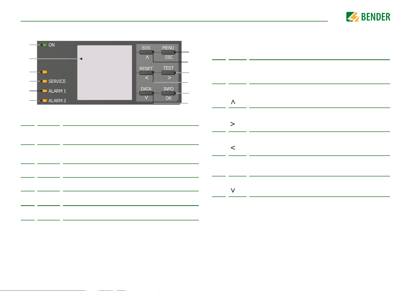
4.4 Display elements and device buttons
Display elements
The LED "ON" lights when the device is turned on.
1ON
2
3PGH ON
4
5
6
SERVICE
ALARM 1
ALARM 2
The LED "ON" flashes during ISOnet operation if the device is active in
the ISOnet interconnection.
The device display shows information regarding the device and the
measurements.
Other information is available in the chapter “Display” from page 36.
The LED "PGH ON" flashes
the locating current for the insulation fault location is generated.
The LED "SERVICE" lights when there is either a device fault or a connection fault, or when the device is in maintenance mode.
The LED "ALARM 1" lights when the insulation resistance of the IT system
falls below the set response value R
The LED "ALARM 2" lights when the insulation resistance of the IT system
falls below the set response value R
during insulation fault location
an1
an2
Device buttons
You can adjust the device settings in the respective menu using the menu buttons.
Depending on the menu entry, one of the options displayed below is assigned to the
buttons.
MENU Opens the device menu.
7
ESC
EDS
8
TEST
9
RESET
10
Info
. It indicates that
11
OK
DATA
12
.
.
Cancels the current process or
navigates one step back in the device menu.
Manually starts the insulation fault location, which runs continuously.
Stops the insulation fault location immediately when it is pressed again.
Navigates up in a list or increases a value.
Starts the device self test.
Navigates forwards (e.g. to the next setting step) or
selects a parameter.
Resets alarms.
Navigates backwards (e.g. to the previous setting step) or
selects a parameter.
Shows information.
Confirms an action or a selection.
Indicates data and values.
Navigates down in a list or reduces a value.
18
iso685-D-P_D00170_00_M_XXDE/06.2016
Page 19
5. Mounting
DANGER
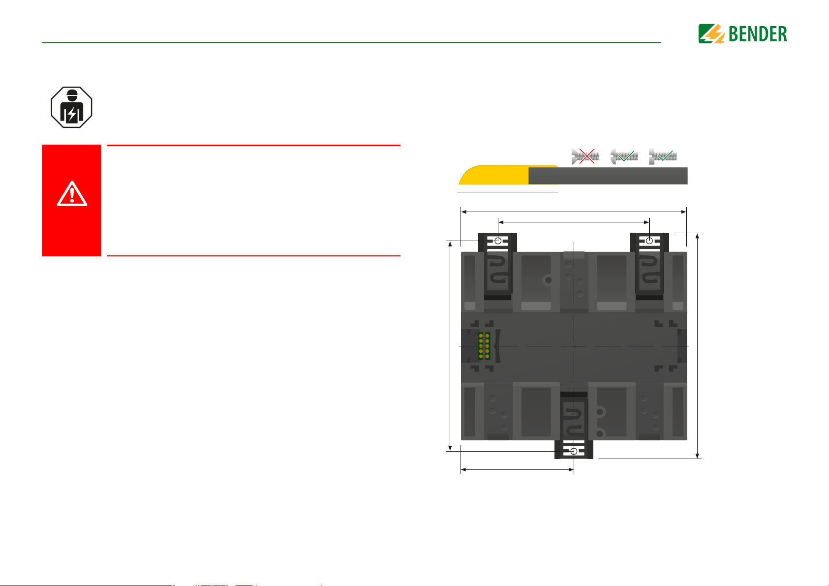
72 mm
108 mm
54 mm
100 mm
107,3 mm
Mounting
5.1 General instructions
Only qualified personnel are permitted to carry out the work necessary
to install, commission and run a device or system.
Risk of electrocution due to electric shock!
Touching live parts of the system carries the risk of:
• An electric shock
• Damage to the electrical installation
• Destruction of the device
Before installing and connecting the device, make sure that the installation has been de-energised. Observe the rules for working on elec-
trical installations.
5.2 Screw mounting
19. Fix the three mounting clips delivered with the device (two of them packed separately) manually or using a tool, as illustrated below.
20. Drill the mounting holes for the M4 thread according to the dimensioned drilling
template.
21. Fix the ISOMETER® using three M4 screws.
19
iso685-D-P_D00170_00_M_XXDE/06.2016
Page 20
Connection
DANGER
DANGER
DANGER
WARNING
6. Connection
5.3 DIN rail mounting
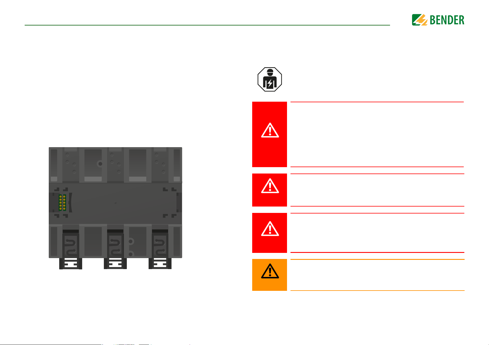
1. Fix the three mounting clips delivered with the device (two of them packed separately) manually or using a tool, as illustrated below.
2. Snap the ISOMETER® securely onto the DIN rail.
6.1 Connection requirements
Consider the minimum distance to adjacent devices:
lateral 0 mm, top 20 mm, bottom 20 mm.
Only qualified personnel are permitted to carry out the work necessary
to install, commission and run a device or system.
Risk of electrocution due to electric shock!
Touching live parts of the system carries the risk of:
• An electric shock
• Damage to the electrical installation
• Destruction of the device
Before installing and connecting the device, make sure that the installation has been de-energised. Observe the rules for working on elec-
trical installations.
Risk of electric shock!
Nominal voltages up to 1000 V may be present on the terminals L1/+ to
L3/- which can be lethal. Make sure the terminal covers are properly
mounted and clicked in before putting the device into operation.
20
Risk of electric shock!
High voltage is applied at the terminals, which in case of direct contact
can be life-threatening. If the terminals L1/+, L2, L3/- of the device are connected to a live IT system, the terminals E and KE must not be disconnected
from the protective conductor (PE).
Warning of insulation monitoring devices that do not work correctly!
Connect the terminals KE and E individually to the protective earth conductor PE.
iso685-D-P_D00170_00_M_XXDE/06.2016
Page 21
ConnectionConnection
CAUTION
CAUTION
CAUTION
CAUTION
CAUTION
Provide line protection!
According to DIN VDE 0100-430, a line protection shall be provided for the
supply voltage.
Risk of injury from sharp-edged terminals!
Risk of lacerations.
Touch the enclosure and the terminals with due care.
Ensure disconnection from the IT system!
When insulation or voltage tests are to be carried out, the device must be
isolated from the system for the test period. Otherwise the device may be
damaged.
Risk of property damage due to unprofessional installation!
If more than one insulation monitoring device is connected to a conductively connected system, the system can be damaged. If several devices
are connected, the device does not function and does not signal insulation faults. Make sure that only one insulation monitoring device is connected in each conductively connected system.
The ISOMETER® is suited for use in coupled systems. For the required parameter setting, refer to “Special functions for coupled IT systems” from
page 70.
Prevent measurement errors!
When an AC system being monitored contains galvanically coupled DC
circuits, take into consideration that: an insulation fault can only be detected correctly when the rectifier valves carry a minimum current of
>10 mA.
For UL applications:
Use 60/70 °C copper lines only!
For UL and CSA applications, the supply voltage must be protected via 5 A
fuses.
21
Risk of property damage due to unprofessional installation!
The connecting lines L1/+, L2, L3/- to the system to be monitored must be
carried out as spur lines. Inadmissible load current can result in damage
to property and personal injury. Do not apply any load current to the terminals.
Check proper connection!
Prior to commissioning of the installation, check that the device has been
properly connected and check the device functions. Perform a functional
test using an earth fault via a suitable resistance.
iso685-D-P_D00170_00_M_XXDE/06.2016
Page 22

ConnectionConnection
WARNING
L1
L2
L3
N
PE
U
S
U
n
WARNING
L1
L2
PE
U
n
U
S
6.2 Connection to a 3(N)AC system
Risk of injury, fire and damage to property due to a short circuit!
According to DIN VDE 0100-430, devices used to protect against a short
circuit when terminals L1/+, L2 und L3/- are coupled to the IT system to be
monitored can be omitted if the wiring is carried out in such a manner as
to reduce the risk of a short circuit to a minimum. Ensure short-circuitproof and earth-fault-proof wiring.
6.3 Connection to an AC system
Risk of injury, fire and damage to property due to a short circuit!
According to DIN VDE 0100-430, devices used to protect against a short
circuit when terminals L1/+, L2 und L3/- are coupled to the IT system to be
monitored can be omitted if the wiring is carried out in such a manner as
to reduce the risk of a short circuit to a minimum. Ensure short-circuitproof and earth-fault-proof wiring.
22
Position the terminal cover and click it into place
Position the terminal cover and click it into place
iso685-D-P_D00170_00_M_XXDE/06.2016
Page 23
ConnectionConnection
WARNING
L+
L-
PE
U
S
U
n
I1
I2
I3
A
B
M+
Q2
Q1
+
Electrical overload protection.
Auto shut-off in the event of a short
circuit and transients (resettable)
Input 1
Input 2
Input 3
RS-485 A
RS-485 B
Ground
Analogue output
Output 2
Output 1
+24 V
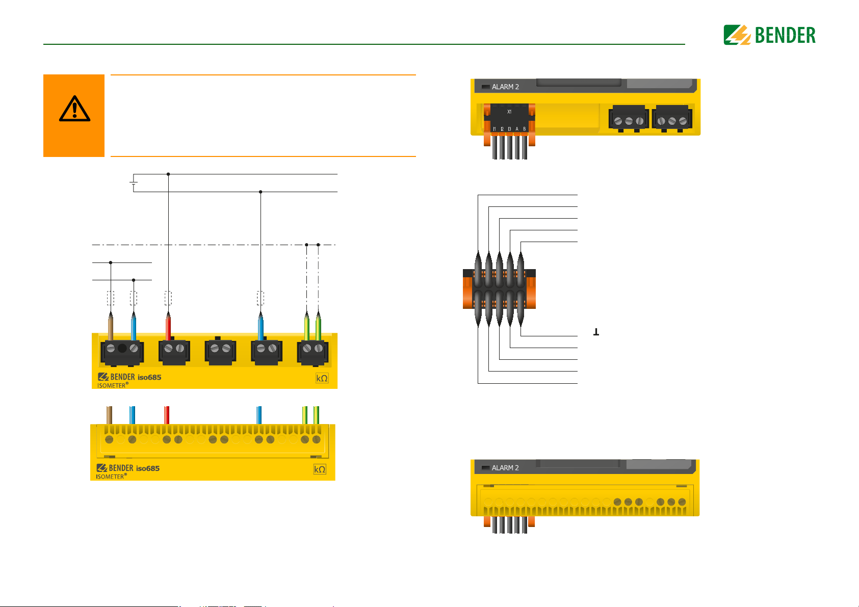
6.4 Connection to a DC system
Risk of injury, fire and damage to property due to a short circuit!
According to DIN VDE 0100-430, devices used to protect against a short
circuit when terminals L1/+, L2 und L3/- are coupled to the IT system to be
monitored can be omitted if the wiring is carried out in such a manner as
to reduce the risk of a short circuit to a minimum. Ensure short-circuitproof and earth-fault-proof wiring.
6.5 Connection to the X1 interface
23
Position the terminal cover and click it into place
For systems > 690 V and with overvoltage category III a fuse for
the connection to the system to be monitored must be provided.
Recommendation: 2 A fuses.
Position the terminal cover and click it into place
iso685-D-P_D00170_00_M_XXDE/06.2016
Page 24
ConnectionConnection
CAUTION
U
S
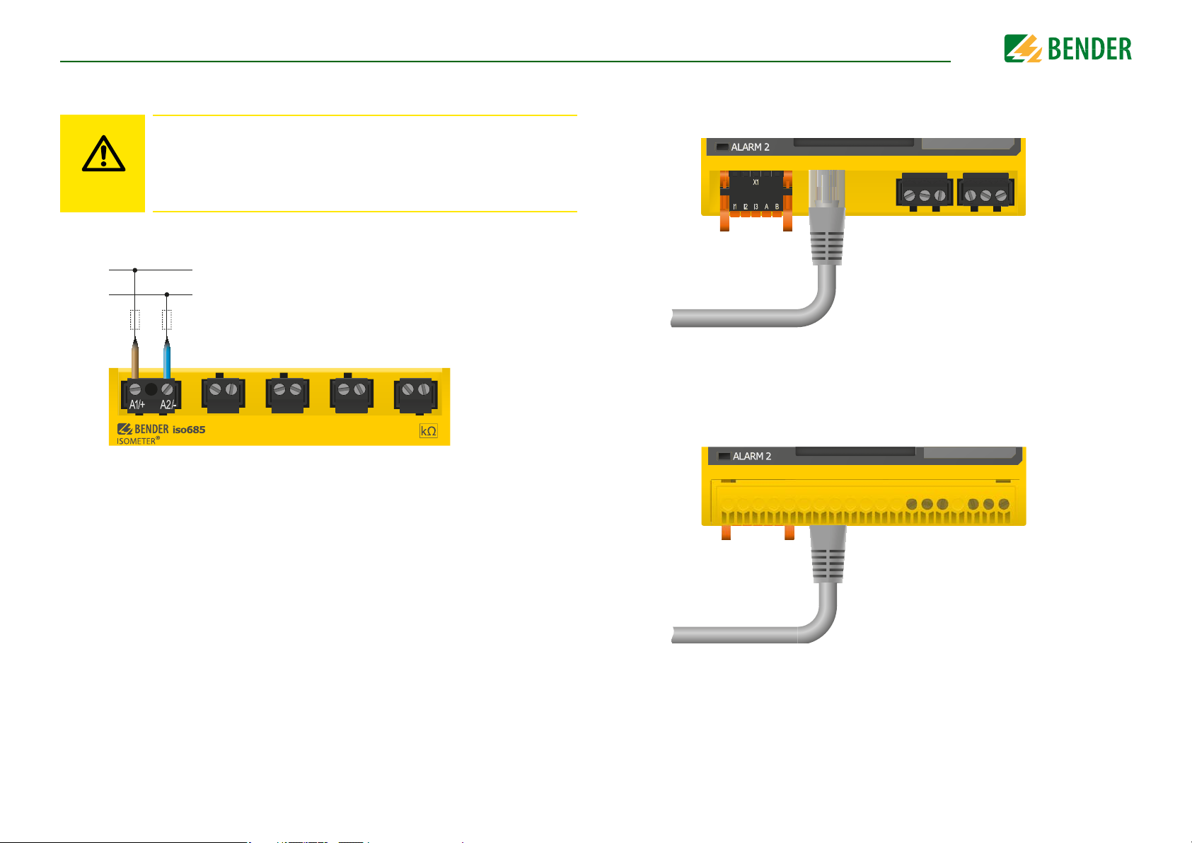
6.6 Connection to the supply voltage
Danger of damage to property due to faulty connections!
The device can be damaged if the unit is simultaneously connected to the
supply voltage via the X1 interface, and A1/+ and A2/- terminals. Do not
connect the device simultaneously via X1, and A1/+ and A2/- to different
supply voltages.
6.7 Connection to the Ethernet interface
Position the terminal cover and click it into place
24
iso685-D-P_D00170_00_M_XXDE/06.2016
Page 25
ConnectionConnection
11
12
14
Relais 1
Gemeinsamer Kontakt
Schließer
21
22
24
Relais 2
Gemeinsamer Kontakt
Schließer
Öffne
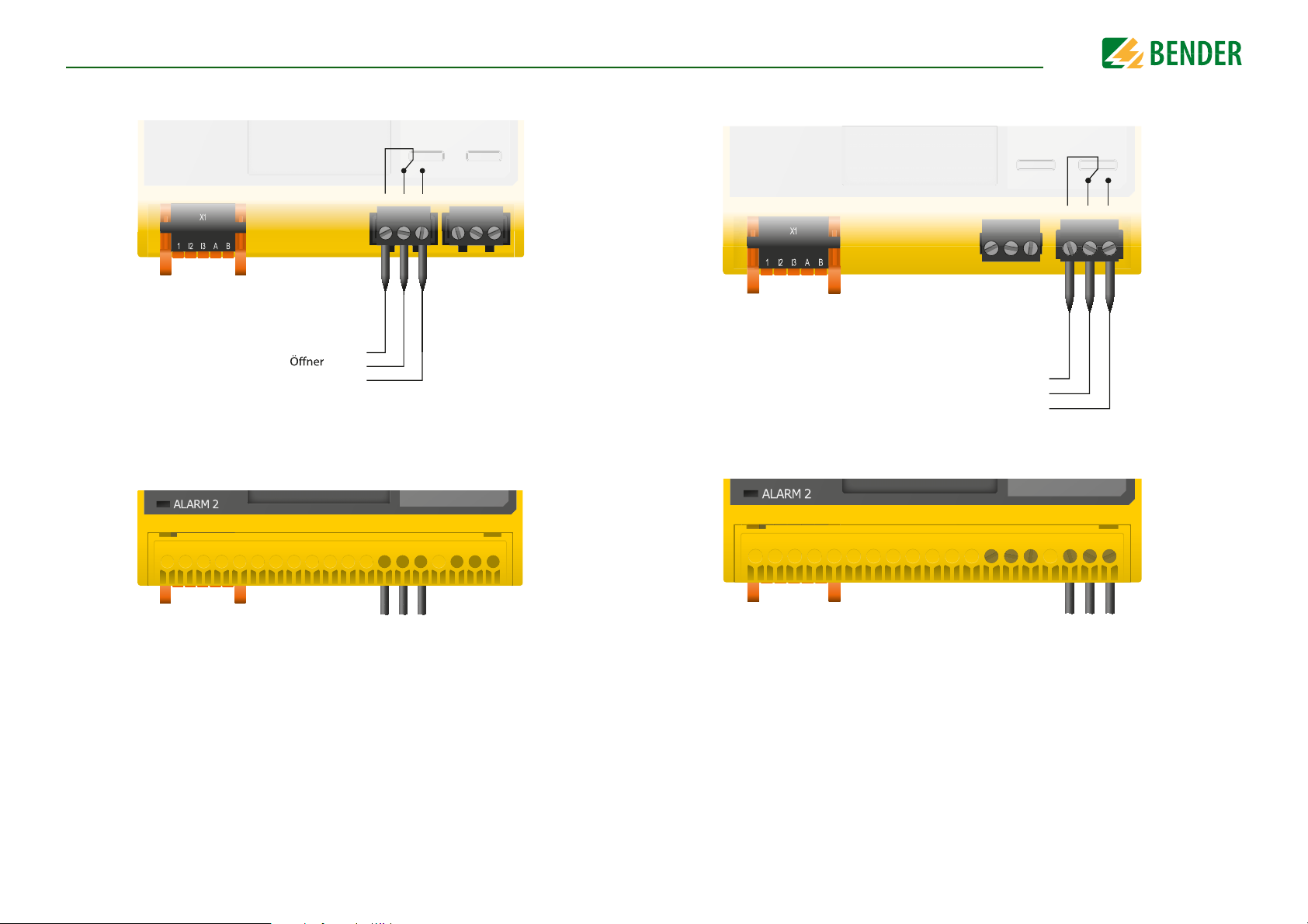
6.8 Connection to the relay 1 interface (11 12 14)
Position the terminal cover and click it into place
6.9 Connection to the relay 2 interface (21 22 24)
Position the terminal cover and click it into place
25
iso685-D-P_D00170_00_M_XXDE/06.2016
Page 26
ConnectionConnection
CAUTION
CAUTION
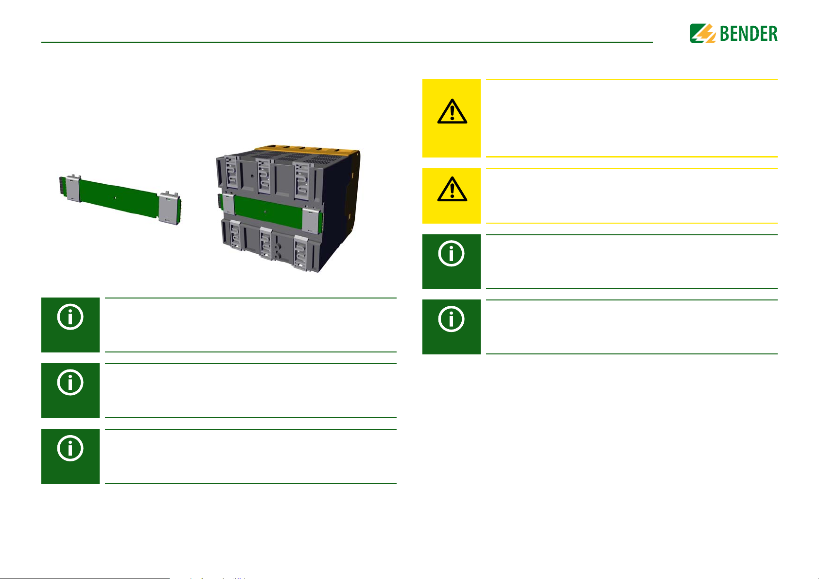
6.10 Connection to the BB bus
The BB bus is an interface that enables Bender devices to communicate with each other.
The BB bus can be used with an ISOMETER® and one or more EDS44…-S. For this purpose,
the BB bus is installed at the rear side of both devices and afterwards, both devices are
mounted next to each other on the DIN rail. For further information, refer to the quickstart guide enclosed to the BB bus PCBs.
Sensor variant devices that are additionally connected to the ISOMETER®
do not require additional supply voltage when the devices are connected
to the BB bus via X3.
6.11 Connecting the EDS to the ISOMETER®
Risk of malfunctions due to excessive locating current on sensitive
system parts!
The locating current flowing between the IT system and earth can cause
controller faults in sensitive parts of the system, such as the PLC or relay.
Ensure that the level of the locating current is compatible with the system
to be monitored.
Risk of incorrect measurement
The supplied locating current may influence other connected insulation
fault location systems. If they measure the injected locating current, the
measurement might be incorrect.
Insulation monitoring is deactivated
while the insulation fault location is active.
The EDS44…-S must be connected to the ISOMETER® via the BB bus.
The EDS44…-L must be connected to the ISOMETER® via the BS bus.
26
A maximum of two EDS44…-S can be connected to an ISOMETER®.
When the BB bus is installed, the EDS44… must always be mounted on the
right side of the ISOMETER®. In addition, for protection against short circuits, a BB bus end bracket must be mounted to each first and last device
on the DIN rail featuring a BB bus.
iso685-D-P_D00170_00_M_XXDE/06.2016
Page 27
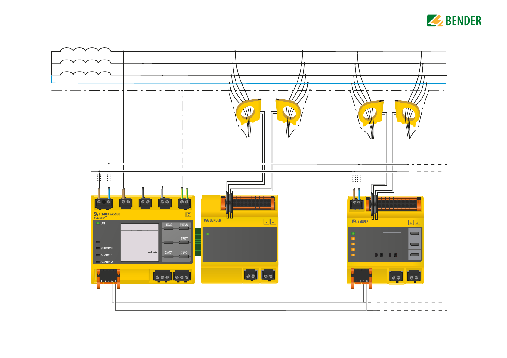
Connection
6.11.1 Connection example ISOMETER® to EDS
U
n
L1
L2
L3
N
PE
U
S
A1/+ A2/-
PGH ON
X1
L1/+
IT-System
>20
23 s
R(an)
4 0 kΩ/10kΩ
to the loads to the loads
I LI
n
L2
L3/-
O
K
O K
MΩ
MΩ>20
KE E
ISOSCAN®
BB-Bus
EDS440
ON
ON
to the loads to the loads
A1/+ A2/-
EDS440
ISOSCAN®
ON
COM
SERVICE
ALARM
ALARM
EDS440
CHANNELS
1 2 3456
87
5
6
SLAVE ADDRESS
I
∆
L
7
0
I
1
∆
n
ISOSCAN®
X1
ll
iso685-D-P EDS44…-S EDS44…-L
BS-Bus
I LI
n
I
L
TEST
11109
4
5
3
6
2
7
1
8
0
9
RESET
12
3
4
2
1
MUTE
0
27
iso685-D-P_D00170_00_M_XXDE/06.2016
Page 28

Connection
BS-Bus
PGH ON
IT-System
O
K
R(an)
4 0 k Ω/10kΩ
O
K
>20
MΩ>20
MΩ
L1
L2
L3
N
PE
U
S
U
n
to the loads to the loads
A1/+ A2/-
L1/+
L3/-
L2
KE E
X1
ISOSCAN®
EDS440
I
L
7
6
5
3
8
4
2
0
1
6
5
3
4
2
0
1
9
8
EDS440
ISOSCAN®
TEST
MUTE
RESET
ALARM
ALARM
ON
COM
SERVICE
CHANNELS
SLAVE ADDRESS
12
11109
87
123456
1
7
I LI
n
I
∆
L
I
∆
n
A1/+ A2/-
l
k
1 2 3 4 5 6 7 8 9 10 11 12
13 14 23 24X1
U
S
A1 A2
ll
X1
6.11.2 Connection to a 3(N)AC system
28
iso685-D-P_D00170_00_M_XXDE/06.2016
Page 29

Connection
BS-Bus
IT-System
O
K
R(an)
4 0 k Ω/10kΩ
O
K
>20
MΩ>20
MΩ
L1
L2
PE
U
S
U
n
to the loads
to the loads
PGH ON
A1/+ A2/-
L1/+
L3/-
L2
KE E
X1
ISOSCAN®
EDS440
I
L
7
6
5
3
8
4
2
0
1
6
5
3
4
2
0
1
9
8
EDS440
ISOSCAN®
TEST
MUTE
RESET
ALARM
ALARM
ON
COM
SERVICE
CHANNELS
SLAVE ADDRESS
12
11109
87
123456
1
7
I LI
n
I
∆
L
I
∆
n
ll
X1
13 14 23 24X1
A1/+ A2/-
l
k
1 2 3 4 5 6 7 8 9 10 11 12
U
S
A1 A2
6.11.3 Connection to an AC system
29
iso685-D-P_D00170_00_M_XXDE/06.2016
Page 30
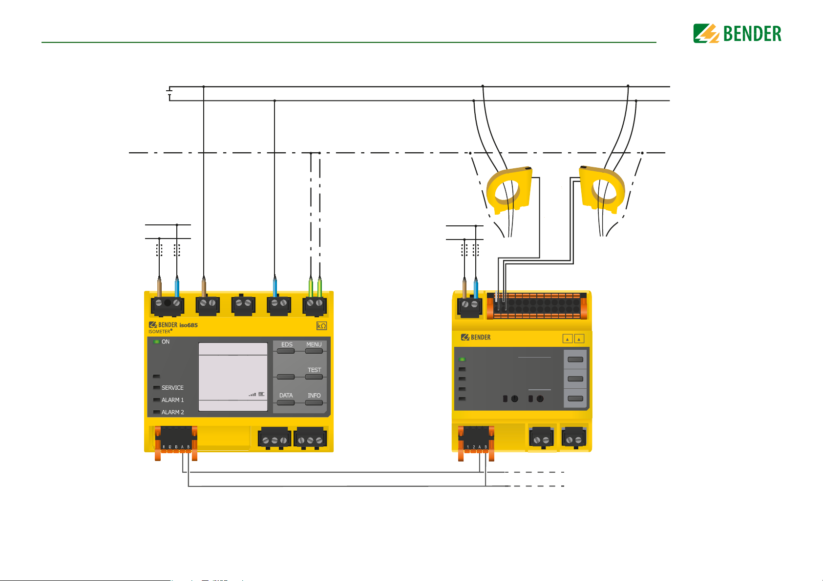
Connection
BS-Bus
IT-System
O
K
R(an)
4 0 k Ω/10kΩ
O
K
>20
MΩ>20
MΩ
L+
L-
PE
U
S
U
n
to the loads
to the loads
A1/+ A2/-
L1/+
L3/-
L2
KE E
X1
ISOSCAN®
EDS440
I
L
7
6
5
3
8
4
2
0
1
6
5
3
4
2
0
1
9
8
EDS440
ISOSCAN®
TEST
MUTE
RESET
ALARM
ALARM
ON
COM
SERVICE
CHANNELS
SLAVE ADDRESS
12
11109
87
123456
1
7
I LI
n
I
∆
L
I
∆
n
ll
X1
A1/+ A2/-
l
k
1 2 3 4 5 6 7 8 9 10 11 12
13 14 23 24X1
U
S
A1 A2
PGH ON
6.11.4 Connection to a DC system
For systems > 690 V and with overvoltage category III a fuse for the connection to the system to be monitored must be provided.
Recommendation: 2A screw fuses.
30
iso685-D-P_D00170_00_M_XXDE/06.2016
Page 31

Connection
PGH ON
IT-System
O
K
R(an)
4 0 kΩ/10kΩ
O
K
>20
MΩ>20
MΩ
A1/+ A2/-
L1/+
L3/-L2KE E
X1
ISOSCAN®
EDS440
EDS441
ISOSCAN®
I LI
n
ON
PLC Input Output
VFD
AC 24 V
DC 110 V
L1
L2
PE
U
S
U
n
M
6.11.5 System structure
The application example below shows the monitoring of a control system with the ISOMETER® iso685-D-P and the EDS441-S.
31
iso685-D-P_D00170_00_M_XXDE/06.2016
Page 32

7. Commissioning
Commissioning the ISOMETER
®
Adjust basic settings if
necessary
Control and/or connect the EDS
to the ISOMETER
®
:
* EDS44…-L: use BS bus
* EDS44…-S: use BB-Bus
Make any other necessary
settings for the EDS44… in the
ISOMETER
®
menu: EDS
Set the maximum locating current
in the ISOMETER
®
menu:
EDS General Current
* EDS440…: 10…50 mA
* EDS441…: 1…5 mA
Install the device according to the
wiring diagram
and documentation
Connect the supply voltage
Connect the system voltage
The ISOMETER
®
performs a self
test
Function test with a suitable
resistance between system and
earth. Resistance value: 50% of
the response value Alarm 2
Remove the resistance
The ISOMETER
®
is properly
connected and
functions reliably
Commissioning the EDS44…
Function test with a suitable
resistance between system and
earth. Resistance value: 50% of
the response value Alarm 2
Remove the resistance
The ISOMETER
®
and EDS44...
combination is properly connected
and functions reliably
Set BS address = 1 (Master)
System commissioning of
ISOMETER
®
with EDS44…
Install the device according to the
wiring diagram and documentation
Connect the supply voltage
Delete the alarm messages as
described in the device
documentation
The EDS44… is properly
connected and ready for operation
Disconnect supply voltage
of all devices
Connect the supply voltage
to all devices
Search for adjustable measuring
channels in the ISOMETER
®
menu: EDS Scan for channels
Activate measuring channels in
ISOMETER
®
menu:
EDS Enable channel
Run the commissioning
wizard
The ON LED flashes until the
device is ready for use
Set EDS mode in the ISOMETER®
menu: EDS General
Mode
EDS44…-L:
Set the BS adress using
the rotary switches on the EDS
For further information regarding device settings, refer to chapter “Settings”
from page 44.
Commissioning
7.1 General initial commissioning process
1. Check that the ISOMETER® is properly connected to the system to be monitored.
2. Connect the supply voltage to the ISOMETER®. Adjust the device using the commissioning wizard. Afterwards, the ISOMETER® performs a self test in four steps. The
alarm relays are not checked during this test. After completion of the test, the measured insulation resistance is shown on the display. If the value exceeds the response
values indicated in the lowest line of the display, the message "OK" will additionally
be displayed.
3. Check the ISOMETER® in the system being monitored, e.g. using a suitable resistance
to earth.
After setting the response value R
first measurement and outputs the measured insulation resistance values of the IT system being monitored, then commissioning is completed.
For customer-specific configured devices, the commissioning wizard
might be deactivated and cannot be run. In this case, the device is preset.
However, the commissioning wizard can be started as described at
“Recommissioning” on page 34.
Observe device status!
The device is in an alarm state until initial commissioning has been
completed.
for alarm 2, the device starts a self test, makes the
an2
Commissioning flow chart
32
iso685-D-P_D00170_00_M_XXDE/06.2016
Page 33
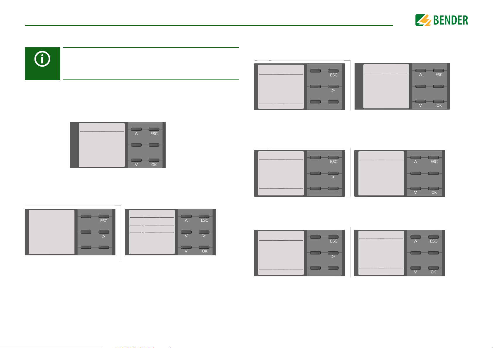
CommissioningCommissioning
Date 5.2.4
14.01.2014
min. 1
max. 31
Commissioning 6.6
2/9
Please set the
current date
and time.
6.6.6
• DC
o AC
o 3AC
System type
6.6
5/11
Commissioning
Please choose the
type of system
that best suits
your installation.
6.6.7
Profile
• Power circuits
o Control circuits
o Generator
o High capacitance
o Inverter>10 Hz
o Inverter<10 Hz
Commissioning 5.6
Please select a
profile that suits
your application.
7/9
Mode
•
manual
o
auto
o
1 cycle
6.6.8
Commissioning 6.6
Please select the
EDS mode.
7/11
7.2 Initial commissioning
Check network function!
When the device has been integrated into a network, the influence on the
network has to be checked with the device switched on and off.
Follow the instructions of the commissioning wizard on the display.
7.2.1 Set language
The language selected here will be used in the menu and for device messages.
Language
• Deutsch
o English
o ...
7.2.2 Set time and date
Alarm messages in the history memory and the insulation resistance value over time can
only be assigned correctly to the isoGraph when the date and time are set correctly.
6.6.2
7.2.3 Setting system type
By setting the system type the insulation monitoring device can be optimally adapted to
the system to be monitored. The system type is essential information for the insulation
monitoring device in order to determine the insulation resistance correctly.
7.2.4 Set profile
In order to optimally adapt the insulation monitoring device to the system to be monitored, select a profile here that suits your system. For an overview of the profiles refer to
“Device profiles” on page 73. The profile "Power circuits" is suitable for most IT systems.
7.2.5 Setting EDS mode
Set the mode for the insulation fault location to manual, automatic or 1 cycle.
For further information, refer to “Mode” on page 52.
33
iso685-D-P_D00170_00_M_XXDE/06.2016
Page 34
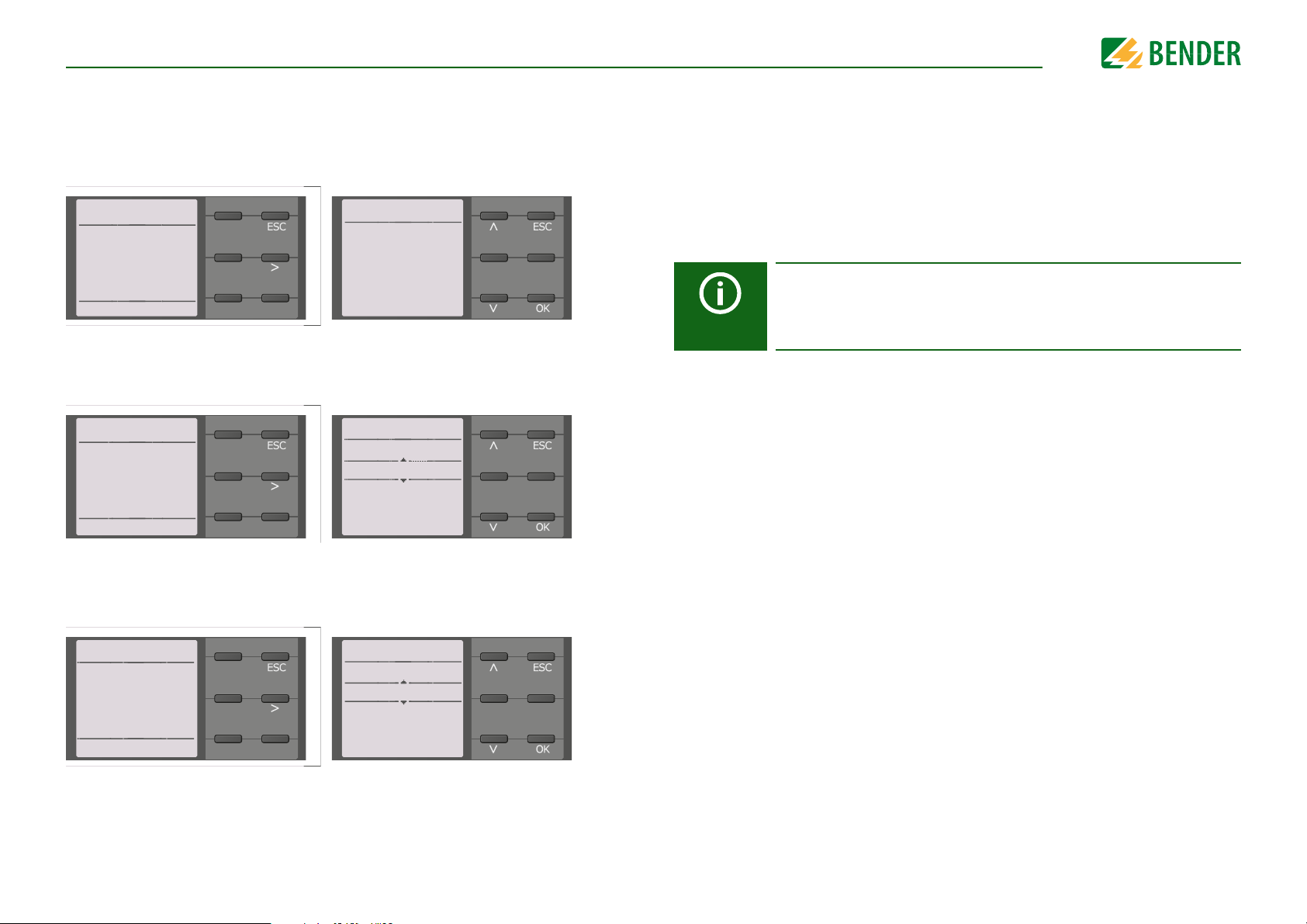
CommissioningCommissioning
Current
6.6.9
o 1mA
o 1.8mA
o 2.5mA
o 5mA
• 10mA
Commissioning 6.6
Please select
the locating
current
8/11
Alarm 1 5.6.8
40 kΩ
Min. 1 kΩ
Max.
10MΩ
Commissioning 5.6
Please set a
response value
for R(an1) for
Alarm 1.
7/9
Alarm 2 5.6.9
10 kΩ
Min.
Max.
1 kΩ
10MΩ
Commissioning 5.6
Please set a
response value
for R(an2) for
Alarm 2.
8/9
7.2.6 Setting EDS current
Set the maximum locating current.
EDS441: 1-5 mA
EDS440: 10-50 mA
For further information, refer to “Current” on page 51.
7.2.7 Set response value R
You can set the prewarning response value here.
A value of 100 Ω/V is recommended for prewarning.
for alarm 1
an1
7.3 Recommissioning
If the device has already been put into operation once, the self test will be carried out
shortly after connecting the supply voltage. The commissioning wizard will not restart.
You can restart the commissioning wizard using the following menu path:
Menu/Device settings/Commissioning
This menu can be used to modify settings made previously.
Observe device status!
Once initial commissioning has been completed and the initial measurement has been taken, the device changes from the alarm state to normal
state by adhering to the set response values.
7.2.8 Set response value R
You can set the response value for the main alarm here.
A value of 50 Ω/V is recommended for the main alarm.
34
for alarm 2
an2
iso685-D-P_D00170_00_M_XXDE/06.2016
Page 35
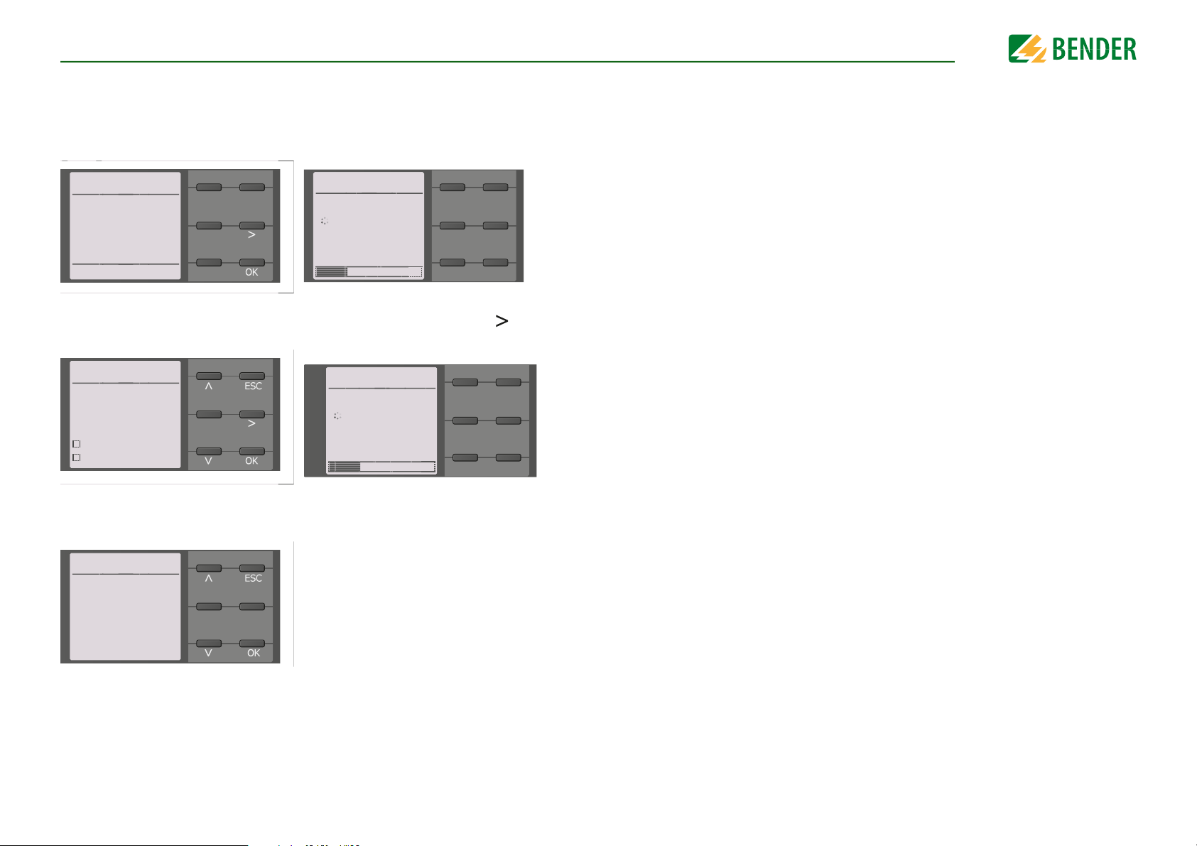
7.4 Commissioning EDS
Channel
√ BB-Bus
BS-Bus
33 %
Scanning channels 2.2
Search for
EDS channels?
Cancel Start
Channel
√ BB-Bus
BS-Bus
33 %
Activating channels 2.3
Select all
No selection
Invert selection
Channel 1
Channel 2
Current
6.6.9
o 1mA
o 1.8mA
o 2.5mA
o 5mA
• 10mA
Proceed as follows to put into operation an EDS after commissioning the ISOMETER®:
1. First, search for all available measuring channels.
Menu path: Menu/EDS/Scan channels.
2. Activate all or only selected measuring channels. Additionally, select the required
menu item, confirm your selection with "OK" and start activation with
Menu path: Menu/EDS/Activate channel.
CommissioningCommissioning
3. Test if the maximum locating current to the EDS is correct and adjust if necessary
(refer to 7.2.6 “Setting EDS current” on page 34).
Menu path: Menu/EDS/General/Current
In addition to this chapter, commissioning of the ISOMETER® in combination with an EDS
is described in the “Commissioning flow chart” on page 32.
35
iso685-D-P_D00170_00_M_XXDE/06.2016
Page 36
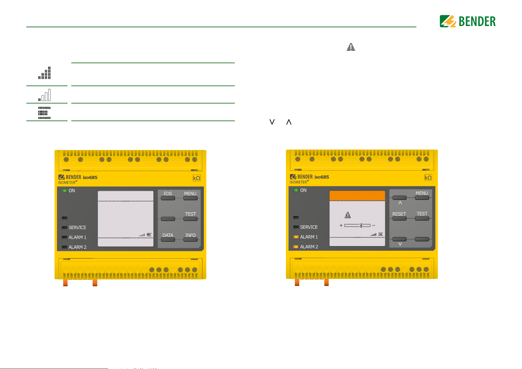
8. Display
IT System
OK
230 kΩ
R(an) 40kΩ/10kΩ
OK
230 kΩ
PGH ON
Display
8.1 Standard display
During normal operation, the ISOMETER® displays the message OK and below, the currently measured insulation resistance.
The signal quality of the measurement suits the selected profile.
The better the signal quality, the faster and more exact the device can
measure.
The signal quality of the measurement does not suit the selected profile. Select a different measurement profile.
Update period between the test pulses
In the bottom line of the display, the set limit values for R(an) are indicated. In the example below, R
=40 kΩ and R
an1
an2
=10 kΩ.
8.2 Fault display (active)
An active fault is displayed by . The upper part of the display will become orange and
displays the fault message.
Depending on the type of fault, the LEDs ALARM 1, ALARM 2 or SERVICE are activated.
In the example below, the insulation resistance is still 7 kΩ. Since the values R
and R
triggered.
If several fault messages have appeared, you can navigate through the faults using the
=10 kΩ are both below the set response value, ALARM 1 and ALARM 2 have been
an2
and button.
Insulation fault
PGH ON
7 kΩ
7 kΩ
=40 kΩ
an1
36
1/4
If the value falls below R
ditional detailed information regarding the DC offset will be displayed as illustrated
above.
in a DC system or a DC offset is detected in an AC system, ad-
an1
iso685-D-P_D00170_00_M_XXDE/06.2016
Page 37
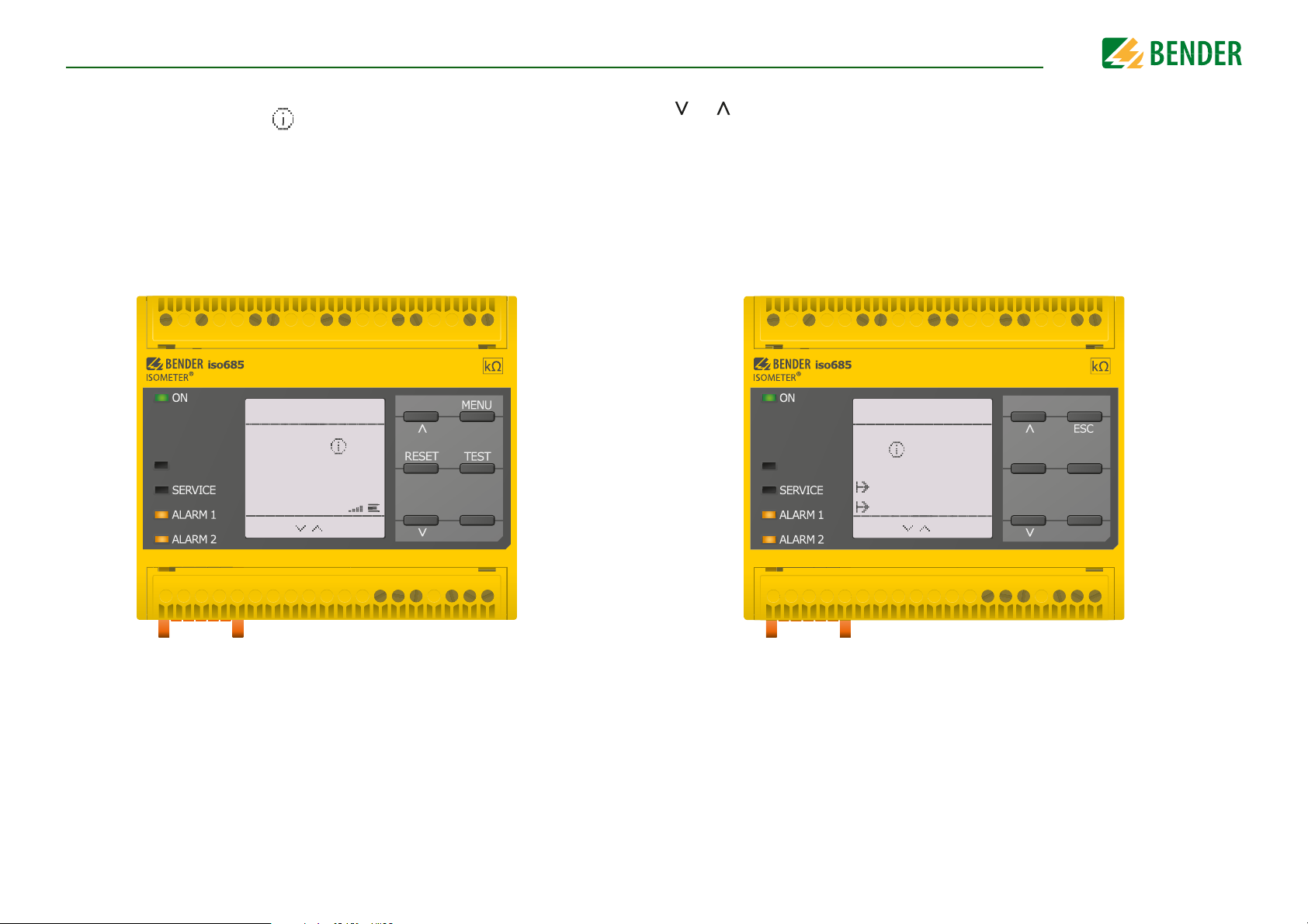
DisplayDisplay
230 kΩ
IT System
3x
1/4
230 kΩ
PGH ON
7 kΩ
Insulation fault
28.0 3.14 17:02
28.0 3.14 17:18
2/4
7 kΩ
PGH ON
8.3 Fault display (inactive)
An inactive fault is displayed by . If several faults have occurred, the number of faults
will also be indicated.
The message shown on the display below means that there has been a fault in the past
but the device is no longer in fault condition.
If several fault messages have appeared, you can navigate through the faults using the
and buttons. In addition to the type of fault and the associated alarm value, you can
see when the fault has occurred and for how long it has been active.
37
iso685-D-P_D00170_00_M_XXDE/06.2016
Page 38
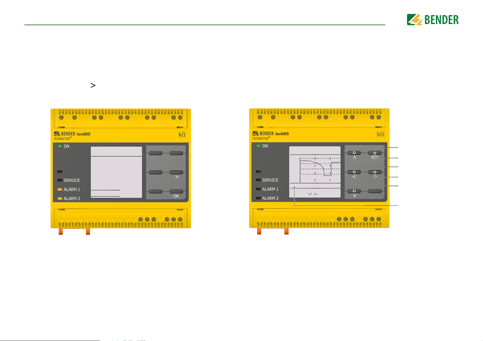
DisplayDisplay
RESET 3.2
Reset current
messages? All
messages are
saved in the
history memory.
Cancel RESET
PGH ON
1,0
,10 0
,010
,001
MΩ
Hour 16:26 16:52
Data-isoGraph 2
1/4
PGH ON
Change parameter value
Leave view
Modify scale
Modify scale
Change parameter value
Current time scale
8.4 Acknowledging a fault message
In order to acknowledge the fault message and return to the ISOMETER®'s standard display, all faults must be acknowledged by means of the reset button.
This means that fault messages can only be reset when the cause of the fault has been
eliminated.
Press the reset button, then and OK to clear the fault memory. The ISOMETER® then returns to the standard display.
8.5 Data - isoGraph
The isoGraph represents the chronological sequence of the insulation resistance over
time. This graphical representation can be displayed over the following time periods:
hour, day, week, month and year.
The measured values for individual representations are stored in a separate memory. Up
to 100 measured values are available to represent each graph. and the resolution of each
graph is determined by these values.
38
iso685-D-P_D00170_00_M_XXDE/06.2016
Page 39
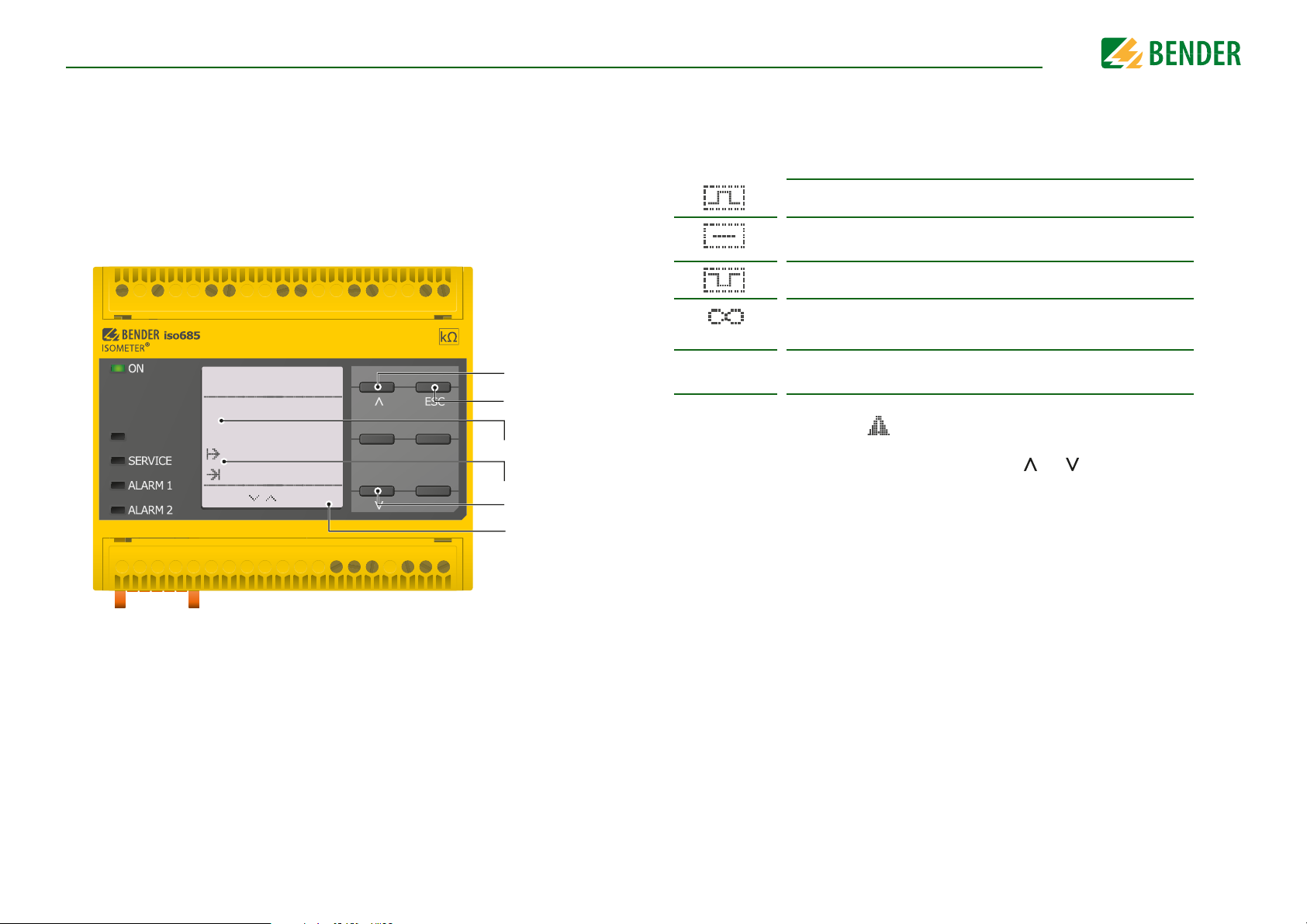
DisplayDisplay
History 4.1
Insulation fault
11kΩ
28.0 3.14 17:0 2
28.03.14 17:18
8/8
PGH ON
Next message
Leave view
8.6 History memory
Up to 1023 alarm messages and device errors are stored in the history memory with date
and time stamp. When the history memory is deleted, the minimum insulation resistance
will also be reset at Menu/Data Measured values - Data insulation.
R
min
Fault description
Alarm value
Feault occured
Fault disappeared
Previous message
Number of selected
errors/
Total number of
error messages
8.7 Insulation fault location
When EDS mode is activated, the ISOMETER® indicates the message "Ins. fault locat.". Below, on the left side it indicates which EDS mode is activated. On the right side it indicates
the polarity change of the measuring pulses including the pause in between .
Positive measuring pulse
Pause
Negative measuring pulse
The insulation fault location has been started manually and runs continuously.
No insulation measurement takes place.
43 s
An active fault is displayed by . The upper part of the display will become orange and
displays the fault message. The alarm LEDs are lit. If several fault messages have appeared, you can navigate through the faults using the and buttons.
Insulation fault location in auto mode and 1 cycle.
Time countdown of a measurement cycle.
39
iso685-D-P_D00170_00_M_XXDE/06.2016
Page 40
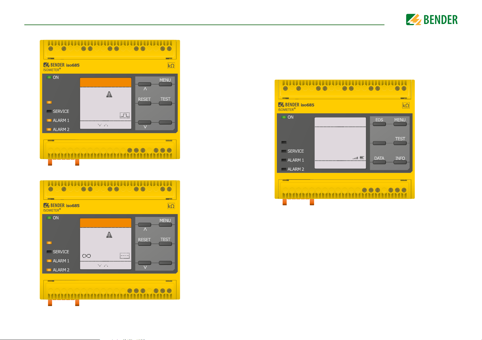
DisplayDisplay
IT-System
1x
1/2
1x
Fault locationFault location
43 s
PGH ON
IT-System
1x
1/2
1x
Fault locationFault location
s
PGH ON
IT System
Initial
measurement
Initial
measurement
R(an) 40kΩ/10kΩ
PGH ON
Insulation fault location in auto mode and 1 cycle.
Insulation fault location has been started manually.
8.8 Initial measurement
During the initial measurement, the device records all measured values.
All measured values that may have been recorded before will be discarded if a new initial
measurement is started.
40
iso685-D-P_D00170_00_M_XXDE/06.2016
Page 41
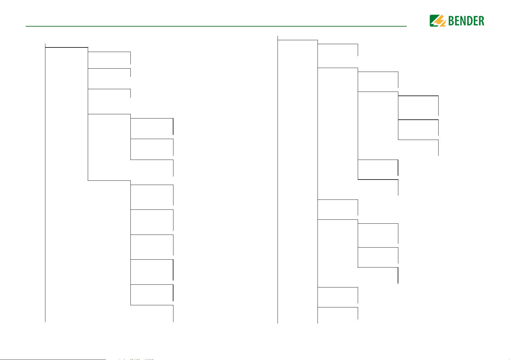
9. Menu
Menu
9.1 Menu structure
1. Alarm settings
1. Insulation Alarm
2. DC alarm
3. Profile
4. System type
5. ISOnet
6. Device
7. T(start)
8. Coupling monitoring
9. Inputs
10. Outputs
1. Alarm 1
2. Alarm 2
3. Memory
1. Alarm
2. U(DC-E)
1. ISOnet
2. Number of devices
1. Digital 1
2. Digital 2
3. Digital 3
1. Relay 1
2. Relay 2
3. Digital 1
4. Digital 2
5. Buzzer
6. Analog
1. Mode
2. t(on)
3. t(off)
4. Function
1. Mode
2. t(on)
3. t(off)
4. Function
1. Mode
2. t(on)
3. t(off)
4. Function
1. TEST
2. Relay mode
3. Function 1
4. Function 2
5. Function 3
1. TEST
2. Relay mode
3. Function 1
4. Function 2
5. Function 3
1. TEST
2. Mode
3. Function 1
4. Function 2
5. Function 3
1. TEST
2. Mode
3. Function 1
4. Function 2
5. Function 3
1. TEST
2. Function 1
3. Function 2
4. Function 3
1. Mode
2. Scale centre
3. TEST
4. Function
2. EDS
1. General
2. Scan for channels
3. Enable channel
4. Group settings
5. Channel
6. Outputs
7. Inputs
8. Device
9. Service
1. Current
2. Mode
2. Use portable EDS
1. Channel
2. Outputs
3. Digital Input
4. Device settings
1. Name
2. CT monitor
3. I∆L Response value
4. I∆n Response value
1. Relay
2. Buzzer
3. Digital Output
1. Mode
2. t(on)
3. t(off)
4. Function
1. Name
2. Trigger
3. Fault memory
1. CT
2. CT monitor
3. I∆L Response value
4. I∆n Response value
1. Relay
2. Buzzer
3. Digital Output
1. Mode
2. t(on)
3. t(off)
4. Function
1. System type
2. Frequency
3. Trigger
4. Fault memory
1. TEST
2. Relay mode
3. Function 1
4. Function 2
5. Function 3
1. TEST
2. Function 1
3. Function 2
4. Function 3
1. TEST
2. Function 1
3. Function 2
4. Function 3
1. TEST
2. Relay mode
3. Function 1
4. Function 2
5. Function 3
1. TEST
2. Function 1
3. Function 2
4. Function 3
1. TEST
2. Function 1
3. Function 2
4. Function 3
41
iso685-D-P_D00170_00_M_XXDE/06.2016
Page 42

3. Data measured values
Current
6.6.9
o 1mA
o 1.8mA
o 2.5mA
o 5mA
• 10mA
Date 5.2.4
14.01.2014
min. 1
max. 31
Ethernet 6.3.2
-.0123456789abcdef
ghijklmnopqrstuvwx
yz del
4. Cont rol
5. Histor y
6. Device settings
7. Info
1. Language
2. Clock
3. Inter face
4. Display
5. Password
6. Commissioning
7. Backup
8. Service
1. Time
2. Format
3. Summertime
4. Date
5. Format
6. NTP
7. NTP Servier
8. UTC
1. Write access
2. Ethernet
3. BCOM
4. Modbus TCP
5. BS bus
1. Brightness
1. Password
2. Status
1. DHCP
2. IP
3. SN
4. Std. GW
5. DNS-Server
6. Domain
1. Systemname
2. Subsystem
3. Device Address
4. Timeout
5. TTL for Subscription
1. Port 502
1. Address
MenuMenu
9.2 Operating and navigating
Navigate through the device menu using the device buttons. The functions of the device
buttons are described in the chapter “Display elements and device buttons” on page 18.
9.2.1 Easy operation
Navigation in lists
To make a selection in a list, navigate using
the and buttons to the required
menu item. Then click "OK".
Navigation with arrows
You can increase or decrease a value using
the and buttons. You can move to
the left or the right to set different values
using the and buttons. The value positioned between the symbols is the value that is set.
Text input
Go step by step through the numbers and
letters indicated on the display by using
the button (forwards) and the button
(backwards). Navigate to the right using
the button to enter the next character.
To delete a character that has been entered, use the and buttons to navigate to the character to be deleted and
then select "del" using the and buttons.
Confirm the entered text with "OK".
The menu structure may vary when different EDS types are connected.
42
iso685-D-P_D00170_00_M_XXDE/06.2016
Page 43
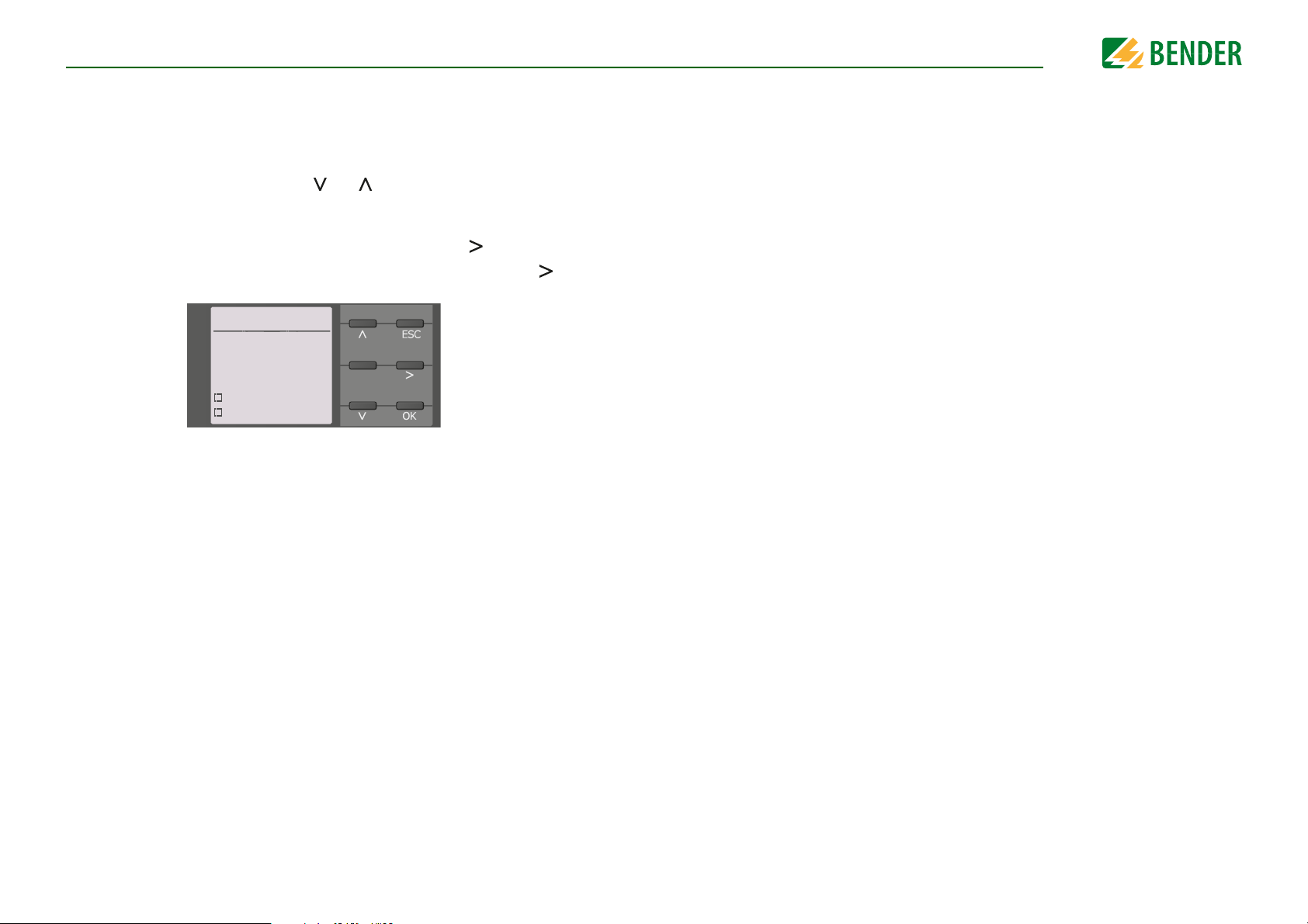
9.2.2 Multiple selection in the device menu
Activating channels 2.3
Select all
No selection
Invert selection
Channel 1
Channel 2
At some points in the menu, you can select several channels, relays, etc. at a time. Thereby, you can make settings for several selection points simultaneously.
Select 1…n selection points using the and buttons. Each selection in the list must
be confirmed with "OK".
If you have made your selection, there are two options depending on the menu item:
• Navigating to the settings for the previous selection using .
• Initiating the respective action (e.g. activate selected channels) using .
MenuMenu
43
iso685-D-P_D00170_00_M_XXDE/06.2016
Page 44
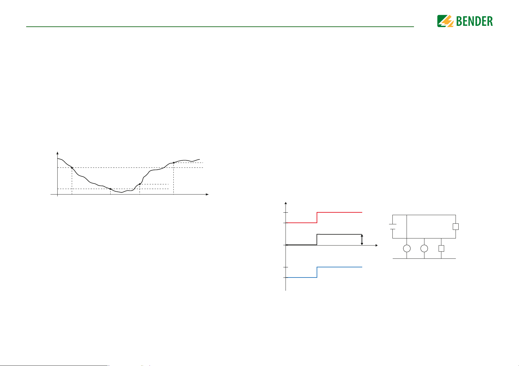
10. Settings
120 V
t
V
DC+
DC-
100 V
200 V
0 V
-80 V
-100 V
R
f
R
f
U1
U1
U2
U2
U
DC-E
=(U1+U2)/2=(120 V-80 V)/2=20 V
U
DC-E
Settings
10.1 Settings in the device menu
The settings of the ISOMETER® are explained in the order of the device menu.
10.1 1.0 Alarm settings
The limit values for the insulation resistances of alarm 1 and alarm 2 can be specified in
the alarm settings menu and can be adapted to the user profile of the ISOMETER®. A device password is required for entering the settings. You can adjust the following functions:
10.1 1.1 Insulation alarm
In the Insulation alarm menu, the ISOMETER® limit values for alarm 1 and alarm 2 can be
set.
Activation or deactivation of the two alarm levels R
(alarm 1) and R
an1
lustrated in the following graphic:
An alarm will become inactive as soon as the hysteresis of the set operating value is exceeded.
R
Alarm 1
inactive
hysteresis
R
an1
R
an2
Alarm 1
active
Alarm 2
active
hysteresis
Alarm 2
inactive
10.1 1.1.1 Alarm 1
For alarm 1 an insulation resistance of 1 kΩ…10 MΩ can be set irrespective of alarm 2.
(alarm 2) are il-
an2
t
10.1 1.1.3 Fault memory
Automatic reset of inactive faults at the outputs relay 1, relay 2, digital output 1, digital
output 2:
•on
•off
If a fault becomes inactive, the programmed outputs remain
in fault condition until they are reset manually.
If a fault becomes inactive, the programmed outputs automatically change the state.
10.1 1.2 DC alarm
The DC alarm is triggered in the event of a DC offset voltage (U
) in the system.
DC-E
10.1 1.2.1 Alarm
•on
•off
The DC alarm is triggered in the event of a DC offset voltage.
The DC alarm is NOT triggered in the event of a DC offset
voltage.
10.1 1.2.2 U(DC-E)
Set the DC alarm to a value between 20 V and 1 kV.
10.1 1.1.2 Alarm 2
For alarm 2 an insulation resistance of 1 kΩ…10 MΩ can be set irrespective of alarm 1.
44
iso685-D-P_D00170_00_M_XXDE/06.2016
Page 45

SettingsSettings
10.1 1.3 Profile
Adapt the area of application of the ISOMETER® to your system profile. For a description
of the profiles, refer to “Device profiles” on page 73.
The following can be selected:
•Power circuits
•Control circuits
•Generator
•High capacitance
•Inverter > 10 Hz
•Inverter < 10 Hz
Suitable for most IT systems.
Not recommended for voltages > 230 V.
Fast measuring times, fast fault location possible.
Suitable for system with high leakage capacitances.
Suitable for systems with dynamic frequency control by
inverters in the range 10 to 460 Hz.
Suitable for systems with extremely low frequency control
in the range 1…460 Hz.
10.1 1.4 System type
Adapt the ISOMETER® to the IT system to be monitored. The following can be selected:
•DC
•AC
•3AC
DC system
(refer to “Connection to a DC system” on page 30)
Single-phase AC system
(refer to “Connection to an AC system” on page 29)
3AC system
(refer to “Connection to a 3(N)AC system” on page 28)
10.1 1.5 ISOnet
Make the settings to use the ISONet function.
The ISOnet function ensures via the Ethernet connection that only one ISOMETER® of the
interconnection is active when several ISOMETER®s are connected to an IT system.
For further information regarding the ISOnet function, refer to “System isolation via ISOn-
et” from page 71.
10.1 1.5.1 ISOnet
Activate or deactivate the ISONet function
•off
•BCOM
The ISOnet is deactivated
The ISOnet function is activated via BCOM
10.1 1.5.2 Number of devices
Configure the number of devices (2…20) in a subsystem.
10.1 1.6 Device
Set the ISOMETER® insulation resistance measurement function to active or inactive:
•Active
•Inactive
10.1 1.7 T(Start)
The device is active.
The device DOES NOT measure the insulation resistance, the
message Device inactive appears on the display. The
IT system is NOT being monitored!
The ISOMETER® can be operated with a start-up delay of 0…120 seconds. The start-up is
delayed until the initial measurement takes place.
10.1 1.8 Coupling monitoring
The ISOMETER® continuously monitors the coupling of energised systems. The coupling
of de-energised systems is monitored at 8-hour intervals. This monitoring function can be
activated or deactivated.
•on
•off
Coupling monitoring is activated.
Coupling monitoring is deactivated.
45
iso685-D-P_D00170_00_M_XXDE/06.2016
Page 46
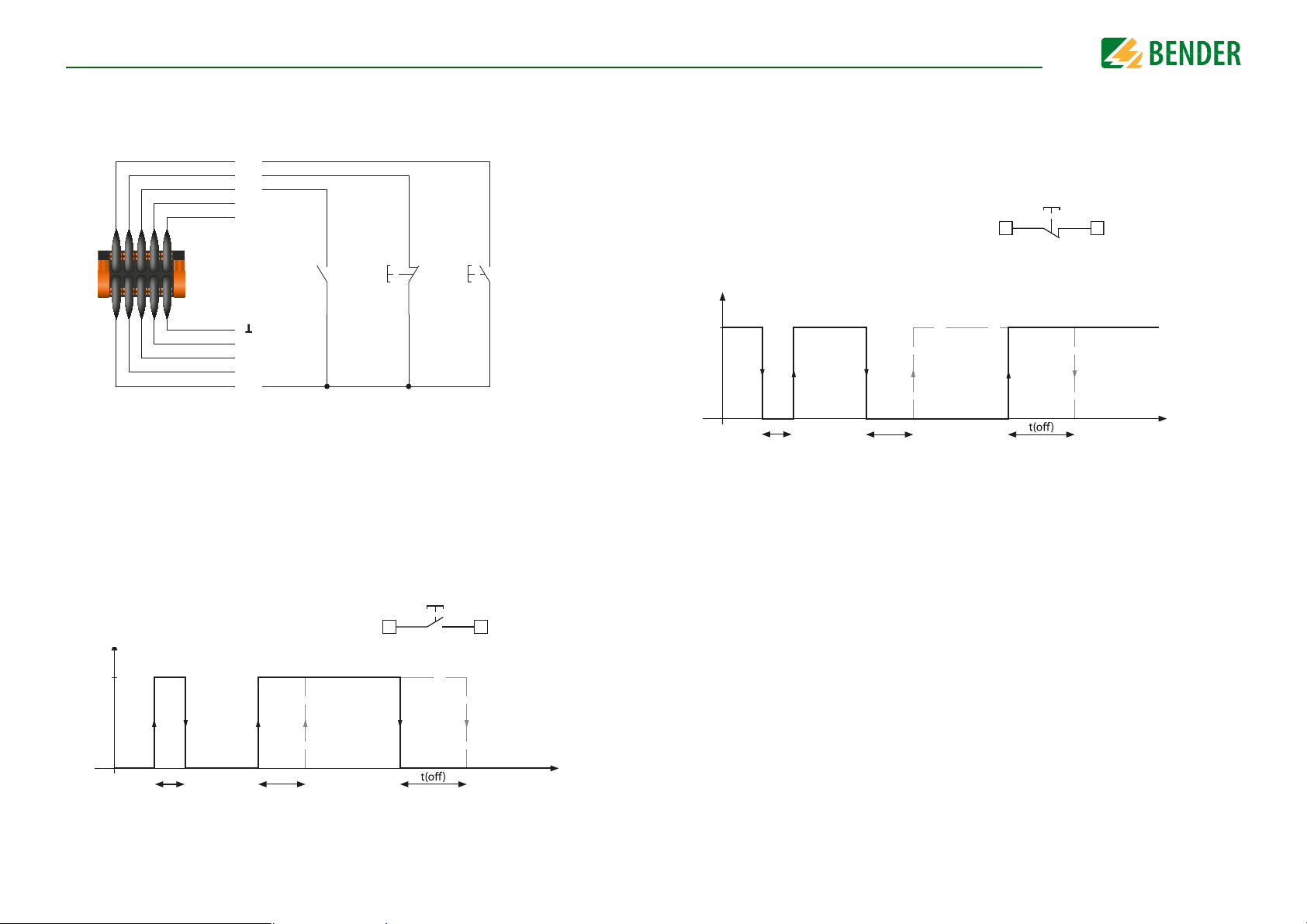
10.1 1.9 Inputs
I2
I3
A
B
M+
Q2
Q1
+
Device
inactive
Reset Test
I1
t
0
1
t(on)
Reaction
Impulse on
Reaction
Impulse o
t
0
1
t(on)
Reaction Reaction
Impulse onImpulse o
The ISOMETER® provides a total of three digital inputs.
The exemplary wiring diagram shows how the digital inputs can be wired:
SettingsSettings
•Active low
An event is carried out on the falling edge of the
digital input (high to low).
Response time t(on)/t(off) after a switch-off signal.
X1 X1
+I
x
10.1 1.9.1 Digital 1
The following parameters can be set for the digital input:
10.1 1.9.1.1 Mode
The operating mode for the digital input can be set to the following values:
10.1 1.9.1.2 t(on)
The response time t(on) after a switch-on signal can be set between 100 milliseconds and
< t(on)
300 seconds (refer to “10.1 1.9.1.1 Mode”).
•Active high
< t(on)
46
An event is carried out on the rising edge of the
digital input (low to high).
Response time t(on)/t(off) after a switch-on signal.
X1 X1
+I
x
10.1 1.9.1.3 t(off)
The response time t(off) after a switch-off signal can be set between 100 milliseconds and
300 seconds (refer to “10.1 1.9.1.1 Mode”).
iso685-D-P_D00170_00_M_XXDE/06.2016
Page 47
SettingsSettings
≥ 1
Response
Function 1
Function 2
Function 3
10.1 1.9.1.4 Function
The parameters for the function of the digital inputs of the ISOMETER® can be set differently:
•off
•TEST
•RESET
•Deactivate device
•Start initial measurement
•Insulation fault location
Digital input without function
Device self test
Reset of fault and alarm messages
The device DOES NOT measure the insulation
resistance, the message
appears on the display.
The IT system is NOT being monitored!
The device uncouples itself from the system to
be monitored through an internal system isolating switch.
All recorded measurements are discarded and a
new measurement is started
The insulation fault location is started.
Device inactive
10.1 1.9.2 Digital 2
Refer to “10.1 1.9.1 Digital 1”.
10.1 1.9.3 Digital 3
Refer to “10.1 1.9.1 Digital 1”.
10.1 1.10 Outputs
The ISOMETER® provides a total of six outputs.
The following parameters can be set for the outputs:
10.1 1.10.1 Relay 1
The following parameters can be set for each relay:
10.1 1.10.1.1 TEST
The functional test of the relay can be activated or deactivated. This only applies to the
manual test and not to the cyclic device self test:
•on
•off
The manual test checks the switching function of the relay
The manual test does not check the switching function of
the relay
10.1 1.10.1.2 Relay operating mode
The relay mode can be adapted to the application:
•N/C
•N/O
Normally closed- N/C operation contacts11-12-14 / 21-2224 (in fault-free condition, the alarm relay is energised).
Normally opened - N/O operation contacts
(in fault-free condition, the alarm relay is de-energised).
11-12-14 /
21-22-24
10.1 1.10.1.3 Function 1
Up to three functions can be assigned to one output. The functions are linked to an OR
operator:
47
iso685-D-P_D00170_00_M_XXDE/06.2016
Page 48

SettingsSettings
DC+ alarm
Symmetrical alarm
DC- alarm
0 %
25 %
50 %
75 %
100 %
Select the appropriate setting for function 1. The following parameters can be set.
•off
•Ins. Alarm 1
•Ins. Alarm 2
•Connection fault
•DC alarm
•DC+ alarm
The function is not used.
The status of the output changes when the value falls
below the set response value R
The status of the output changes when the value falls
below the set response value R
The status of the output changes when one of the following connection fault occurs:
• No low-resistance connection between the line conductors.
• No low-resistance connection between the terminals E
and KE to earth (PE).
• The load connected to the current output is too low
• The load connected to the current output is too high.
• Load on X1 too high.
The status of the output changes in case of an earth fault
in the direction of DC when 75 % of the value are
exceeded. This does not concern symmetrical faults. This
function will only be carried out when the value falls
below the response value R
tem voltage is U
The status of the output changes in case of an earth fault
in the direction of DC+ when 25 % of the value are
exceeded. This does not concern symmetrical faults. This
function will only be carried out when the value falls
below the response value R
tem voltage is U
≥ 50 V.
n
≥ 50 V.
n
an1.
an2.
and when the nominal sys-
an1
and when the nominal sys-
an1
•Common alarm
•Measurement complete
•Device inactive
•DC offset alarm
•Common alarm EDS
The status of the output changes on the occurrence of any
alarm and fault messages
(Ins. alarm 1 & 2, DC- / DC+ alarm, symmetrical alarm, connection and device faults).
The status of the output changes at the end of the initial
measurement.
The status of the output changes when the device has
been deactivated via a digital input or the control menu.
The status of the output changes on the occurrence of a
DC offset voltage in the system.
The status of the output changes on the occurrence of any
message triggered by the EDS.
10.1 1.10.1.4 Function 2
Refer to “10.1 1.10.1.3 Function 1”.
10.1 1.10.1.5 Function 3
Refer to “10.1 1.10.1.3 Function 1”.
10.1 1.10.2 Relay 2
Refer to “10.1 1.10.1 Relay 1”.
10.1 1.10.3 Digital 1
The following parameters can be set for each of the digital outputs:
•Symmetrical alarm
•Device fault
48
The status of the output changes in the event of a resistance ratio between DC+ and DC- of 25 % to 75 %.
The status of the output changes in the event of an internal device fault.
iso685-D-P_D00170_00_M_XXDE/06.2016
Page 49
SettingsSettings
10.1 1.10.3.1 TEST
The functional test of the digital output can be activated or deactivated. This only applies
to the manual test and not to the cyclic device self test:
•on
•off
The manual test changes the status of the digital output.
The manual test does not change the status of
the digital output.
10.1 1.10.3.2 Mode
The following settings can be used to set the operating mode for the digital output:
•Active
•Passive
In the active mode +24 V will be applied across
the output.
X1 X1
Q
x
In the passive mode the output of the applied
potential switches to ground.
X1 X1
+
Q
x
10.1 1.10.4 Digital 2
Refer to “10.1 1.10.3 Digital 1”.
10.1 1.10.5 Buzzer
The following parameters can be set for the buzzer:
10.1 1.10.5.1 TEST
The functional test of the buzzer can be activated or deactivated. This only applies to the
manual test and not to the cyclic device self test:
•on
•off
The manual test activates the buzzer sound.
The manual test does not activate the buzzer
sound.
10.1 1.10.5.2 Function 1
Refer to “10.1 1.10.1.3 Function 1”.
10.1 1.10.5.3 Function 2
Refer to “10.1 1.10.1.3 Function 1”.
10.1 1.10.5.4 Function 3
Refer to “10.1 1.10.1.3 Function 1”.
Observe the maximum output current!
Maximum output current in case of internal voltage supply
via A1/+ and A2/-: 200 mA in total to X1.
10.1 1.10.3.3 Function 1
Refer to “10.1 1.10.1.3 Function 1”.
10.1 1.10.3.4 Function 2
Refer to “10.1 1.10.1.3 Function 1”.
10.1 1.10.3.5 Function 3
Refer to “10.1 1.10.1.3 Function 1”.
49
iso685-D-P_D00170_00_M_XXDE/06.2016
Page 50
SettingsSettings
M
+
X1 X1
A
M
+
X1 X1
V
I/U20 mA / 400 µA
10 V
0 mA / 4 mA
0 V / 2 V
1 k
1 M
100
100 k
Ω
28 kΩ
120 kΩ
I/U20 mA / 400 µA
10 V
0 mA / 4 mA
0 V / 2 V
120 kΩ28 kΩ
RF =
(A2 - A1) * R
SKM
- R
SKM
A
3
- A
1
R
SKM
= 28 kΩ or 120 kΩ/midscale
A3= Measured value analogue output
R
F
= Insulation fault in kΩ
10.1 1.10.6 Analogue
The following parameters can be set for the analogue output:
10.1 1.10.6.1 Mode
The following values can be set for the operating mode of the analogue output
Current output
•0-20 mA
•4-20 mA
•0-400
μA
Permissible load ≤ 600 Ω
Permissible load ≤ 600 Ω
Permissible load ≤ 4 kΩ
Voltage output
•0-10 V
•2-10 V
Permissible load ≥ 1 kΩ
Permissible load ≥ 1 kΩ
10.1 1.10.6.2 Midscale
Select the appropriate midscale. The following parameters can be set:
•Linear
•28 k
Ω
•120 k
Ω
The switching signal is linear to the insulation resistance in
the indicated measuring range.
The switching signal is analogue to the mid scale of 28 kΩ
or 120 kΩ on a measuring instrument.
Calculation of the insulation resistance using the analogue output:
50
Lower value
Analogue output A
0 mA
4 mA
0 µA
0 V
2 V
iso685-D-P_D00170_00_M_XXDE/06.2016
Upper value
Analogue output A
1
20 mA
20 mA
400 µA
10 V
10 V
2
Page 51
SettingsSettings
DC+ alarm
Symmetrical alarm
DC- alarm
0 %
25 %
50 %
75 %
100 %
0 V/2 V
0 mA/4 mA
0 µA
10 V
20 mA
400 µA
CAUTION
10.1 1.10.6.3 TEST
The functional test of the analogue output can be activated or deactivated. In this way,
the analogue output is adjusted once for the entire range. This only applies to the manual
test and not to the cyclic device self test:
•on
•off
The manual test checks the analogue output
function.
The manual test does not check the analogue
output function.
10.1 1.10.6.4 Function
Select the appropriate setting for the analogue output. The following parameters can be
set.
•Insulation value
•DC offset
Depending on the measured insulation value,
an analogue current or voltage signal is provided at the output.
Depending on the measured DC offset, an analogue current or voltage signal is provided at
the output. This setting can only be used when
Linear is selected in the menu "Midscale".
10.1 2.0 EDS (insulation fault location)
10.1 2.1 General
10.1 2.1.1 Current
Risk of malfunctions due to excessive locating current on sensitive
system parts!
The locating current flowing between the IT system and earth can cause
controller faults in sensitive parts of the system, such as the PLC or relay.
Ensure that the level of the locating current is compatible with the system
to be monitored.
Set the maximum locating current in the ISOMETER®. You can find the device-specific
maximum locating currents in the table below.
•1 mA
•1.8 mA
•2.5 mA
•5 mA
•10 mA
for EDS441…
for EDS441…
for EDS441…
for EDS441…, EDS440…
for EDS440…
51
•25 mA
•50 mA
for EDS440…
for EDS440…
iso685-D-P_D00170_00_M_XXDE/06.2016
Page 52
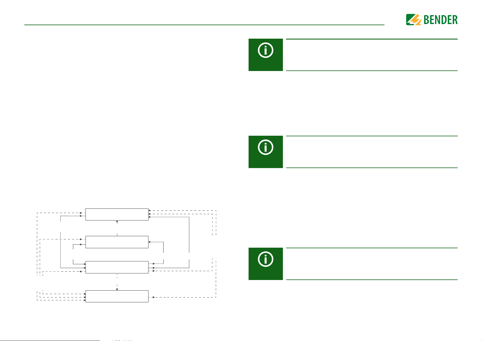
10.1 2.1.2 Mode
Inactive insulation fault location
(insulation measurement)
Active insulation fault location
for 1 cycle
Insulation fault location pauses
(insulation measurement)
Active insulation fault location
continuously
New insulation fault
Mode: auto/1 cycle
No insulation fault
Insulation fault
still present
Manual start
Manual start.
The device retains the
original mode setting
Manual stop.
The device retains the
original mode setting
Mode: 1 cycle
Mode: auto
To locate insulation faults, select one of the three available modes for insulation fault
location.
•Manual
•auto
•1 cycle
In manual mode, the insulation fault location does not start
automatically. If you start the insulation fault location, it
remains active without considering the insulation resistance
and the alarm message of the ISOMETER®.
In auto mode, the insulation fault location starts automatically as soon as the response value of alarm 2 of the
ISOMETER® has fallen below the preset value. The insulation
fault location is cyclically interrupted for an insulation measurement. If the insulation fault still exists after the interruption, the insulation fault location starts again. The insulation
fault location only stops if alarm 2 is inactive. If a new insulation fault appears, the insulation fault location restarts automatically.
In 1-cycle mode, the insulation fault location starts automatically as soon as the response value of alarm 2 of the
ISOMETER® has fallen below the preset value. The insulation
fault location is stopped after one cycle.
If the insulation fault still exists after the interruption, the
insulation fault location does NOT start again. If a new insulation fault appears, the insulation fault location restarts
automatically for one cycle.
SettingsSettings
Do not carry out a manual test during a manually started insulation fault
location, since the insulation fault location would be aborted by that.
10.1 2.1.3 Using a portable EDS
If you would like to use a portable EDS, activate this function here. After that, the insulation fault location process will be automatically adjusted.
•on
•off
Insulation faults can be located with a portable EDS.
Insulation faults cannot be located with a portable EDS
If the trigger mode is set to "auto", the use of a portable EDS must be activated in the menu as the measurement method is correspondingly adjusted at this menu point (also refer to “10.1 2.4.4.3 Trigger”).
10.1 2.2 Scanning channels
For a successful insulation fault location, all active measuring channels must be determined. Indicate if you would like to start the search for EDS measuring channels.
52
•Cancel
•Start
Aborts the scan process.
Starts the scan process (search) for EDS channels.
Also refer to “Commissioning EDS” on page 35.
If one bus device fails, the ISOMETER® asks whether it should search for
measuring channels and then automatically determines all channels
again. Also refer to
“Alarm messages” from page 78
.
iso685-D-P_D00170_00_M_XXDE/06.2016
Page 53

SettingsSettings
10.1 2.3 Activating channels
During initial commissioning all channels are inactive. Before configuring the channels
they must be activated in this menu.
Select which measuring channels you would like to activate. Multiple selection is possible
here.
•Select all
•No selection
•Invert selection
•Channel 1(BS 2/1)
All measuring channels are selected.
No channel is selected.
The current selection is inverted.
A single channel is selected.
…
•Channel 12 (BS 2/
12)
Navigate to the required selection point using the and buttons. Confirm your selection by pressing "OK". The selected channels are activated with the button.
10.1 2.4 Group settings
Use group settings to adjust the settings for several EDS or EDS channels simultaneously
or to read out settings.
If you would like to make settings for each EDS or each EDS channel individually, then
please refer to the menus from “10.1 2.5 Channel” to “10.1 2.8 Device”.
10.1 2.4.1 Channel
Before configuring a measuring channel, you must activate it.
Select which measuring channel you would like to activate and configure.
•Select all
•No selection
•Invert selection
•Channel 1 (BS 2/1)
All measuring channels are selected.
No channel is selected.
The current selection is inverted.
A single channel is selected.
•Channel 2 (BS 2/2)
•Channel 3 (BS 2/3)
Navigate to the required selection point using the and buttons. Confirm your selection by pressing "OK". Activate the selected measuring channel using the button
and navigate to its setting options.
10.1 2.4.1.1 Current transformer (CT)
Set the used current transformer.
•Type A
•Type AB
W…/WR…/WS…/
W/WS8000
W…A B
53
The values indicated in the group settings are not the values of the individual EDS but the factory settings or the last adjusted values in the
ISOMETER®. To see the values of the individual EDS, please navigate to the
menu points “10.1 2.5 Channel” to “10.1 2.8 Device”.
10.1 2.4.1.2 CT monitoring
Activate or deactivate the CT monitoring.
If CT monitoring is active, an alarm is signalled as soon as a fault occurs on a current transformer of an activated channel (short circuit or interruption).
•on
•off
CT monitoring is activated
(the current transformers are monitored).
CT monitoring is deactivated (the current transformers
are not monitored).
iso685-D-P_D00170_00_M_XXDE/06.2016
Page 54
SettingsSettings
CAUTION
CAUTION
10.1 2.4.1.3 IΔL Response value
Set the response value for I
(main alarm for insulation fault location) between 200 µA
∆L
and 10 mA. The response value must be below the set locating current
(refer to 7.2.6 “Setting EDS current” on page 34
).
The permissible response value and the response sensitivity depend on
the connected EDS (EDS440… or EDS441…).
10.1 2.4.1.4 IΔn Response value
Set the response value for I
(alarm for residual current measurement) between 100 mA
∆n
and 10 A.
The permissible response value and the response sensitivity depend on
the connected EDS (EDS440… or EDS441…).
10.1 2.4.2 Outputs
In this menu, the settings for the outputs of the EDS can be made.
•Relays
10.1 2.4.2.1 Relays
Select the relays that you would like to configure.
•Select all
•No selection
•Invert selection
•Relay 1 (BS 2/1)
All relays are selected.
No relay is selected.
The current selection is inverted.
A single relay is selected.
•Relay 2 (BS 2/2)
10.1 2.4.2.1.1 TEST
The functional test of the relay can be activated or deactivated. This only applies to the
manual test and not to the cyclic device self test.
•on
•off
The manual test checks the switching function of the
relay.
The manual test does not check the switching function
of the relay.
10.1 2.4.2.1.2 Operating mode
The relay operating mode can be adapted to the application.
•Buzzer
•Dig. output
54
•N/C
•N/O
Normally closed- N/C operation contacts11-12-14 / 21-2224 (in fault-free condition, the alarm relay is energised).
Normally opened - N/O operation contacts 11-12-14 / 21-2224 (in fault-free condition, the alarm relay is de-energised).
iso685-D-P_D00170_00_M_XXDE/06.2016
Page 55

SettingsSettings
≥ 1
Response
Function 1
Function 2
Function 3
10.1 2.4.2.1.3 Function 1
Up to three functions can be assigned to one output. The functions are linked to an OR
operator:
Set the function for the outputs:
•off
•I
ΔL
•I
ΔN
•Device fault
•Connection fault
•Insulation fault
location active
The function is not used.
The status of the output changes if an insulation fault is
detected (EDS function) on one of the measuring channels.
The status of the output changes if the residual current
(RCM function) is exceeded.
The status of the output changes in the event of an internal device fault.
The status of the output changes when one of the following measuring current transformer connection faults
occurs:
• Measuring current transformer defective
• Power supply cable interrupted
• Power supply cable short-circuited
The buzzer signals active insulation fault location
can only be set for buzzer).
10.1 2.4.2.2 Buzzer
Select the buzzers that you would like to configure.
•Select all
•No selection
•Invert selection
•Buzzer 1 (BS 2/1)
All buzzers are selected.
No buzzer is selected.
The current selection is inverted.
A single buzzer is selected.
Now assign the events on which the buzzers should be triggered.
10.1 2.4.2.2.1 TEST
Refer to “10.1 2.4.2.1.1 TEST”.
10.1 2.4.2.2.2 Function 1
Refer to “10.1 2.4.2.1.3 Function 1”.
10.1 2.4.2.2.3 Function 2
Refer to “10.1 2.4.2.1.3 Function 1”.
10.1 2.4.2.2.4 Function 3
Refer to “10.1 2.4.2.1.3 Function 1”.
10.1 2.4.2.3 Digital output
Select the digital outputs of the EDS that you would like to configure.
•Select all
•No selection
•Invert selection
All digital outputs are selected.
No digital output is selected.
The current selection is inverted.
•Common alarm
The status of the output changes on the occurrence of any
alarms and fault messages (I∆L alarm, I∆n alarm, connec-
tion and device fault).
10.1 2.4.2.1.4 Function 2
Refer to “10.1 2.4.2.1.3 Function 1”.
10.1 2.4.2.1.5 Function 3
Refer to “10.1 2.4.2.1.3 Function 1”.
55
•Dig. output 1 (BS 2/1)
A single digital output is selected.
Now make the settings for the digital outputs of the EDS selected before.
iso685-D-P_D00170_00_M_XXDE/06.2016
Page 56

SettingsSettings
10.1 2.4.2.3.1 TEST
The functional test of the digital output can be activated or deactivated. This only applies
to the manual test and not to the cyclic device self test:
•on
•off
The manual test changes the status of the digital output.
The manual test does not change the status of
the digital output.
10.1 2.4.2.4 Function 1
Refer to “10.1 2.4.2.1.3 Function 1”.
10.1 2.4.2.5 Function 2
Refer to “10.1 2.4.2.1.3 Function 1”.
10.1 2.4.2.6 Function 3
Refer to “10.1 2.4.2.1.3 Function 1”.
10.1 2.4.3 Dig. input
Select the digital inputs of the EDS that you would like to configure:
•Select all
•No selection
All digital inputs are selected.
No digital input is selected.
10.1 2.4.3.1 Mode
The operating mode for the digital input can be set to the following values. For a description of the operating modes, refer to “Mode” on page 46. The following can be selected
•Active high
•Active low
An event is carried out on the rising edge of the digital
input (low to high).
An event is carried out on the falling edge of the digital
input (high to low).
10.1 2.4.3.2 t(on)
The response time t(on) after a switch-on signal can be set between 100 milliseconds and
300 seconds. For a description of the operating modes, refer to “Mode” on page 46.
10.1 2.4.3.3 t(off)
The response time t(off) after a switch-off signal can be set between 100 milliseconds and
300 seconds. For a description of the operating modes, refer to “Mode” on page 46.
10.1 2.4.3.4 Function
•off
•TEST
•RESET
Digital input without function.
Device self test.
Reset of fault and alarm messages.
:
•Invert selection
•Dig. input 1 (BS 2/1)
The current selection is inverted.
A single digital input is selected.
•Dig. input 2 (BS 2/2)
Now make the settings for the digital inputs of the EDS selected before.
56
10.1 2.4.4 Device settings
•Select all
•No selection
•Invert selection
•BS bus 2 (1-12)
All devices are selected.
No device is selected.
The current selection is inverted.
iso685-D-P_D00170_00_M_XXDE/06.2016
Page 57

SettingsSettings
10.1 2.4.4.1 System type
Settings made to this menu point will only have an effect on connected
EDS460 and NOT on EDS44… devices.
Adjust the EDS to the IT system to be monitored.
•DC
•AC
•3AC
DC system
Single-phase AC system
3AC system
10.1 2.4.4.2 Frequency
Settings made to this menu point will only have an effect on connected
EDS460 and NOT on EDS44… devices.
Configure the mains frequency of the IT system to be monitored.
•50 Hz
•60 Hz
•400 Hz
•DC
10.1 2.4.4.3 Trigger
The locating current pulse of the ISOMETER® is synchronised with the measurement technology in the EDS via the BB bus or the BS bus. This allows a more reliable detection of the
locating current pulse in the event of disturbances.
Disturbances can be caused e.g. by variable-speed drives, rectifiers, actuators, noise filters, PLCs, or control electronics.
•Com
•auto
Synchronisation via BS bus or BB bus. The EDS only searches for
insulation faults if the insulation fault location has been started.
Less time is needed for the insulation fault location as with the setting "auto".
No synchronisation (e.g. if there is no BS bus or BB bus).
The EDS continuously searches for insulation faults.
If the trigger mode is set to "auto", the use of a portable EDS must be activated in the menu
(menu item “10.1 2.1.3 Using a portable EDS” = "on"), since the measurement method is correspondingly adjusted at this menu point.
10.1 2.4.4.4 Fault memory
Faults that only occur temporarily can be saved.
•on
•off
After eliminating the cause of fault, alarm messages remain stored
until a RESET is carried out. This function applies to alarm and
device fault messages.
The EDS exits the alarm mode as soon as the cause of fault is eliminated.
57
10.1 2.5 Channel
In this menu, each channel can be configured. Also refer to “10.1 2.4.1 Channel”.
10.1 2.5.1 Name
Enter a name for the selected channel. This name will also be displayed on the gateways
and in the web server and can be edited via these as well.
iso685-D-P_D00170_00_M_XXDE/06.2016
Page 58

SettingsSettings
10.1 2.5.2 Current transformer monitoring
Refer to “10.1 2.4.1.2 CT monitoring”.
10.1 2.5.3 Response value I
ΔL
Refer to “10.1 2.4.1.3 I∆L Response value”.
10.1 2.5.4 Response value I
Δn
Refer to “10.1 2.4.1.4 I∆n Response value”.
10.1 2.6 Outputs
In this menu, each output can be configured. Also refer to “10.1 2.4.2 Outputs”.
10.1 2.6.1 Relays
Select the relay that you would like to configure.
•Relay 1 (BS 2/1)
...
10.1 2.6.1.1 TEST
Refer to “10.1 2.4.2.1.1 TEST”.
10.1 2.6.1.2 Operating mode
Refer to “10.1 2.4.2.1.2 Operating mode”.
10.1 2.6.1.3 Function 1
Refer to “10.1 2.4.2.1.3 Function 1”.
10.1 2.6.1.4 Function 2
Refer to “10.1 2.4.2.1.3 Function 1”.
10.1 2.6.1.5 Function 3
Refer to “10.1 2.4.2.1.3 Function 1”.
10.1 2.6.2 Buzzer
In this menu, each buzzer can be configured. Also refer to “10.1 2.4.2.2 Buzzer”.
10.1 2.6.2.1 TEST
Refer to “10.1 2.4.2.1.1 TEST”.
10.1 2.6.2.2 Function 1
Refer to “10.1 2.4.2.1.3 Function 1”.
10.1 2.6.2.3 Function 2
Refer to “10.1 2.4.2.1.3 Function 1”.
10.1 2.6.2.4 Function 3
Refer to “10.1 2.4.2.1.3 Function 1”.
10.1 2.6.3 Digital output
In this menu, each digital output can be configured.
Also refer to “10.1 2.4.2.3 Digital output”.
10.1 2.6.3.1 TEST
Refer to “10.1 2.4.2.3.1 TEST”.
10.1 2.6.3.2 Function 1
Refer to “10.1 2.4.2.1.3 Function 1”.
10.1 2.6.3.3 Function 2
Refer to “10.1 2.4.2.1.3 Function 1”.
10.1 2.6.3.4 Function 3
Refer to “10.1 2.4.2.1.3 Function 1”.
10.1 2.7 Inputs
In this menu, each digital input can be configured. Therefore, select a digital input.
•Dig. input 1 (BS 2/1)
•Dig. input 2 (BS 2/2)
10.1 2.7.1 Mode
Refer to “10.1 2.4.3.1 Mode”.
10.1 2.7.2 t(on)
Refer to“10.1 2.4.3.2 t(on)”.
10.1 2.7.3 t(off)
Refer to “10.1 2.4.3.3 t(off)”.
10.1 2.7.4 Function
Refer to “10.1 2.4.3.4 Function”.
58
iso685-D-P_D00170_00_M_XXDE/06.2016
Page 59

SettingsSettings
10.1 2.8 Device
10.1 2.8.1 Trigger
Refer to “10.1 2.4.4.3 Trigger”.
10.1 2.8.2 Fault memory
Refer to “10.1 2.4.4.4 Fault memory”.
10.1 2.9 Service
The service menu can only be accessed by Bender Service staff.
10.1 3.0 Data measured values
The ISOMETER® stores certain measured values for a specific period of time. You can view
these data at the "Data meas. values" menu point. Navigate through the different views
using the and buttons:
•isoGraph data
•Insulation data
•IT system data
•IT system data
•EDS data
•EDS data
Displays the insulation resistance and chronological sequence. See
on page 64.
Displays the current insulation resistance, the
minimum insulation resistance measured and
the system leakage capacitance.
Displays the system phase-to-phase voltages
and the mains frequency (r.m.s. values)
Displays the system phase-to-earth voltages
Displays
and buttons to switch between the two
options.
Displays the locating current for
Insulation fault location
I∆L and
“Device communication”
I∆n in % and ampere. Use the
10.1 4.0 Control
In the control menu, you can start a manual test reset, reset alarm messages and start an
initial measurement:
•TEST
•RESET
•Start initial measurement
•EDS
Manual device test
Reset of fault and alarm messages
All recorded measurements are discarded and a
new measurement is started
Starting and stopping the insulation fault location
10.1 5.0 History
In the history menu, the faults detected by the ISOMETER® are displayed. For a detailed
functional description, refer to “History memory” on page 39:
•History
•Delete
Overview of faults that have occurred
Reset the history memory
10.1 6.0 Device settings
The device settings menu allows you to configure the basic settings for the ISOMETER®:
10.1 6.1 Language
Choose the language to be displayed by the ISOMETER®. For example, you can set the languages:
•German
•English
59
•...
iso685-D-P_D00170_00_M_XXDE/06.2016
Page 60

SettingsSettings
10.1 6.2 Clock
In the clock menu you can set the display format of time and date for the ISOMETER®
iso685:
10.1 6.2.1 Time
Based on the selected time format you can set the current time to display 24-hour or 12hour notation (am/pm).
10.1 6.2.2 Format (time)
Select the appropriate time format to be displayed:
•12 h
•24 h
12-hour notation am/pm
24-hour notation
10.1 6.2.3 Summer time
Summer time can be considered in the following settings:
•off
•DST
•CEST
No automatic change between summer time and standard time.
Daylight Saving Time
Automatic change between summer and standard time according to North
American regulation.
North American summer time begins on each second Sunday in March at
02:00 local time by setting the clock forward by one hour from 2:00 to 03:00
local time. Summer time always ends the first Sunday in October at 03:00
local time by setting the clock back one hour from 3:00 to 2:00.
Central European Summer Time
Automatic change between summer time and standard time according to
Central European regulation.
Central European summer time begins on each last Sunday in March at
02:00 CEST by setting the clock forward by one hour from 2:00 to 03:00.
Central European summer time always ends on the last Sunday in October
at 03:00 CEST by setting the clock back one hour from 3:00 to 2:00.
10.1 6.2.4 Date
Based on the selected date format you can set the current date.
10.1 6.2.5 Format (date)
Select the appropriate date format you want to be displayed:
•dd.mm.yy
•mm-dd-yy
day, month, year
month, day, year
10.1 6.2.6 NTP
Select if you would like to synchronise the current time via NTP:
•on
•off
Synchronisation via NTP server is activated.
Synchronisation via NTP server is deactivated.
10.1 6.2.7 NTP server
Set NTP server.
10.1 6.2.8 UTC
Set the time according to UTC (coordinated world time). For Germany, set +1 for wintertime (MEZ) and +2 for summer time (MESZ).
10.1 6.3 Interface
Set the parameters for the connection of other devices to the ISOMETER® in the interface
menu:
60
When set to DST or CEST, changing between summer time and normal time
is only done on the date of the official time change.
iso685-D-P_D00170_00_M_XXDE/06.2016
Page 61

SettingsSettings
10.1 6.3.1 Write access
Set whether the device can be parameterised externally via Modbus or web server. Displaying and reading out data via Modbus and web server is always possible, regardless of
this setting.
•Allow
•Deny
Allow external parameter setting.
Refuse external parameter setting.
10.1 6.3.2 Ethernet
Set the parameters for communication with other devices via the Ethernet interface.
The Ethernet interface can be used for communication with Modbus, web server and
BCOM.
10.1 6.3.2.1 DHCP
Select whether you want to use automatic address assignment via your DHCP server:
•on
•off
Activate automatic IP address assignment.
Deactivate automatic IP address assignment.
10.1 6.3.2.2 IP
Set the appropriate IP address for the ISOMETER®.
10.1 6.3.2.3 SN
Set the appropriate subnet mask.
10.1 6.3.2.4 Std. GW
If a standard gateway is used, enter the IP address here. Ensure that the IP address of the
standard gateway suits the subnet mask, so that the ISOnet function can operate correctly.
10.1 6.3.2.5 DNS server
If a DNS server is used, enter the server's IP address.
10.1 6.3.3 BCOM
Set the parameters for communication with other devices via BCOM.
For further information, refer to “BCOM” on page 64.
10.1 6.3.3.1 System name
Set the system name of the network in which the devices are located. In order to guarantee that all devices are able to communicate via BCOM, all devices must have the same
system name.
10.1 6.3.3.2 Subsystem
Configure the subsystem address of the network in which the devices are located. The devices can communicate with subsystems with the same or different subsystem addresses.
EXCEPTION: In order to use the ISOnet functions, the devices must have the same subsystem address.
10.1 6.3.3.3 Device address
Assign a device address. Each device must have a different address to distinguish it from
another in the system and ensure correct communication.
10.1 6.3.3.4 Timeout
Set the timeout for messages between 100 ms…10 s.
This time specification defines the maximum permissible time for a device to respond.
When exceeding the timeout time in the ISOnet, the fault message "Failure address" is
shown.
10.1 6.3.3.5 TTL for subscription
Set a time between 1 s…1092 min.
This time defines the intervals at which the ISOMETER® sends messages to e.g. a gateway.
Severe alarms (e.g. insulation alarms or substantial value changes) are always sent immediately.
10.1 6.3.4 Modbus TCP
Settings for communication with other devices via Modbus TCP.
For further information, refer to “Modbus TCP” on page 64.
10.1 6.3.2.6 Domain
Enter the domain.
61
iso685-D-P_D00170_00_M_XXDE/06.2016
Page 62

SettingsSettings
10.1 6.3.4.1 Port 502
Choose whether Modbus TCP should be used:
•on
•off
Modbus TCP can be used for communication
with other devices.
Modbus TCP cannot be used for communication with other devices.
10.1 6.3.5 BS bus
Set the parameters for communication with other devices via the Bender sensor bus.
For further information, refer to “BS bus” on page 68.
10.1 6.3.5.1 Address
Select an address between 1 and 90 for the Bender sensor bus.
10.1 6.4 Display
Adjust the display brightness for the ISOMETER® in the display menu:
10.1 6.4.1 Brightness
Adjust the display brightness between 0 % and 100 % in steps of 10.
If no button is pressed on the display for 15 minutes, the brightness of the display is reduced. If now a button is pressed, the normal brightness is restored.
10.1 6.5 Password
Use the password function to protect the device parameters against unauthorised adjustment. The default password is 0000.
10.1 6.5.1 Password
Enter an individual four-digit password.
10.1 6.5.2 Status
Decide if the password query should be used:
•on
Password query active
10.1 6.6 Commissioning
In the commissioning menu you can open the ISOMETER®'s commissioning wizard again.
10.1 6.7 Data backup
In the data backup menu device settings can be saved or device settings already saved
can be restored.
•Save
•Restore
The ISOMETER® saves your device settings.
The ISOMETER® restores your initial device settings.
10.1 6.8 Service
The service menu can only be accessed by Bender Service staff.
10.1 7.0 Info
The ISOMETER®'s current settings can be viewed in the Info menu. Navigate through the
different views using the and buttons:
•Device
•Software
•Measurement technique
•EDS
•Clock
•Ethernet
•BS bus
Device name, serial number, article number
Software version measurement technique,
software version HMI
Selected profile, selected system type
Locating current injector (PGH), locating current,
Insulation fault location mode
Time, date, summer time
IP address, DHCP status, MAC address
BS address of the device
•off
62
Password query inactive
iso685-D-P_D00170_00_M_XXDE/06.2016
Page 63
SettingsSettings
10.2 Factory settings
Parameter Value
Response values/alarms
Response value R
Response value R
DC alarm off
DC-offset voltage for DC alarm 65 V
Fault memory off
Coupling monitoring on
Time response
Start-up delay T
Digital inputs
Digital input 1
Mode (Operating mode) Active high
Funct ion Test
Digital input 2
Mode (Operating mode) Active low
Funct ion Reset
Digital input 3
Mode (Operating mode) Active high
Function Deactivate device
an1
an2
start-up
(ALARM 1)
(ALARM 2)
40 kΩ
10 kΩ
≤ 0 s
Parameter Value
Interfaces
DHCP off
IP address 192.168.0.5
Net mask 255.255.255.0
BCOM address system-1-0
Device address BS bus 1
Switching elements
Relay 1
Tes t o n
Operating mode N/C operation
Function 1 Ins. alarm 1
Function 2 Connection fault
Function 3 off
Relay 2
Tes t o n
Operating mode N/C operation
Function 1 Ins. alarm 2
Function 2 Device fault
Function 3 Connection fault
EDS
Digital outputs
Digital output 1
Function 1 Common alarm EDS
Function 2 off
Function 3 off
63
Mode auto
Current 10 mA
iso685-D-P_D00170_00_M_XXDE/06.2016
Page 64

11. Device communication
Device communication
11.1 Ethernet interface
The Ethernet interface can be used for communication with Modbus, web server and
BCOM.
11.2 BCOM
BCOM is intended for communication between Bender devices via Ethernet.
All devices that communicate via BCOM must have the same system name. Devices can
be organised in subsystems. Each device requires an individual device address.
For more information regarding BCOM, refer to the BCOM manual (D00256)
at http://www.bender.de/manuals.
When address 0 has been set for communication via BCOM the device can
be accessed via the network (e.g. for parameter setting, etc.) but it cannot
communicate with other devices.
11.3 Modbus TCP
Modbus is an international widely used protocol for data transfer between devices.
All measured values, messages and parameters are stored in virtual register addresses.
Data can be read out with a read command on the register address. With a write command, data can be written into a register address.
The register addresses of the individual measured values und parameters can be found
in the manual "iso685-D Annex A" with the title "ISOMETER® iso685 device family - Modbus settings" at http://www.bender.de/manuals.
A maximum of 5 TCP/IP connections can be used simultaneously.
In order to be able to parameterise the device externally via Modbus, the
menu item "Allow" must have been set in the "Write access" menu (see
“Write access” on page 61).
64
iso685-D-P_D00170_00_M_XXDE/06.2016
Page 65

Device communicationDevice communication
1
2
3
4
11.4 Web server
The ISOMETER® has an integrated web server which displays ISOMETER® data and data of
any associated devices (e.g. EDS) comfortably on every PC via a web browser.
The web server can be used to read out measured values and parameterise the
ISOMETER®s and the EDS.
The web server offers the following functions:
• Visualisation
• Indication of device information (e.g. device type, software version, etc.)
• Indication of current device settings.
• Indication of alarm messages.
• Indication of the Modbus information of the individual parameters.
• Indication of the interfaces in use.
• Overview of the current measured values.
• Detailed graphic representation of the insulation resistance (isoGraph).
• Fast and simple visualisation without any programming.
• Parameter setting
• Easy and fast parameter setting of the device and the connected EDS.
• Easy assignment and edition options of device and measuring channel texts.
• Maintenance
• Data storage of specific events for fast support by Bender Service.
The write access is deactivated by default in the device menu (= Deny). To
be able to set parameters via the web server the write access must first be
activated in the device menu (= Allow) (see “Write access” on page 61).
Use the web server preferably with the following web browsers:
Google Chrome, Mozilla Firefox or Internet Explorer.
If you deactivate EDS channels via the web server, no settings can be
made simultaneously on the EDS channels. The settings of deactivated
channels cannot be changed.
Web server device menu (first level)
65
A maximum of 5 TCP/IP connections can be used simultaneously.
Only one device may access the web server at the same time. If several devices try to access the web server it may result in timeouts.
Legend for web server device menu (first level)
1 START Indication of general device information.
2DEVICE
3 ALARMS Indication of alarm messages.
4
PARAMETER
ADDRESSES
Indication of an overview of alarm values and measured values.
Indication of the settings. Settings can be changed here.
Activate and deactivate the indication of the Modbus information by
selecting or deselecting the selection box for the question "Display
additional Modbus information for each parameter?".
iso685-D-P_D00170_00_M_XXDE/06.2016
Page 66

Device communication
5
6
10
9
7
8
Web server user interface
66
iso685-D-P_D00170_00_M_XXDE/06.2016
Page 67

Legend for user interface
Main menu of the web server (first level)
•START (1)
5
6Menu
7Info
8
9
10 i symbol
System OK/
alarms
Alarm/
meas.values
•DEVICE (2)
• ALARMS (3)
• PARAMETER ADDRESSES (4)
Refer to “Web server device menu (first level)” on page 65.
ISOMETER® and EDS settings.
Adjust device settings here.
• Indication of device information regarding software, measurement
• Indication of Modbus information for the individual parameters.
Indication of the system status "System OK" (green button) and "Alarms"
(red button).
If there are pending alarms, click on the red button or go to menu point
"ALARMS" (3) to obtain further information.
Overview of alarm values and measured values.
Click on the "i" symbol on the right side to obtain further information
regarding measured values.
Device communicationDevice communication
technique, Ethernet and BS bus address.
To be able to see this information, the selection box at PARAMETER
ADDRESSES (4) for the question "Display additional Modbus information for each parameter?" must be activated.
67
iso685-D-P_D00170_00_M_XXDE/06.2016
Page 68

Device communicationDevice communication
CAUTION
CAUTION
A
B
B
B
C
CAUTION
11.5 BS bus
The BS bus is used to extend Bender measuring devices (e.g. ISOMETER®) with Bender sensor devices (e.g. EDS). It is an RS-485 interface with a specially developed protocol for
Bender devices. On the BS bus, the transmission of alarm messages takes priority over the
transmission of all other messages. For further information, refer to the BS bus manual
(document number: D00278) at
When connecting more than ten EDS44…-L to the BS bus, the wiring must
be shockproof.
When using interface converters, a galvanic separation is required.
The compatibility of the BS bus and the BMS bus is restricted!
An ISOMETER® can administer a maximum of 255 EDS channels. Therefore, if an EDS has 12 channels, a maximum of 21 EDS devices can be connected via BS bus and BB bus (max. 2).
Master-slave principle
The BS bus works according to the master-slave principle. This means that the measuring
device operates as the MASTER, while all sensor devices operate as SLAVES. The master is
responsible for the communication that is necessary for the measuring function. The master also provides the required bus bias voltage for the operation of the BS bus. The measuring device on the BS bus is the master and has address 1. All sensor devices connected
to the BS bus require unique addresses.
www.bender.de/manuals
.
RS-485 specifications/cables
The RS-485 specification restricts the cable length to 1200 m
connection. The number of devices on the BS bus is only limited by the BS bus master.
Use twisted pair, shielded cables for bus cabling. For example, cable type J-Y(St)Y
n x 2 x 0.8 is suitable. The shield must have a single-ended connection to earth. The BS
bus must be terminated at both ends with terminating resistors (120 Ω, 0.25 W). The terminating resistors are connected in parallel to the terminals A and B. Some devices feature integrated terminating resistors and can be activated or deactivated via the "R"
button.
Cable routing
The optimum cable routing for the BS bus is a double-terminated bus topology. The length
of the branch line is limited to 1 m. These branch lines do not have to be terminated.
Bus topology examples:
Termination
AMaster
B Slave Terminating resistor deactivated via switch on device (OFF)
CSlave
Terminating resistor activated via switch on device (ON) or external terminating resistor between terminals A and B
Terminating resistor activated via switch on device (ON) or external terminating resistor between terminals A and B
Only the first and last device in one line may be terminated. Therefore,
check all devices.
and requires a daisy chain
Addresses and address ranges on the BS bus
Address 1 is assigned to the master. All sensor devices receive unique addresses starting
with address 2, assigned in consecutive order without gaps. In the event of a device failure, a maximum gap of 5 addresses is permissible.
68
iso685-D-P_D00170_00_M_XXDE/06.2016
Page 69

12. Insulation fault location
Insulation fault location
12.1 General description
An additional function of the ISOMETER® in combination with the EDS is the selective insulation fault location. The insulation faults detected in the IT system by the ISOMETER®
can be located by means of an EDS and a measuring current transformer.
For further information regarding the function principle of the insulation fault location,
refer to 3.4 “Insulation fault location” on page 13.
12.2 Required settings for insulation fault location
Connecting and commissioning the system consisting of ISOMETER® and EDS
correctly.
For further information regarding the connection of the EDS, refer to 6.11 “Connecting
the EDS to the ISOMETER®” from page 26, at “Commissioning flow chart” on page 32 and
to the corresponding manual of the EDS.
Setting locating current and EDS mode.
These settings can be made either during initial commissioning
(see 7.2 “Initial commissioning” from page 33) or in the device menu of the ISOMETER®
(see 10.1 2.0 “EDS (insulation fault location)” from page 51).
For further information regarding the locating current for insulation fault location, refer
to 10.1 2.1.1 “Current” on page 51.
For further information regarding EDS modes, refer to 10.1 2.1.2 “Mode” on page 52.
12.4 Starting and stopping the insulation fault location
The insulation fault location can be started and stopped via different interfaces:
• Shortcut button "EDS"
Manually starts/stops the insulation fault location, which runs continuously. If the
device is started continuously, it measures until it is manually stopped via the shortcut button (see “Display elements and device buttons” on page 18).
• Device menu
• Modbus
• Web server
• Digital input
For further information regarding start and stop conditions of the insulation fault location, refer to 10.1 2.1.2 “Mode” on page 52.
12.3 Indication on the display
The active insulation fault location is indicated on the display of the ISOMETER®.
For further information, refer to 8.7 “Insulation fault location” from page 39.
69
iso685-D-P_D00170_00_M_XXDE/06.2016
Page 70
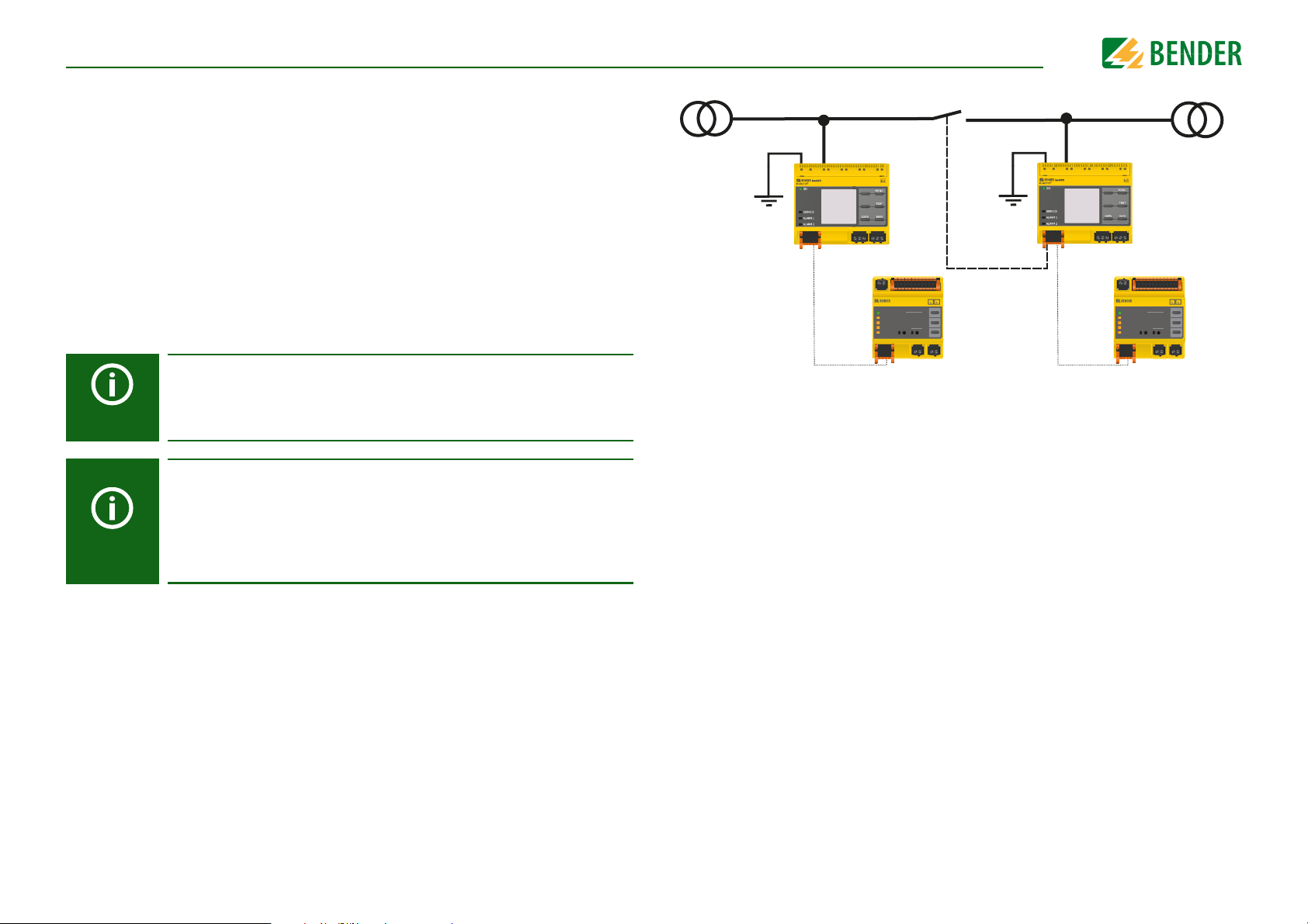
13.
IT-System 1 IT-System 2
PE
Adr.3Adr.3
Adr.1 Adr.1
PE
I LI
n
ISOSCAN®
EDS440
7
6
5
3
4
2
0
1
5
3
4
2
0
1
9
TEST
MUTE
RESET
ALARM
ALARM
ON
COM
SERVICE
CHANNELS
SLAVE ADDRESS
12
11109
87
1 2 3456
I
∆
L
I
∆
n
I LI
n
ISOSCAN®
EDS440
7
6
5
3
4
2
0
1
5
3
4
2
0
1
9
TEST
MUTE
RESET
ALARM
ALARM
ON
COM
SERVICE
CHANNELS
SLAVE ADDRESS
12
11109
87
1 2 3456
I
∆
L
I
∆
n
Special functions for coupled IT systems
13.1 Particularities when monitoring coupled IT systems
When using ISOMETER®s in IT systems, make sure that only one active ISOMETER® is connected in each interconnected system. If several ISOMETER®s are to be connected to the
IT system, ensure that only one ISOMETER® is active in the IT system via system isolation
using the digital input or Ethernet (ISOnet function).
If IT systems are interconnected via coupling switches, make sure that ISOMETER®s not
currently used are disconnected from the IT system and deactivated.
IT systems coupled via diodes or capacitances may also influence the insulation monitoring process so that a central control of the different ISOMETER®s is required.
13.2 System isolation via digital input with two coupled systems
Special functions for coupled IT systems
In order to deactivate the ISOMETER® via one of the digital inputs, the coupling switch must have a free contact.
If IT systems are interconnected via coupling switches, one ISOMETER® always remains inactive. Insulation fault location in the IT system of the inactive ISOMETER® is only possible when the associated EDS are in auto
mode (see “Setting EDS mode” on page 33). In addition, insulation fault
location with a portable EDS must be activated for the active ISOMETER®
(setting: Use portable EDS = on, see “Using a portable EDS” on page 52).
70
Via the X1 connector, the ISOMETER® can be isolated from the IT system and the measuring functions can be deactivated. Therefore, the function of the digital input in use has to
be set to "Device inactive".
If the digital input used for this function is selected, the connectors L1/+, L2, L3/- are deactivated via internal system isolating switches, the measuring function stops and the following message appears on the display: "Device inactive. Device separated".
Stored fault messages are reset when the cause of the fault has been eliminated (Reset
function).
If the digital input is no longer selected, first the connection to the IT system is restored
and afterwards, an entirely new measuring cycle for the insulation monitoring starts.
This function can be used to disconnect the second ISOMETER® selectively in coupled IT
systems via the auxiliary contact of the coupling switch.
iso685-D-P_D00170_00_M_XXDE/06.2016
Page 71

13.3 System isolation via ISOnet
CAUTION
IT-System 1 IT-System 2
PE
PE
Adr.3
Adr.1
BCOM
Adr.1
BCOM
Adr.2
BS-BusBS-Bus
Adr.1
Adr.3
I LI
n
ISOSCAN®
EDS440
7
6
5
3
4
2
0
1
5
3
4
2
0
1
9
TEST
MUTE
RESET
ALARM
ALARM
ON
COM
SERVICE
CHANNELS
SLAVE ADDRESS
12
11109
87
1 2 3456
I
∆
L
I
∆
n
I LI
n
ISOSCAN®
EDS440
7
6
5
3
4
2
0
1
5
3
4
2
0
1
9
TEST
MUTE
RESET
ALARM
ALARM
ON
COM
SERVICE
CHANNELS
SLAVE ADDRESS
12
11109
87
1 2 3456
I
∆
L
I
∆
n
The ISOnet function ensures via an Ethernet connection that only one ISOMETER® of the
interconnection is active when several ISOMETER®s are connected to an IT system.
For several ISOMETER®s to be able to measure in the same ISOnet interconnection, the settings for the BCOM system name and the BCOM subsystem have to be the same. Only the device address has to be different. If
this is not taken into account, the ISOnet function will not work.
If the ISOnet function is deactivated in an ISOMETER® in an ISOnet interconnection, it will measure continuously and will not forward measuring
commands to the next device in the interconnection.
In comparison to a solution with coupling switches and function input,
the response time will be extended because the measurement in the IT system is not carried out continuously.
The addresses of the ISOMETER®s in the ISOnet interconnection can be selected at will. The addresses do not have to be subsequent but they have
to differ from each other.
Special functions for coupled IT systemsSpecial functions for coupled IT systems
Maximum number of devices in an ISOnet interconnection: 20 devices
If in addition to the ISOnet interconnection the digital inputs are wired
and a device is deactivated via a digital input, the device will forward the
measuring authorisation until the signal at the digital input disappears.
71
Afterwards, it participates again in the measuring interconnection.
The IP address of the standard gateway must suit the subnet mask, so that
the ISOnet function can operate correctly.
iso685-D-P_D00170_00_M_XXDE/06.2016
Page 72

For the ISOnet function, the following settings are made in the menu: Alarm settings ->
IT-System 1 IT-System 2
IT-System 3IT-System 4
PE
PE
PE
PE
Ethernet
SWITCH
BCOM
Adr.1
BCOM
Adr.2
BCOM
Adr.3
BCOM
Adr.4
BS-Bus
Adr.1
Adr.3
BS-Bus
Adr.1
Adr.3
BS-Bus
Adr.1
Adr.3
BS-Bus
Adr.1
Adr.3
I LI
n
ISOSCAN®
EDS440
7
6
5
3
4
2
0
1
5
3
4
2
0
1
9
TEST
MUTE
RESET
ALARM
ALARM
ON
COM
SERVICE
CHANNELS
SLAVE ADDRESS
12
11109
87
1 2 3456
I
∆
L
I
∆
n
I LI
n
ISOSCAN®
EDS440
7
6
5
3
4
2
0
1
5
3
4
2
0
1
9
TEST
MUTE
RESET
ALARM
ALARM
ON
COM
SERVICE
CHANNELS
SLAVE ADDRESS
12
11109
87
1 2 3456
I
∆
L
I
∆
n
I LI
n
ISOSCAN®
EDS440
7
6
5
3
4
2
0
1
5
3
4
2
0
1
9
TEST
MUTE
RESET
ALARM
ALARM
ON
COM
SERVICE
CHANNELS
SLAVE ADDRESS
12
11109
87
1 2 3456
I
∆
L
I
∆
n
I LI
n
ISOSCAN®
EDS440
7
6
5
3
4
2
0
1
5
3
4
2
0
1
9
TEST
MUTE
RESET
ALARM
ALARM
ON
COM
SERVICE
CHANNELS
SLAVE ADDRESS
12
11109
87
1 2 3456
I
∆
L
I
∆
n
ISONet -> ISONet = BCOM. The ISOnet function of all ISOMETER®s existing in the system
has to be activated and the number of devices has to be determined.
Also the parameters of the Ethernet (DHCP on or IP address, subnet mask and default
gateway) and BCOM have to be set so that the devices in the ISOnet interconnection can
communicate with each other.
After starting the system, the devices initialise. The initialisation phase ends when the
configured number of devices has been reached. Then, the device starts with a measuring cycle at the lowest address. When an ISOMETER® has finished one measuring cycle,
the authorisation for insulation measurement is forwarded to the ISOMETER® with the
next higher address. While one ISOMETER® is measuring, all other ISOMETER®s are separated from the system via internal system isolation switches. By limiting to one subsystem
it is possible to have several ISOnet interconnections running in one system.
If a single device fails, the remaining ISOMETER®s continue the ISOnet operation. For the
failure of one device, two scenarios are possible:
• A device fails during the measuring procedure.
After timeout, another device takes over the measuring function.
In this way, all devices monitor each other.
• The device fails in the inactive mode.
When forwarding the measuring authorisation, the device is skipped and the next
device carries out the measurement.
If a device that has failed before returns, it is taken into the interconnection again and will
have its turn during the next run.
Special functions for coupled IT systemsSpecial functions for coupled IT systems
72
iso685-D-P_D00170_00_M_XXDE/06.2016
Page 73

14. Device profiles
Adjustment to different applications can be carried out very easily by selecting a device profile.
Nominal system
voltage
Power circuits
Control circuits
Generator AC 0…690 V 50…60 Hz
High capacitance
Inverter > 10 Hz
Inverter < 10 Hz
AC 0…690 V/
DC 0…1000 V
AC 0…230 V/
DC 0…230 V
AC 0…690 V/
DC 0…1000 V
AC 0…690 V/
DC 0…1000 V
AC 0…690 V/
DC 0…1000 V
Mains
frequency
15…460 Hz
15…460 Hz
15…460 Hz
10…460 Hz
1…460 Hz
System
leakage
capacitance
0…150 µF
0…150
0…5
0…1000
0…20
0…20
µF
µF
µF
µF
µF
Measuring
voltage
±50 V
±10 V
±50 V
±50 V
±50 V
±50 V
Description
Main circuits without dynamic frequency changes.
The universal profile is suitable for all systems primarily with constant mains frequencies and extraneous DC voltages. When using inverters and dynamic frequency control, select Inverter > 10 Hz or Inverter < 10 Hz.
This profile is used to reduce the measurement voltage to ±10 V in control systems with lower nominal voltages in order to reduce the impact by the ISOMETER® on sensitive switching elements.
This profile allows the realisation of a very fast measuring time, e.g. as required
for generator monitoring. Furthermore, this profile can be used to support fast
fault location in an IT system. The generator profile is suitable for AC systems
containing DC components.
For systems with high leakage capacitances, e.g. ship applications, the impact of
leakage capacitances on the measuring result can be significantly reduced by
selecting this profile.
This profile is used for systems with dynamic frequency control by inverters in
the range 10 to 460 Hz in order to optimise the measurement with respect to
the measuring time and quality.
For systems involving extremely low-frequency control in the range of up to
1...460 Hz and very low and continuously changing extraneous DC voltages due
to dynamic load conditions in an IT system, continuous insulation monitoring
can be optimised using this profile.
Response times see “Diagrams” on page 74.
73
iso685-D-P_D00170_00_M_XXDE/06.2016
Page 74

15. Diagrams
Ce ≤ 150 µF
C
e
≤ 50 µF
C
e
≤ 20 µF
C
e
≤ 5 µF
C
e
≤ 1 µF
Response time as a function of the response value (Ran) and system leakage
capacitance (C
e
) according to IEC 61557-8 (Un = AC 690 V, fn = 50 Hz)
1
10
100
100001000100101
Response time [sec]
Response value R
an
[kΩ]
Ce ≤ 150 µF
C
e
≤ 50 µF
C
e
≤ 20 µF
C
e
≤ 5 µF
C
e
≤ 1 µF
Response time as a function of the response value (Ran) and system leakage
capacitance (C
e
) according to IEC 61557-8 (Un = AC 230 V, fn = 50 Hz)
1
10
100
100001000100101
Response time [sec]
Response value R
an
[kΩ]
15.1 Response time profile power circuits
15.2 Response time profile control circuits
74
iso685-D-P_D00170_00_M_XXDE/06.2016
Page 75
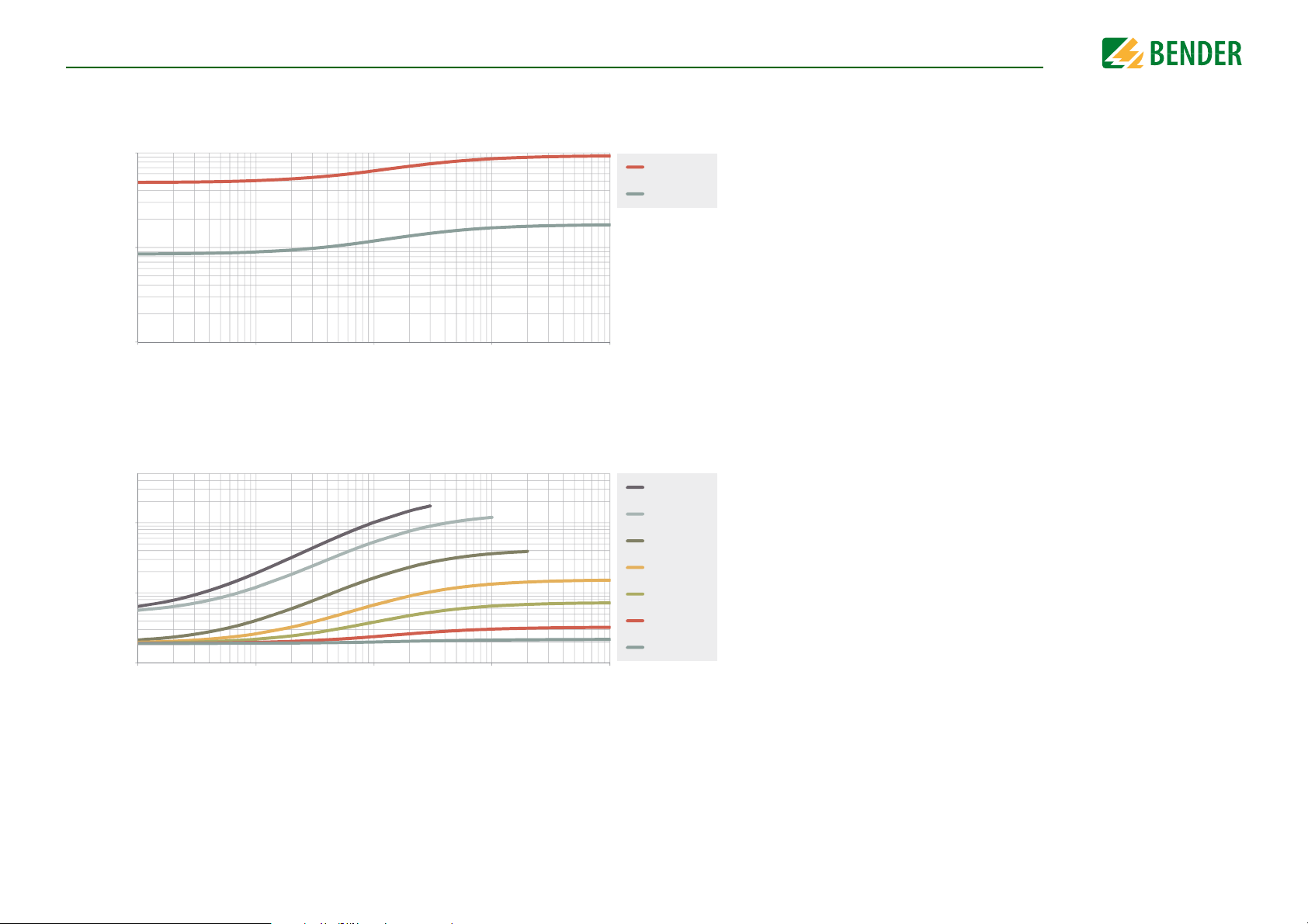
Diagrams
Ce ≤ 5 µF
C
e
≤ 1 µF
Response time as a function of the response value (Ran) and system leakage
capacitance (C
e
) according to IEC 61557-8 (Un = AC 690 V, fn = 50 Hz)
0,1
1
10
100001000100101
Response time [sec]
Response value R
an
[kΩ]
Ce ≤ 1000 µF
C
e
≤ 500 µF
C
e
≤ 150 µF
C
e
≤ 50 µF
C
e
≤ 20 µF
Ce ≤ 5 µF
Ce ≤ 1 µF
Response time as a function of the response value (Ran) and system leakage
capacitance (C
e
) according to IEC 61557-8 (Un = AC 690 V, fn = 50 Hz)
10
100
1000
100001000100101
Response time [sec]
Response value R
an
[kΩ]
15.3 Response time profile generator
15.4 Response time profile high capacitance
75
iso685-D-P_D00170_00_M_XXDE/06.2016
Page 76
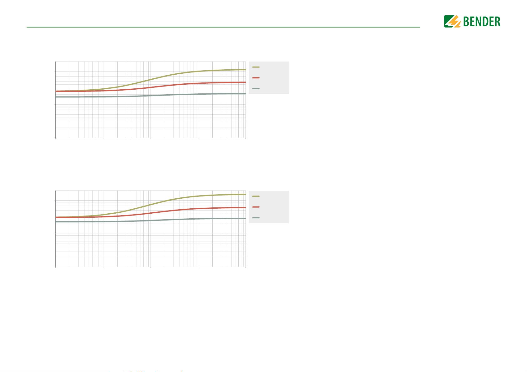
Diagrams
Ce ≤ 20 µF
C
e
≤ 5 µF
C
e
≤ 1 µF
Response time as a function of the response value (Ran) and system leakage
capacitance (C
e
) according to IEC 61557-8 (Un = AC 690 V, fn = 50 Hz)
1
10
100
100001000100101
Response time [sec]
Response value R
an
[kΩ]
Response time as a function of the response value (Ran) and system leakage
capacitance (C
e
) according to IEC 61557-8 (Un = AC 690 V, fn = 50 Hz)
1
10
100
100001000100101
Response time [sec]
Response value R
an
[kΩ]
Ce ≤ 20 µF
C
e
≤ 5 µF
C
e
≤ 1 µF
15.5 Response time profile inverter > 10 Hz
15.6 Response time profile inverter < 10 Hz
76
iso685-D-P_D00170_00_M_XXDE/06.2016
Page 77
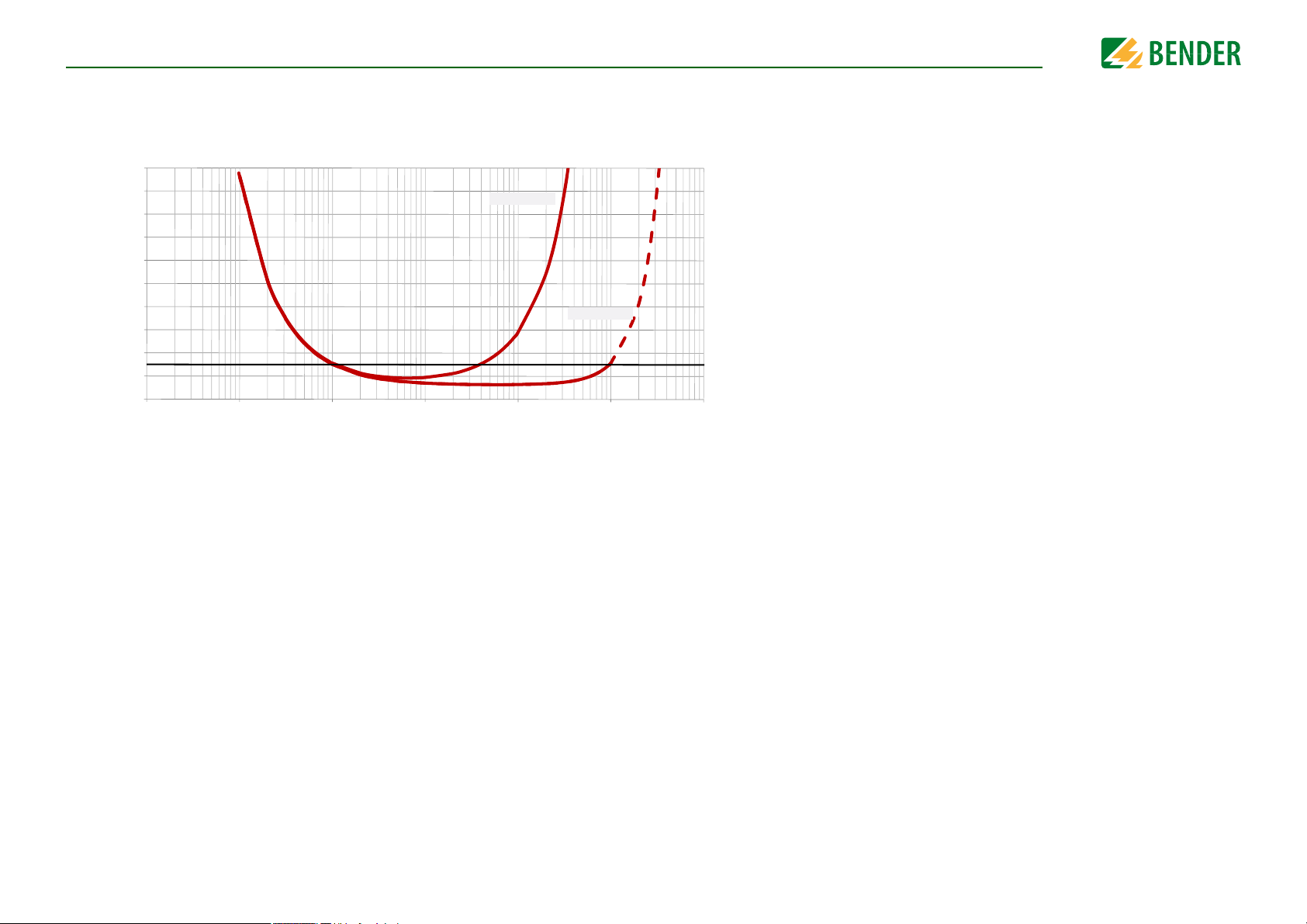
Diagrams
0%
10%
20%
30%
40%
50%
60%
70%
80%
90%
100%
0000010000100010111,0
100
(U
n
=AC 690V, f
n
=60Hz)
Operating uncertainty [%]
Ce ≤ 1000 µF
Ce ≤ 1 µF
15.7 Relative uncertainty
77
iso685-D-P_D00170_00_M_XXDE/06.2016
Page 78

16. Alarm messages
16.1 Alarm messages of the ISOMETER®
Alarm message Description Measures Reference LED indicators
Insulation fault
Insulation fault
Check L1-L2-L3 for correct connection!
Check E-KE connections
for interruptions!
Service mode active! The device is in maintenance condition • Contact Bender Service SERVICE lights up
The profile does not suit
the application!
No DHCP server found! Connection problem at the Ethernet interface
Check time and date! Time and date have not been set yet
An insulation fault exists. The insulation resistance falls
below the response value R
An insulation fault exists. The insulation resistance falls
below the response value R
No low-resistance connection between the line conductors
No low-resistance connection between terminals E and
KE to earth (PE)
Wrong profile selected for this application
an1
an2
.
.
• Observe insulation resistance in the monitored system and, if necessary, eliminate fault.
• Reset fault message by pressing the reset button
• If necessary, locate insulation fault using the EDS
• Eliminate insulation fault in the system being monitored
• Reset fault message by pressing the reset button
• Check the wiring of terminals L1/+, L2 and L3/- to the IT system
• Press the test button
• Check mains voltage
•Check fuses
• Check set system type
• Check the wiring of terminals E and KE to earth (PE)
• Press the test button
• Check measured system capacitance or mains frequency in the
Info menu
• Select another profile taking into consideration the characteristics
• Check cable connection at the Ethernet interface
• Check the DHCP server's availability
• Check the DHCP's interface configuration in the device
• Set local time and date
(in case of voltage failure a buffer for three days)
“Function description” on page 12
“Function description” on page 12
“Connection” on
page 20
& menu setting
“System type” on
page 45
“Connection” on
page 20
“Device profiles” on
page 73 &
“Profile” on page 45
“DHCP” on page 61
“Clock” on page 60
ALARM 1 lights
ALARM 2 lights
ALARM 1 + ALARM
2 flash alternately
ALARM 1 + ALARM
2 flash in common
mode
Load on X1 too high! Sum of the external loads on X1 is too high
Device error x.xx Internal device fault
The configured number of devices does not match the
Num.ISOnet devices
number of devices that are actually included in the
ISOnet interconnection.
78
• Check load at X1.+, X1.Q1 and X1.Q2
• Check ambient temperature
• Press the TEST button
• Switch the supply voltage off and on
•Contact Bender Service
•Check settings
• Check Ethernet connection
SERVICE lights up
“System isolation via
ISOnet” on page 71
iso685-D-P_D00170_00_M_XXDE/06.2016
Page 79

Alarm messages
Alarm message Description Measures Reference LED indicators
Failure address
Disturbance ISOnet
Start search for EDS
channels now?
Malfunction overcurrent
Overtemperature PGH
DC offset voltage There is a DC offset voltage in the system. • Check insulation fault and eliminate fault of DC components.
One device of the
ISOnet interconnection is not accessible
General fault at ISOnet, which is not covered by
"Num.ISOnet devices" and "Failure address". For example, sending messages can fail or another device cannot process a message.
A device on the BS bus has failed or cannot be
detected. The ISOMETER® searches automatically for
channels.
The locating current for the insulation fault location is
higher than the set limit value. The insulation fault location is aborted and the insulation resistance measurement is continued even if an insulation fault is still
active. The insulation fault location is only restarted
when the alarm message has been reset and there still
exists an insulation fault.
The locating current injector in the ISOMETER® has
heated up. The ISOMETER® stops the locating current
injector until it cools down and then restarts it.
• Check Ethernet connection
• Check device function
• Check Ethernet connection
• Check device function
• Test wiring of terminals A, B to X1 of all devices
• Start search for EDS channels now
• Reset fault message by pressing the RESET button
• If the fault does not disappear after pressing the RESET button, the
device is defective. In this case, contact Bender Service.
• If necessary, reduce the maximum locating current
• Contact Bender Service if the fault does not disappear or occurs
more frequently
“System isolation via
ISOnet” on page 71
“System isolation via
ISOnet” on page 71
“BS bus” on page 68
and “Scanning
channels” on
page 52
“Current” on page 51
“Setting EDS current” on page 34
“DC alarm” on
page 44
Undervoltage Operating outside the specified supply voltage range • Check supply voltage
Overvoltage Operating outside the specified supply voltage range • Check supply voltage
79
iso685-D-P_D00170_00_M_XXDE/06.2016
Page 80

Alarm messages
16.2 Alarm messages of the EDS
Alarm message Description Measures Reference LED indicators
Interferences during insulation fault location
Insulation fault location
disturbed!
insulation fault x mA
Possible causes:
• Low-frequency residual currents
• External magnetic fields
If an insulation fault is located, the message Insulation
fault 5 mA appears on the display. The level of the locat-
ing current gives information regarding the faulty out-
going circuit. The higher the locating current, the lower
the insulation resistance on the detected channel.
• Identify interference sources and eliminate them
• Determine cause of the insulation fault and eliminate it.
Interference CT connection
CT short circuit
Residual current
A measuring current transformer has not been con-
nected correctly or does not work.
Connection fault of CTs
Possible causes:
• Measuring current transformer defective
• Power supply cable short-circuited
The set response value of the residual current has been
exceeded on one channel.
Additionally, read the operating manual of the EDS.
• Check wiring of the measuring current transformers
• Check device function
• Start new search for EDS channels
• Deactivate channel without CT
• Replace defective measuring current transformer
• Check cables
• Determine cause of the exceeded residual current and eliminate
fault.
“Scanning channels”
on page 52 &
“Activating channels” on page 53
80
iso685-D-P_D00170_00_M_XXDE/06.2016
Page 81

17. Technical data
Technical data
17.1 Tabular data
Insulation coordination according to IEC 60664-1/IEC 60664-3
Definitions:
Measuring circuit (IC1)............................................................................................................................................. (L1/+, L2, L3/-)
Supply circuit (IC2)................................................................................................................................................................... A1, A2
Output circuit 1 (IC3)...........................................................................................................................................................11, 12, 14
Output circuit 2 (IC4)...........................................................................................................................................................21, 22, 24
Control circuit (IC5) .................................................................................................................................... (E, KE), (X1, ETH, X3, X4)
Rated voltage....................................................................................................................................................................................1000 V
Overvoltage category (OVC)..................................................................................................................................................................... III
Rated impulse voltage:
IC1 / (IC2-5) ................................................................................................................................................................................. 8 kV
IC2 / (IC3-5) ................................................................................................................................................................................. 4 kV
IC3 / (IC4-5) ................................................................................................................................................................................. 4 kV
IC4 / IC5 ........................................................................................................................................................................................ 4 kV
Rated insulation voltage:
IC1 / (IC2-5) .............................................................................................................................................................................1000 V
IC2 / (IC3-5) ...............................................................................................................................................................................250 V
IC3 / (IC4-5) ...............................................................................................................................................................................250 V
IC4 / IC5 ......................................................................................................................................................................................250 V
Pollution degree for accessible parts on the outside of the device housing (U
Pollution degree for accessible parts on the outside of the device housing (U
Protective separation (reinforced insulation) between:
IC1 / (IC2-5) ................................................................................................................................................................OVC III, 1000 V
IC2 / (IC3-5) .................................................................................................................................................................. OVC III, 300 V
IC3 / (IC4-5) .................................................................................................................................................................. OVC III, 300 V
IC4 / IC5 .........................................................................................................................................................................OVC III, 300 V
Voltage test (routine test) according to IEC 61010-1:
IC2 / (IC3-5) ........................................................................................................................................................................ AC 2,2 kV
IC3 / (IC4-5) ........................................................................................................................................................................ AC 2,2 kV
IC4 / IC5 ............................................................................................................................................................................... AC 2,2 kV
Supply voltage
Supply voltage range U
Tolerance of U
Maximum permissible input current of U
Frequency range of U
...............................................................................................................................................AC/DC 24…240 V
s
..................................................................................................................................................................... -20…+15 %
s
................................................................................................................................................. DC, 50…400 Hz
s
.................................................................................................................................... 650 mA
s
Tolerance of the frequency range of Us................................................................................................................................. -5…+15 %
Power consumption, typically 50 Hz (400 Hz)..................................................................................... ≤ 12 W/21 VA (≤ 12 W/45 VA)
< 690 V)..................................................................... 3
n
>690 < 1000 V)........................................................ 2
n
IT system being monitored
Nominal system voltage range U
..................................................................................................................................... AC 0…690 V
n
............................................................................................................................................................................................. DC 0…1000 V
Tolerance of U
Frequency range of U
Max. AC voltage U
..................................................................................................................................................................... AC/DC +15 %
n
....................................................................................................................................................... DC, 1…460 Hz
n
in the frequency range fn = 1…10 Hz ............................................................................ U
~
= 110 V/Hz * f
~ max
n
Response values
Response value R
Response value R
(alarm 1) ...........................................................................................................................................1 kΩ…10 MΩ
an1
(alarm 2) ...........................................................................................................................................1 kΩ…10 MΩ
an2
Relative uncertainty (acc. to IEC 61557-8) ............................................................................profile dependent, ±15 %, at least ±1 kΩ
Hysteresis ...................................................................................................................................................................... 25 %, at least 1 kΩ
Time response
Response time t
at RF = 0.5 x Ran (Ran = 10 kΩ) and Ce = 1 μF according to IEC 61557-8.................................................................
an
................................................................................................................................................. profile dependent, typ. 4 s (see diagrams)
Start-up delay T
............................................................................................................................................................... 0…120 s
start-up
Measuring circuit
Measuring voltage U
Measuring current I
Internal resistance R
Permissible extraneous DC voltage U
Permissible system leakage capacitance C
.....................................................................................profile dependent, ±10 V, ±50 V (see profile overview)
m
...................................................................................................................................................................≤ 403 μA
m
,Zi............................................................................................................................................................... ≥ 124 kΩ
i
....................................................................................................................................... ≤ 1200 V
fg
........................................................................................... profile dependent, 0…1000 μF
e
Measuring circuit for insulation fault location (EDS):
Locating current I
........................................................................................................................................... 1/1.8/2.5/5/10/25/50 mA
L
Measuring ranges
Measuring range f
Tolerance measurement of f
Voltage range measurement of f
Measuring range U
................................................................................................................................................................ 10…460 Hz
n
............................................................................................................................................. ±1 % ±0.1 Hz
n
......................................................................................................................................AC 25…690 V
...........................................................................................................................................................AC 25…690 V
n
n
...........................................................................................................................................................................................DC 25…1000 V
Voltage range measurement of U
Tolerance measurement of U
Measuring range C
................................................................................................................................................................0…1000 μF
e
Tolerance measurement of C
Frequency range measurement of C
1)
Min. insulation resistance measurement of C
..................................................................................................................................... AC/DC > 10 V
n
.................................................................................................................................................±5 % ±5 V
n
........................................................................................................................................... ±10 % ±10 μF
e
.............................................................................................................................. DC, 30…460 Hz
e
..........................................depending on the profile and coupling mode, typ. > 10 kΩ
e
81
iso685-D-P_D00170_00_M_XXDE/06.2016
Page 82

Technical dataTechnical data
Display
Indication ....................................................................................................................... graphic display 127 x 127 pixels, 40 x 40 mm
Display range measured value .........................................................................................................................................0.1 kΩ…20 MΩ
LEDs
ON (operation LED) ............................................................................................................................................................................ green
SERVICE............................................................................................................................................................................................. yellow
ALARM 1 ........................................................................................................................................................................................... yellow
ALARM 2 ........................................................................................................................................................................................... yellow
Digital inputs
Number ...................................................................................................................................................................................................... 3
Operating mode, adjustable................................................................................................................................... active high, active low
Functions ............................................................ off, test, reset, deactivate device, start initial measurement, insulation fault location
Voltage...........................................................................................................................................Low DC -3…5 V, High DC 11…32 V
Cable length X1 ............................................................................................................................................................................... ≤ 1 m
Digital outputs
Number ...................................................................................................................................................................................................... 2
Operating mode, adjustable.................................................................................................................................................active, passive
Functions .....................................................................................................................................................................................................
off, Ins. alarm 1, Ins. alarm 2, connection fault, DC- alarm, DC+ alarm, symmetrical alarm,
...................................... device fault, common alarm, measurement complete, device inactive, DC offset alarm, common alarm EDS
Voltage............................................................................................................................. passive DC 0…32 V, active DC 0/19.2…32 V
Max. current internal sum X1................................................................................................................................................ max. 200 mA
Max. current external per channel................................................................................................................................................max. 1 A
Cable length X1 ................................................................................................................................................................................ ≤ 1 m
Analogue output
Number ...................................................................................................................................................................................................... 1
Operating mode................................................................................................................................ linear, midscale point 28 kΩ/120 kΩ
Functions ...........................................................................................................................................................insulation value, DC offset
Current, voltage 0...20 mA (< 600 Ω), 4…20 mA (< 600 Ω), 0…400 μA (< 4 kΩ), 0…10 V (> 1 kΩ), 2…10 V (> 1 kΩ)
Tolerance .........................................................................................................................................................................................±20 %
Interfaces
Field bus:
Interface/protocol.................................................................................................................................... web server/Modbus TCP/BCOM
Data rate........................................................................................................................................................... 10/100 Mbit/s, autodetect
Max. amount Modbus requests .................................................................................................................................................... < 100/s
Cable length ................................................................................................................................................................................. ≤ 100 m
Connection........................................................................................................................................................................................... RJ45
2)
IP address .........................................................................................................................................................DHCP/manual 192.168.0.5
Network mask..................................................................................................................................................................... 255.255.255.0
BCOM address ........................................................................................................................................................................... system-1-0
Function ..............................................................................................................................................................communication interface
ISOnet:
Number ISOnet devices ...................................................................................................................................................................... ≤ 20
Sensor bus:
Interface/protocol ...................................................................................................................................................................... RS-485/BS
....................................................... 9.6 kBaud/s
Data rate.........................................................................................................................
...
Cable length ...............................................................................................................................................................................≤ 1200 m
Cable: twisted pair, one end of shield connected to PE................................................................... recommended: J-Y(St)Y min. 2x0.8
Connection ................................................................................................................................................................. terminals X1.A, X1.B
Terminating resistor at the beginning and at the end of the transmission path..............................120 Ω, can be connected internally
Device address, BS bus .................................................................................................................................................................... 1…90
Switching elements
Number of switching elements.............................................................................................................................. 2 changeover contacts
Operating mode.......................................................................................................................................... N/C operation/N/O operation
Contact 11-12-14 .......................................................................................................................................................................................
off, Ins. alarm 1, Ins. alarm 2, connection fault, DC- alarm, DC+ alarm, symmetrical alarm,
...................................... device fault, common alarm, measurement complete, device inactive, DC offset alarm, common alarm EDS
Contact 21-22-24 .......................................................................................................................................................................................
off, Ins. alarm 1, Ins. alarm 2, connection fault, DC- alarm, DC+ alarm, symmetrical alarm,
...................................... device fault, common alarm, measurement complete, device inactive, DC offset alarm, common alarm EDS
Electrical endurance under rated operating conditions, number of cycles.................................................................................... 10.000
Contact data acc. to IEC 60947-5-1:
Utilisation category................................................................................................................... AC-13 / AC-14 / DC-12 / DC-12 / DC-12
Rated operational voltage .............................................................................................................. 230 V / 230 V / 24 V / 110 V / 220 V
Rated operational current ........................................................................................................................... 5 A / 3 A / 1 A / 0.2 A / 0.1 A
Rated insulation voltage ≤ 2000 m NN ........................................................................................................................................... 250 V
Rated insulation voltage ≤ 3000 m NN ........................................................................................................................................... 160 V
Minimum contact rating ...................................................................................................................................... 1 mA at AC/DC ≥ 10 V
Environment/EMC
EMC ................................................................................................................................................................................. IEC 61326-2-4
3)
Ambient temperatures:
Operating temperature........................................................................................................................................................-25…+55 °C
Transport ..............................................................................................................................................................................-40…+70 °C
Long-term storage...............................................................................................................................................................-40…+70 °C
Classification of climatic conditions acc. to IEC 60721:
Stationary use (IEC 60721-3-3) ....................................................................................3K5 (except condensation and formation of ice)
82
iso685-D-P_D00170_00_M_XXDE/06.2016
Page 83
Technical dataTechnical data
Transport (IEC 60721-3-2) ...................................................................................................................................... ............................ 2K3
Long-term storage (IEC 60721-3-1) ................................................................................................................................... ................ 1K4
Classification of mechanical conditions acc. to IEC 60721:
Stationary use (IEC 60721-3-3)...........................................................................................................................................................3M4
Transport (IEC 60721-3-2)...................................................................................................................................................................2M2
Long-term storage (IEC 60721-3-1) ...................................................................................................................................................1M3
Area of application ............................................................................................................................................................... ≤ 3000 m NN
Connection
Connection type................................................................................................... pluggable screw-type terminal or push-wire terminal
Screw-type terminals:
Nominal current............................................................................................................................................................................... ≤ 10 A
Tightening torque.......................................................................................................................................... 0.5…0.6 Nm (5…7 lb-in)
Conductor sizes.........................................................................................................................................................................AWG 24-12
Stripping length................................................................................................................................................................................. 7 mm
rigid/flexible ....................................................................................................................................................................... 0.2…2.5 mm²
flexible with ferrules, with/without plastic sleeve..........................................................................................................0.25…2.5 mm²
Multiple conductor, rigid....................................................................................................................................................... 0.2…1 mm²
Multiple conductor, flexible ............................................................................................................................................... 0.2…1.5 mm²
Multiple conductor, flexible with ferrule without plastic sleeve .......................................................................................0.25…1 mm²
Multiple conductor, flexible with TWIN ferrule with plastic sleeve..................................................................................0.5…1.5 mm²
Push-wire terminals:
Nominal current............................................................................................................................................................................... ≤ 10 A
Conductor sizes.........................................................................................................................................................................AWG 24-12
Stripping length............................................................................................................................................................................... 10 mm
rigid/flexible ....................................................................................................................................................................... 0.2…2.5 mm²
flexible with ferrules, with/without plastic sleeve..........................................................................................................0.25…2.5 mm²
Multiple conductor, flexible with TWIN ferrule with plastic sleeve..................................................................................0.5…1.5 mm²
Push-wire terminals X1:
Nominal current................................................................................................................................................................................. ≤ 8 A
Conductor sizes.........................................................................................................................................................................AWG 24-16
Stripping length............................................................................................................................................................................... 10 mm
rigid/flexible ....................................................................................................................................................................... 0.2…1.5 mm²
flexible with ferrule without plastic sleeve...................................................................................................................... 0.25…1.5 mm²
flexible with TWIN ferrule with plastic sleeve .................................................................................
..............................0.25…0.75 mm²
DIN rail mounting acc. to............................................................................................................................................................ IEC 60715
Screw fixing...................................................................................................................................................... 3 x M4 with mounting clip
Enclosure material ............................................................................................................................................................... polycarbonate
Flammability class .................................................................................................................................................................................V-0
ANSI code ............................................................................................................................................................................................... 64
Dimensions (W x H x D)............................................................................................................................................... 108 x 93 x 110 mm
Weight ........................................................................................................................................................................................... < 510 g
Option "W" data different from the standard version
Ambient temperatures:
Operating temperature........................................................................................................................................................-40…+70 °C
Transport ..............................................................................................................................................................................-40…+85 °C
Long-term storage...............................................................................................................................................................-40…+70 °C
Classification of climatic conditions acc. to IEC 60721:
Stationary use (IEC 60721-3-3) ................................................................................. 3K5 (condensation and formation of ice possible)
Classification of mechanical conditions acc. to IEC 60721:
Stationary use (IEC 60721-3-3) ........................................................................................................................................................ 3M7
1)
at a frequency > 200 Hz, the connection of X1 must be insulated. Only permanently installed devices which at least have over-
voltage category CAT2 (300V) may be connected.
2)
Indication limited outside the temperature range -25…+55 °C.
3)
This is a class A product. In a domestic environment, this product may cause radio interference. In this case, the user may be re-
quired to take corrective actions.
17.2 Option W
Devices with the suffix "W“ feature increased shock and vibration resistance.
The electronics is covered with a special varnish to provide increased protection against
mechanical stress and moisture.
Combination of ISOMETER® sensor variant with FP200:
The requirements of Option "W" will only be fulfilled when the ISOMETER®
sensor variant is mounted on DIN rail and connected to the FP200 via the
patch cable.
Refer also to the quick-start guide FP200 (Document number D00169).
h
er
Ot
Operating mode........................................................................................................................................................ continuous operation
Mounting display oriented, cooling slots must be ventilated vertically
Degree of protection internal components ......................................................................................................................................... IP40
Degree of protection terminals ........................................................................................................................................................... IP20
83
iso685-D-P_D00170_00_M_XXDE/06.2016
Page 84
Technical dataTechnical data
17.3 Standards and certifications
The ISOMETER® has been developed in compliance with the following standards:
• DIN EN 61557-8 (VDE 0413-8)
• IEC 61557-8
• DIN EN 61557-9 (VDE 0413-9)
• IEC 61557-9
17.4 Ordering details
Type
iso685-D-P
iso685W-D-P*
Combination
iso685-S-P + FP200
Supply voltage U
AC 24…240 V; 50…400 Hz
DC 24…240 V
AC 24…240 V; 50…400 Hz
DC 24…240 V
AC 24…240 V; 50…400 Hz
DC 24…240 V
S
Art. No.
B91067030
B91067030W
B91067230
Insulation fault locators
Typ e
EDS440-S-1 AC/DC 24…240V 2…10mA B 9108 0201
EDS440W-S-1 AC/DC 24…240V 2…10mA B 9108 0201W
EDS440-L-4 AC/DC 24…240V 2…10mA B 9108 0202
EDS440W-L-4 AC/DC 24…240V 2…10mA B 9108 0202W
EDS441-S-1 AC/DC 24…240V 0,2…1mA B 9108 0204
EDS441W-S-1 AC/DC 24…240V 0,2…1mA B 9108 0204W
EDS441-L-4 AC/DC 24…240V 0,2…1mA B 9108 0205
EDS441W-L-4 AC/DC 24…240V 0,2…1mA B 9108 0205W
EDS441-LAB-4 AC/DC 24…240V 0,2…1mA B 9108 0207
EDS441W-LAB-4 AC/DC 24…240V 0,2…1mA B 9108 0207W
Supply voltage U
*
Response value Art. no.
S
Combination
iso685W-S-P + FP200W*
AC 24…240 V; 50…400 Hz
DC 24…240 V
B91067230W
* Option W: Increased shock and vibration resistance 3K5, 3M7; -40…+70 °C
84
* Absolute values
iso685-D-P_D00170_00_M_XXDE/06.2016
Page 85

Accessories
Description Art. No.
Technical dataTechnical data
iso685 mechanical accessories comprising:
terminal cover and 2 mounting clips*
iso685 plug kit, screw terminals* B91067901
iso685 plug kit, with push-wire terminals B91067902
Front cover 144x72 transparent (for IP65) B 98060005
BB bus 6TE connector B98110001
B91067903
* included in the scope of delivery
Suitable system components
Description Type Art. No.
Suitable measuring instruments
SKMP**: 28 kΩ,120 kΩ
Current values: 0…400 µA, 0…20 mA
(for more information, click here)
Display for front panel mounting
7204-1421 B986763
9604-1421 B986764
9620-1421 B986841
FP200 B91067904
FP200W B91067904W
iso685-S-P
(only in combination with FP200)
iso685W-S-P*
(only in combination with FP200)
Supply voltage:
AC 24…240 V; 50…400 Hz
DC 24…240 V
Supply voltage:
AC 24…240 V; 50…400 Hz
DC 24…240 V
B91067130
B91067130W
* Option W: Increased shock and vibration resistance 3K5, 3M7; -40…+70 °C
**
SKMP = midscale point
85
iso685-D-P_D00170_00_M_XXDE/06.2016
Page 86

18. Glossary
• BB bus
• BCOM Protocol for communication between Bender devices via an IP-based network.
• BS bus The Bender sensor bus is an interface which enables Bender devices to communicate with each other (RS-485 interface).
• DHCP Dynamic Host Configuration Protocol. It is used to assign the network configuration to Clients via a server.
• EDS Insulation fault locator for fault location in an IT system.
• EDS button
•EDS mode
•ISOnet
• Modbus TCP Modbus is an international widely spread protocol for data transfer.
•PGH
• "PGH ON" LED The "PGH ON" LED flashes during insulation fault location. It indicates that the locating current for the insulation fault location is generated.
• System (BCOM)
The BB bus is an interface which enables Bender devices to communicate with each other (Bender-internal device bus).
The BB bus can be used with an ISOMETER® and one or more EDS44…-S.
The shortcut button "EDS" manually starts the insulation fault location, which runs continuously until the button is pressed again, which stops the
process immediately.
(refer also to “Display elements and device buttons” on page 18).
The insulation fault location can be carried out in three different modes. Depending on the mode, the insulation fault location starts and stops due
to different conditions (see also “Mode” on page 52).
Only one ISOMETER® may exist in an isolated system. If several networks monitored by an ISOMETER® are coupled, this function ensures via an
Ethernet connection that only one ISOMETER® is actively measuring.
PGH stands for locating current injector. The locating current injector generates a periodic locating current for insulation fault location. This locating current is detected by the measuring current transformers connected to the EDS and evaluated by the EDS.
The system is the entire installation that is visible for the customer and defined by the customer. The BCOM communication takes place within this
system. Naturally, different systems can exist independently in one network.
• Subsystem (BCOM)
• Web server A web server presents the device functions graphically. The web server can be used for reading out measured values and for parameter setting.
86
The subsystem structures parts of the system as units defined by the customer, e.g. all PQ devices. A typical subsystem are also "non BCOM-capable" devices that are hidden behind a proxy.
iso685-D-P_D00170_00_M_XXDE/06.2016
Page 87

Index
Index
A
Accessories 85
Alarm
Alarm 1 13
Alarm 2 13
Reset alarm message 59
Settings 44
B
BB bus 26, 86
BCOM 64, 86
BS bus 68, 86
Button
DATA 18
EDS 18
ESC 18
Info 18
MENU 18
OK 18
RESET 18
TEST 18
Buttons 18
C
Characteristic curves 74
Commissioning 32
Commissioning wizard 32, 33
Initial commissioning 32
Recommissioning 33
Communication interfaces 64
Compatibility 14
Connection
3(N)AC system 22
AC system 22
BB bus 26
Connection requirements 20
Connectors 17
DC system 23
Ethernet interface 24
Relay 1 interface (11 12 14) 25
Relay 2 interface (21 22 24) 25
Supply voltage 24
X1 interface 23
Control circuits 73
Coupled IT systems 70
Coupling monitoring 45
D
Date 33, 60
Setting the date 33, 60
Device buttons 18
Device profiles 33, 45
DHCP 61, 86
Diagrams 74
Dimensions 15
Display 18, 36
Data - isoGraph 38
Fault display (active) 36
Fault display (inactive) 37
Fault memory 38
History memory 39
Initial measurement 40
Insulation fault location 39
Limit values for R(an) 36
Measuring pulse 39
Signal quality of the measurement 36
Standard display 36
Display elements 18
87
iso685-D-P_D00170_00_M_XXEN/06.2016
Page 88

Index Index
E
EDS 86
Device settings 56
Inputs 56
Outputs 54
Ethernet interface 24
F
Function description
Insulation fault location 13
ISOMETER 11, 12
ISOnet 71
G
Glossary 86
H
Hazards when handling the device 10
History memory 39
I
Initial measurement 40, 59
Inputs
EDS 56
Inputs ISOMETER 46
Insulation fault location 13, 69
EDS button 18
PGH ON LED 18
Response value I∆L 54
Response value I∆n 54
Test current 51
Insulation resistance
Activate/deactivate measurement 45
Intended use 10
Interfaces 60
BB bus 26
BCOM 61, 64
BS bus 68
Ethernet 61, 64
Modbus TCP 61
Modbus/TCP 64
Web server 65
X1 23
ISOnet 71, 86
L
LEDs 18
ALARM 1 18
ALARM 2 18
ON 18
PGH ON 18, 86
SERVICE 18
M
Mains frequency 73
Mains voltage 11
Measured values 59
View measured values 59
Measuring pulse 39
Menu 41
Minimum current rectifier 21
Minimum distance 20
Modbus TCP 86
Modbus/TCP 64
Mounting
DIN rail mounting 20
Screw mounting 19
N
Nominal system voltage 73, 81
Nominal voltage 20
88
iso685-D-P_D00170_00_M_XXEN/06.2016
Page 89

Index Index
Normal operation 36
O
Operating controls 18
Operating mode 46
Operation
Commissioning 21, 32
Commissioning EDS 35
Option W 83
Ordering information 84
Outputs
EDS 54
ISOMETER 47
P
Password 62
PGH 86
Product description 12
Profiles
Description 73
Overview 73
Set profile 33, 45
Protective earth conductor (PE) 20
S
Safety instructions 8
Self test 14
Service menu 59, 62
Set language 33, 59
Set system type of the system to be monitored 33
Setting the time 33, 60
Settings 44
Basic settings 59
Signal quality of the measurement 36
Start-up delay 45
System leakage capacitance 11, 73
T
Technical data 81
Test
Manual test 59
Self test 14
W
W (W option) 83
Warranty 11
Web server 65, 86
R
Response time
Profile control circuits 74
Profile generator 75
Profile high capacitance 75
Profile inverter 10 Hz 76
Profile power circuits 74
Relative uncertainty 77
Response value 11, 81
I∆L 54
Set Ran1, Ran2 34
89
iso685-D-P_D00170_00_M_XXEN/06.2016
Page 90

Bender GmbH & Co. KG
Postbox 1161 • 35301 Gruenberg • Germany
Londorfer Straße 65 • 35305 Gruenberg • Germany
Customer service
Service hotline: 0700-BenderHelp (Telephone und Fax)
Carl-Benz-Straße 8 • 35305 Gruenberg • Germany
Tel.: +49 6401 807-0
Fax: +49 6401 807-259
E-Mail: [email protected]
Web: www.bender.de
Tel.: +49 6401 807-760
Fax: +49 6401 807-629
E-Mail: [email protected]
Web: http://www.bender.de
BENDER Group
Photos: Bender archive.
 Loading...