


Manual
EN
ISOMETER® iso1685FR
SERV
ICE
A
LARM
2
I
SOMETER
®
i
so16
85
ON
A
L
ARM 1
PGH ON
A
1
A
2
E
KE
k
l
kT
IT
A
B
S
R
S
-4
8
5
Term.
o
o
n
CA
N
1
CA
N
2
I2
+
I2-
I1+
I1-
3
1
32
3
4
K3
2
1
2
2
2
4
K
2
1
1
1
2
1
4
K
1
iso1685FRM
Insulation monitoring device
for unearthed AC systems
(IT systems) up to AC 5 kV
iso1685FR: Software version D0407 V1.1x
iso1685FRM with analogue output: Software version D0563 V1.0x
iso1685FR(M)_D00002_02_M_XXEN/06.2017

Bender GmbH & Co. KG
Postfach 1161 • 35301 Grünberg • Germany
Londorfer Straße 65 • 35305 Grünberg • Germany
Tel.: +49 6401 807-0
Fax: +49 6401 807-259
E-Mail: info@bender.de
Web: www.bender.de
Customer service
Service-Hotline: 0700-BenderHelp (Telephone and Fax)
Carl-Benz-Straße 8 • 35305 Grünberg • Germany
Tel.:+49 6401 807-760
Fax:+49 6401 807-629
E-Mail:info@bender-service.com
Fotos: Bender archive.
© Bender GmbH & Co. KG
All rights reserved.
Reprint only with permission
of the publisher.
Subject to change!

Table of contents
1. Important information ........................................................................................................................... 7
1.1 How to use this manual ................................................................................................................................................ 7
1.2 Technical support ........................................................................................................................................................... 8
1.2.1 First level support ........................................................................................................................................................... 8
1.2.2 Repair service .................................................................................................................................................................... 8
1.2.3 Field service ....................................................................................................................................................................... 8
1.3 Training courses .............................................................................................................................................................. 9
1.4 Delivery conditions ......................................................................................................................................................... 9
1.5 Storage ................................................................................................................................................................................ 9
1.6 Disposal .............................................................................................................................................................................. 9
2. Safety instructions ................................................................................................................................. 11
2.1 General safety instructions ........................................................................................................................................ 11
2.2 Work activities on electrical installations ............................................................................................................. 11
2.3 Device specific safety information .......................................................................................................................... 12
2.4 Address setting and termination ............................................................................................................................. 13
2.5 Intended use ................................................................................................................................................................... 13
3. Function ................................................................................................................................................... 15
3.1 Features ............................................................................................................................................................................ 15
3.2 Product description ...................................................................................................................................................... 15
3.2.1 General product description ..................................................................................................................................... 15
3.2.2 Particularities of the ISOMETER® iso1685FRM .................................................................................................... 15
3.3 Functional description ................................................................................................................................................ 16
3.3.1 Insulation monitoring .................................................................................................................................................. 16
3.3.1.1 Active method (SSCP) .................................................................................................................................................. 16
3.3.1.2 Passive method .............................................................................................................................................................. 17
3.3.2 Connection monitoring .............................................................................................................................................. 17
3.3.3 Assignment of the alarm relays K1, K2, K3 ........................................................................................................... 17
3.3.4 Measured value transmission ................................................................................................................................... 17
3.4 History memory ............................................................................................................................................................. 17
3.5 Self test .............................................................................................................................................................................. 18
3.5.1 Self test after connection to the supply voltage ................................................................................................ 18
3.5.2 Continuous self test during operation .................................................................................................................. 18
iso1685FR(M)_D00002_02_M_XXEN/06.2017
3

Inhaltsverzeichnis
4. Device overview ..................................................................................................................................... 19
4.1 Dimensions ...................................................................................................................................................................... 19
4.2 Connections .................................................................................................................................................................... 20
4.3 Display and operating elements ............................................................................................................................. 21
4.3.1 Operating elements ..................................................................................................................................................... 21
4.3.2 Melde-LEDs auf dem Gehäuseoberteil .................................................................................................................. 22
5. Installation, connection and commissioning ................................................................................... 23
5.1 Installation ....................................................................................................................................................................... 23
5.2 Connection ...................................................................................................................................................................... 23
5.2.1 Connection requirements .......................................................................................................................................... 23
5.2.2 Wiring diagram with Modbus RTU (ISOMETER® iso 1685FR, iso1685FRM) .............................................. 25
5.2.3 Anschlussplan mit Modbus RTU (ISOMETER® iso1685FRM) .......................................................................... 26
5.2.4 Step-by-step connection of the ISOMETER®iso1685FR ................................................................................... 27
5.2.5 Step-by-step connection of the iso1685FRM ISOMETER® .............................................................................. 28
5.3 Commissioning .............................................................................................................................................................. 28
5.3.1 Commissioning of the ISOMETER® iso1685FR .................................................................................................... 29
5.3.2 Commissioning of the ISOMETER® iso1685FRM ................................................................................................ 30
6. Device communication ......................................................................................................................... 31
6.1 Device communication via the BMS bus .............................................................................................................. 31
6.1.1 RS-485 interface with BMS protocol ....................................................................................................................... 31
6.1.2 Topology of the RS-485 network ............................................................................................................................. 32
6.1.3 BMS protocol .................................................................................................................................................................. 32
6.1.4 Commissioning of an RS-485 network with BMS protocol ............................................................................ 33
6.1.5 Setting BMS address .................................................................................................................................................... 33
6.1.6 Alarm and operating messages via the BMS bus .............................................................................................. 34
6.1.6.1 Alarm messages ............................................................................................................................................................. 34
6.1.6.2 Operating messages .................................................................................................................................................... 34
6.1.7 Error codes ....................................................................................................................................................................... 35
6.1.8 Resetting error messages ........................................................................................................................................... 36
6.1.9 Starting the firmware update via the BMS bus .................................................................................................. 36
6.2 Device communication with Modbus RTU .......................................................................................................... 36
7. Parameterization via the BMS bus ..................................................................................................... 37
7.1 Parameter ......................................................................................................................................................................... 37
7.1.1 Tabel overview ............................................................................................................................................................... 37
7.1.2 Parameter description ................................................................................................................................................. 37
7.2 Parameterization of the installation parameter Re-Anlage and Ce-Anlage ........................................... 39
7.2.1 General information ..................................................................................................................................................... 39
7.2.2 Parameterization with the iso1685FR-Set tool ................................................................................................... 39
7.2.3 Error handling ................................................................................................................................................................. 40
4
iso1685FR(M)_D00002_02_M_XXEN/06.2017

Inhaltsverzeichnis
8. Diagram for the calculation of Ze ....................................................................................................... 41
9. Information about the measuring method ......................................................................................43
10. Technical data ...................................................................................................................................... 45
10.1 Tabular data .................................................................................................................................................................... 45
10.2 Factory settings .............................................................................................................................................................. 47
10.3 Standards and certifications ...................................................................................................................................... 48
10.4 Ordering details ............................................................................................................................................................. 48
iso1685FR(M)_D00002_02_M_XXEN/06.2017
5

6
1. Important information
DANGER
WARNING
CAUTION
1.1 How to use this manual
This manual is intended for qualified personnel working in electrical engineering and
electronics!
Always keep this manual within easy reach for future reference.
To make it easier for you to understand and revisit certain sections in this manual, we have used symbols to
identify important instructions and information. The meaning of these symbols is explained below:
This signal word indicates that there is a high risk of danger that will result in electrocution
or serious injury if not avoided.
This signal word indicates a medium risk of danger that can lead to death or serious injury
if not avoided.
This signal word indicates a low level risk that can result in minor or moderate injury or
damage to property if not avoided.
This symbol denotes information intended to assist the user in making optimum use of the
product.
This operating manual describes the iso1685FR ISOMETER® series, which consists of the iso1685FR and
iso1685FRM devices.
iso1685FR(M)_D00002_02_M_XXEN/06.2017
7

Important information
1.2 Technical support
For commissioning and troubleshooting Bender offers you:
1.2.1 First level support
Technical support by phone or e-mail for all Bender products
• Questions concerning specific customer applications
• Commissioning
• Troubleshooting
Telephone: +49 6401 807-7760*
Fax: +49 6401 807-259
only in Germany: 0700BenderHelp (Telephone and Fax)
E-mail: support@bender-service.de
1.2.2 Repair service
Repair, calibration, update and replacement service for Bender products
• Repairing, calibrating, testing and analysing Bender products
• Hardware and software update for Bender device
• Delivery of replacement devices in the event of faulty or incorrectly delivered Bender devices
• Extended guarantee for Bender devices, which includes an in-house repair service or replacement
devices at no extra cost
Telephone: +49 6401 807-780** (technical issues)/
+49 6401 807-784**, -785** (sales)
Fax: +49 6401 807-789
E-mail: repair@bender-service.de
Please send the devices for repair to the following address:
Bender GmbH, Repair-Service,
Londorfer Str. 65,
35305 Grünberg
1.2.3 Field service
On-site service for all Bender products
• Commissioning, parameter setting, maintenance, troubleshooting for Bender products
• Analysis of the electrical installation in the building (power quality test, EMC test, thermography)
• Training courses for customers
Telephone: +49 6401 807-752**, -762 **(technical issues)/
+49 6401 807-753** (sales)
Fax: +49 6401 807-759
E-mail: fieldservice@bender-service.de
Internet: www.bender-de.com
*Available from 7.00 a.m. to 8.00 p.m. 365 days a year (CET/UTC+1)
**Mo-Thu 7.00 a.m. - 8.00 p.m., Fr 7.00 a.m. - 13.00 p.m.
8
iso1685FR(M)_D00002_02_M_XXEN/06.2017

Important information
1.3 Training courses
Bender is happy to provide training regarding the use of test equipment.
The dates of training courses and workshops can be found on the Internet at
www.bender-de.com -> Know-how -> Seminars.
1.4 Delivery conditions
Bender sale and delivery conditions apply.
For software products, the "Softwareklausel zur Überlassung von Standard-Software als Teil von Lieferungen,
Ergänzung und Änderung der Allgemeinen Lieferbedingungen für Erzeugnisse und Leistungen der Elektroindustrie" (software clause in respect of the licensing of standard software as part of deliveries, modifications and
changes to general delivery conditions for products and services in the electrical industry) set out by the ZVEI
(Zentralverband Elektrotechnik- und Elektronikindustrie e.V.) (German Electrical and Electronic Manufacturers'
Association) also applies. Amending the “General Conditions for the supply of Products and Services of the
Electrical and Electronics Industry” (GL)* Sale and delivery conditions can be obtained from Bender in printed
or electronic format.
1.5 Storage
The devices must only be stored in areas where they are protected from dust, damp, and spray and dripping
water, and in which the specified storage temperatures can be ensured.
1.6 Disposal
Abide by the national regulations and laws governing the disposal of this device. Ask your supplier if you are
not sure how to dispose of the old equipment.
The directive on waste electrical and electronic equipment (WEEE directive) and the di-rective on the restriction
of certain hazardous substances in electrical and electronic equipment (RoHS directive) apply in the European
Community. In Germany, these po-licies are implemented through the "Electrical and Electronic Equipment
Act" (ElektroG). According to this, the following applies:
• Electrical and electronic equipment are not part of household waste.
• Batteries and accumulators are not part of household waste and must be disposed of in accordance
with the regulations.
• Old electrical and electronic equipment from users other than private households which was introduced to the market after 13 August 2005 must be taken back by the manufacturer and disposed of properly.
For more information on the disposal of Bender devices, refer to our homepage at
www.bender-de.com -> Service & support.
iso1685FR(M)_D00002_02_M_XXEN/06.2017
9

Important information
10
iso1685FR(M)_D00002_02_M_XXEN/06.2017
2. Safety instructions
GEFAHR
2.1 General safety instructions
Part of the device documentation in addition to this manual is the enclosed "Safety instructions for Bender
products".
2.2 Work activities on electrical installations
Only qualified personnel are permitted to carry out the work necessary to install, commission and run a device or system.
Risk of electrocution due to electric shock!
Touching live parts of the system carries the risk of:
• An electric shock
• Damage to the electrical installation
• Destruction of the device
Before installing and connecting the device, make sure that the installation has been
de-energised. Observe the rules for working on electrical installations.
If the device is used outside the Federal Republic of Germany, the applicable local standards and regulations
must be complied with. The European standard EN 50110 can be used as a guide.
iso1685FR(M)_D00002_02_M_XXEN/06.2017
11
2.3 Device specific safety information
DANGER
DANGER
WARNING
CAUTION
Danger as a result of excessive locating current or excessive locating voltage!
An excessive locating current of the internal locating current injector may damage sensitive
loads (e.g. control circuits) or trigger unwanted switching operations. Select a low locating
current for these systems. In case of doubt, please contact our service department (refer to
"chapter 1.2 Technical support").
Risk of electric shock!
When opening the device, you may come into contact with live parts. Switch off the mains
voltage before opening the device!
Make sure that the basic settings meet the requirements of the IT system. Persons without the
required expertise, in particular children, must not have access to or contact with the
ISOMETER®.
Make sure that the operating voltage is correct!
Prior to insulation and voltage tests, the ISOMETER® must be disconnected from the IT system
for the duration of the test. In order to check the correct connection of the device, a functional
test has to be carried out before starting the system.
Safety instructions
In the event of an alarm message of the ISOMETER®, the insulation fault should be eliminated
as quickly as possible.
If the ISOMETER® is installed inside a control cabinet, the insulation fault message must be audible and/or visible to attract attention.
When using ISOMETER®s in IT systems, make sure that only one active ISO-METER® is connected in each interconnected system. If IT systems are interconnected via coupling switches, make sure that ISOMETER®s not currently used are disconnected from the IT system and
deactivated. IT systems coupled via diodes or capacitances may also influence the insulation
monitoring process so that a central control of the different ISOMETER®s is required.
Prevent measurement errors!
When a monitored IT system contains galvanically coupled DC circuits, an insulation fault
can only be detected correctly if the rectifier valves (e.g. rectifier diode, thyristors, IGBTs, frequency inverters, …) carry a minimum current of > 10mA.
12
iso1685FR(M)_D00002_02_M_XXEN/06.2017
Safety instructions
CAUTION
Unspecified frequency range!
When connecting to an IT system with frequency components below the specified frequency
range, the response times and response values may differ from the indicated technical data.
However, depending on the application and the selected measurement method, continuous
insulation monitoring is also possible in this frequency range.
There is no influence on the insulation monitoring for IT systems with frequency components
above the specified frequency range, e.g. within the range of typical switching frequencies of
frequency inverters (2…20 kHz).
2.4 Address setting and termination
Correct address setting and termination is essential for proper functioning of the device.
Risk of bus errors!
Double assignment of addresses on the respective BMS or CAN busses can cause serious malfunctions.
Ensure correct address setting and termination of the device!
2.5 Intended use
Only qualified personnel are permitted to carry out the work necessary to install, commission and run a device or system.
The device is used for the insulation monitoring of IT (i.e. unearthed) systems which need very fast signaling or
disconnection and a small leakage capacitance .
The measuring method, especially developed to provide a quick-release solution, monitors the impedance to
ground even in thyristor-controlled systems where the mains voltage is not purely sinusoidal.
Intended use also implies:
• The observation of all information in the operating manual
• Compliance with test intervals
In order to meet the requirements of applicable standards, customised parameter settings must be made on
the equipment in order to adapt it to local equipment and operating conditions. Please heed the limits of the
range of application indicated in the technical data.
Any use other than that described in this manual is regarded as improper.
iso1685FR(M)_D00002_02_M_XXEN/06.2017
13

Safety instructions
14
iso1685FR(M)_D00002_02_M_XXEN/06.2017

3. Function
3.1 Features
• Insulation monitoring of AC and 3(N)AC systems with low leakage capacitance (< 200 nF)
• Fast tripping due to the patented SSCP (Synchronous Sine Correlation Principle) measuring method:
Notification of an insulation fault or shutdown within 150 ms
• Measuring the impedance between the system and earth (detection of ohmic and capacitive insulation
faults)
• Response value Zan: 10 k…1000 k
• Configurable interference detection for the active method (Interference level, consecutive number of
disturbed measurement periods) with the possibility of triggering a device fault in the event of continuous interference
• Measuring the neutral point shift to earth (UN-PE)
• Visual signalling of alarms, or connection or device errors via LEDs
• 2 redundant signaling relays for the notification of insulation faults
• Connection monitoring of L1/+, L2/–
• Monitoring of the earth connections E/KE
• Self test at device start with automatic notification in the event of a fault
• iso1685FR: RS-485 interface (BMS bus) to output measured values and for configuration
• iso1685FRM: RS-485 interface (BMS bus and Modbus RTU; switched using the DIP switch)
The BMS bus is used to output measured values and to configure the device.
Modbus RTU is used to communicate with the Modbus-analogue converter M-7024. By means of the
converter, the iso1685FRM provides an analogue output.
• µSD card with data logger and history memory for alarms
• Protection against unauthorized or accidental parameter changes
3.2 Product description
3.2.1 General product description
The ISOMETER® iso1685FR… is an insulation monitoring device for IT systems in accordance with IEC 61557-8.
It is applicable for use in AC systems.
3.2.2 Particularities of the ISOMETER® iso1685FRM
The only difference between the ISOMETER® iso1685FRM and the ISOMETER® iso1685FR is the following:
By means of the Modbus-analogue converter M-7024, the ISOMETER® iso1685FRM provides an analogue output. Communication takes place via Modbus RTU. The DIP switch can be used to switch between the BMS and
Modbus protocol.
Further information is available in the following chapter:
• Activating the Modbus RTU protocol: "chapter ISOMETER®s iso1685FRM DIP switch assignment"
• Connection: "chapter 5.2.3 Anschlussplan mit Modbus RTU (ISOMETER® iso1685FRM)" und
"chapter 5.2.5 Step-by-step connection of the iso1685FRM ISOMETER®"
iso1685FR(M)_D00002_02_M_XXEN/06.2017
15

Function
• Commissioning: "chapter 5.3.2 Commissioning of the ISOMETER® iso1685FRM"
• Modbus RTU protocol: "chapter 6.2 Device communication with Modbus RTU"
3.3 Functional description
Insulation monitoring is carried out using an active measuring signal which is superimposed onto the IT system
to earth via the integrated coupling.
If the impedance value Z
LEDs ALARM 1 and ALARM 2 light up and the Alarm relays K1 and K2 are switched.
In addition to the active method, an optional passive method can be activated which monitors the imbalance
of the IT network by measuring the voltage between the neutral point and earth of the IT network. If the voltage
U
between the neutral point and earth exceeds the set response value Uan, the Alarm LEDs ALARM 1 and
N-PE
ALARM 2 light up and the Alarm relays K1 and K2 are switched.
Both measuring methods (active and passive) act in parallel to the alarm relays K1 und K2.
The integrated µSD card is used as data logger for storing all relevant events.
The following measured values, statuses and alarms are stored during operation:
• Impedance Z
• Insulation fault R
• Voltage between the neutral point and earth
• System frequency
• Insulation fault
• Connection fault
• Device fault
Following each start-up, a new log file is generated. If the current file size exceeds 10 MByte during operation,
a new file is generated. The file name contains the time and date of when the file was created. The typical time
needed until the maximum file size is reached is approximately 1 day. Hence, a SD card with a memory space
of 2 Gbytes can record data for approx. 800 days. When the maximum data limit is reached on your card, the
oldest file in each case will be overwritten.
If the card cannot be written to despite an inserted SD card, a device error occurs. With this fault, relay K3 (31,
32, 34) is not switched.
If no SD card has been inserted, a device error notification will be sent via the BMS bus.
The generation of the device error notification when the SD card has not been inserted can be activated or
deactivated by means of the DIP switch 7. (See "chapter 4.3 Display and operating elements").
The history memory that is also copied to the µSD card contains all alarms in .csv format.
between the IT system and earth falls below the set response value Zan, the Alarm
e
between the system and earth
e
between the system and earth (when the system capacitance has been set)
e
3.3.1 Insulation monitoring
3.3.1.1 Active method (SSCP)
For insulation monitoring, a sinusoidal AC measuring voltage is superimposed onto the IT system. An insulation
fault between the IT system and earth closes the measuring circuit. If the insulation impedance between the IT
system and earth falls below the set response value Z
22, 24) are switched. Detected insulation faults are signalled to other bus devices via the BMS bus. In addition,
the alarm LEDs Alarm 1 and Alarm 2 light up.
The active method includes configurable interference detection. The sensitivity and duration can be configured
via the parameters "Störgrad" (Interference level) and "Störanzahl" (Number of interferences) respectively until
a device fault is triggered.An interference occurs when the current interference level exceeds the set threshold
(Störgrad, i.e. interference level). If the detected fault remains uninterrupted for a time longer than that set in
the parameter "Störanzahl" (Number of interferences) * half the measuring period (20 ms), then a device fault
16
, the associated alarm relay K1 (11, 12,14) and K2 (21,
an
iso1685FR(M)_D00002_02_M_XXEN/06.2017

Function
is triggered. This function can be used to prevent the active process from being continuously interrupted,
which in turn means that insulation errors could then be found.
3.3.1.2 Passive method
Parallel to the active measuring method, a passive method is integrated for single-phase faults on the respective live conductors (phases), which monitors the voltage between the neutral point of the IT network and
earth.
If the voltage U
between the neutral point and earth exceeds the set response value Uan, the Alarm LEDs
N-PE
ALARM 1 and ALARM 2 light up and the Alarm relays K1 and K2 are switched.
Both measuring methods (active and passive) work in parallel to the alarm relays K1 und K2 as well as the Alarm
LEDs ALARM 1 and ALARM 2. Redundant changerover contacts are therefore available for the notification of
insulation faults.
3.3.2 Connection monitoring
The following tests are continuously carried out in the background:
• Connection E-KE
• Connection to the system (L1/+, L2/–)
3.3.3 Assignment of the alarm relays K1, K2, K3
• Alarm relay K1 switches when the value falls below the response value Zan (insulation impedance).
• Alarm relay K2 switches when the value falls below the response value Z
• Alarm relay K3 switches in the event of a device error or a connection fault.
(insulation impedance).
an
If the passive method is enabled, then the relays also switch.
• Alarm relay K1 switches when the voltage U
• Alarm relay K2 switches when the voltage U
exceeds the set response value Uan.
N-PE
exceeds the set response value Uan.
N-PE
• Alarm relay K3 switches in the event of a device error or a connection fault.
3.3.4 Measured value transmission
All recorded measured values, operating messages and alarms are made available via the BMS bus.
3.4 History memory
All warnings, alarms and device errors are stored in the internal history memory with date and time stamp. The
time the event started, the time of acknowledgement and the end of the event are recorded.
The history data are copied from the internal EEPROM to the History.csv file on the µSD card under the following conditions:
–Follo
– a compatible µSD card has been inserted
– For the evaluation of the history memory, the Excel tool "iso1685 History.xlsx" can be made
available.
iso1685FR(M)_D00002_02_M_XXEN/06.2017
17

Function
3.5 Self test
3.5.1 Self test after connection to the supply voltage
Once connected to the supply voltage, all internal measurement functions as well as the process control components, such as data and parameter memory, are checked.
• All internal measuring functions
• Flash memory
• RAM memory
• Parameter memory
• CPU clock (Oscillator)
• CPU register
• External watchdog
• All internal watchdogs
Once the self test is finished, after approx. 3 s the normal measurement mode begins.
If a device error is detected, the corresponding alarm will be signalled via the BMS bus as well as via the alarm
relay K3 (31-32-34). This relay continuously operates in N/C mode, i.e. it de-energises even in case of a complete
device failure.During this self test, which occurs during device start up, the alarm relays K1 and K2 are not switched.
3.5.2 Continuous self test during operation
The following tests are continuously carried out in the background:
• Stack
• CPU clock (Oscillator)
• CPU register
• Monitoring of the supply voltage U
• Temperature monitoring (of?) coupling
• Measuring voltage generator
• Data, parameter and Flash memories
• RAM memory
s
18
iso1685FR(M)_D00002_02_M_XXEN/06.2017
4. Device overview
SERVICE
ALARM 2
ISOMETER
®
iso1685
ON
ALARM 1
PGH ON
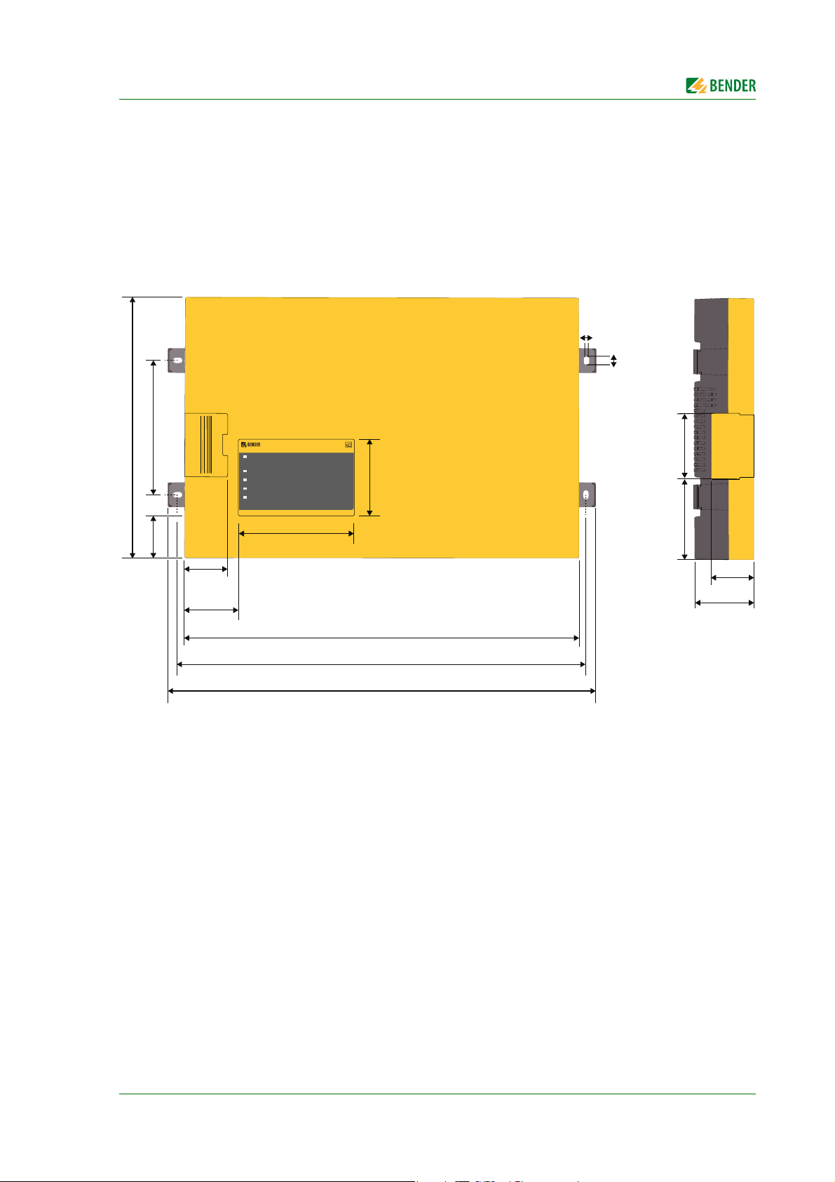
246 mm
125 mm40,5 mm
40,75 mm
51 mm
368 mm
383 mm
401,5 mm
106 mm
64 mm
8,75 mm
5,2 mm
61,8 mm
76,6 mm
39,8 mm
55,7 mm
4.1 Dimensions
iso1685FR(M)_D00002_02_M_XXEN/06.2017
19
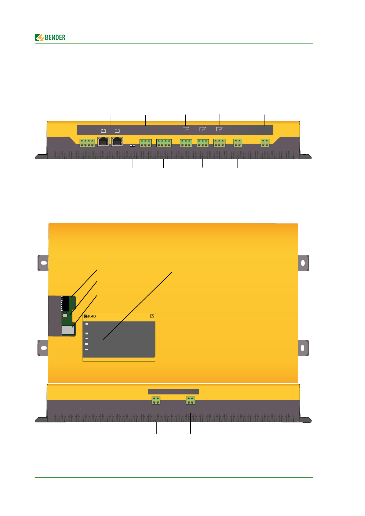
4.2 Connections
I2+
I2I1+
I1Digital input 1
starts manual self
est
RS-485 Term.
off
on
CAN 1
CAN 2
No function
A, B, S
RS-485 bus
connection (A,B)
Protocol:
iso1685FR: BMS
iso1685FRM:
BMS, Modbus RTU
k
I
kT
IT
no function
31, 32, 34
Relay output
for device error ("Service“
LED)
21, 22, 24
Relay output
for Alarm insulation fault
11, 12, 14
Relaiy output
for Alarm insulation
E, KE
Connection earth/reference.
Connect both to PE
A1, A2
Supply voltage DC24V.
Abritrary polarity
SERVICE
ALARM 2
ISOMETER
®
iso1685
ON
ALARM 1
PGH ON
LEDs:
- ON: Operation (flashes)
- PGH ON: No function
- SERVICE: Device error
- ALARM 1: Insulation fault
- ALARM 2: Insulation fault
DIP switch (SS8103)
Button (ST6101)
Memory card (SD card)
Coupling terminal L2/-.
Connection L1‘
Coupling terminal L1/+.
Connection (to) N conductor
Device overview
I2+ I2- I1+ I1-
I2+ I2- I1+ I1-
CAN 1
CAN 2
RS-485
Term .
o on
A B S
k I kT IT
K3 K2
21 22 2431 32 34k l kT ITA B S
31 32 34 21 22 24 11 12 14
K1
11 12 14
A1 A2E KE
E KE
A1 A2
20
L2/L- L1/L+
L1/+ L2/-
iso1685FR(M)_D00002_02_M_XXEN/06.2017
Device overview
µSDCard
SS8103
1
2
3
4
5
6
7
8
A4
A3
A2
A1
A0
ST6101
A4
A3
A2
A1
A0
1
2
3
4
5
6
7
8
A4
A3
A2
A1
A0
1
2
3
4
5
6
7
8
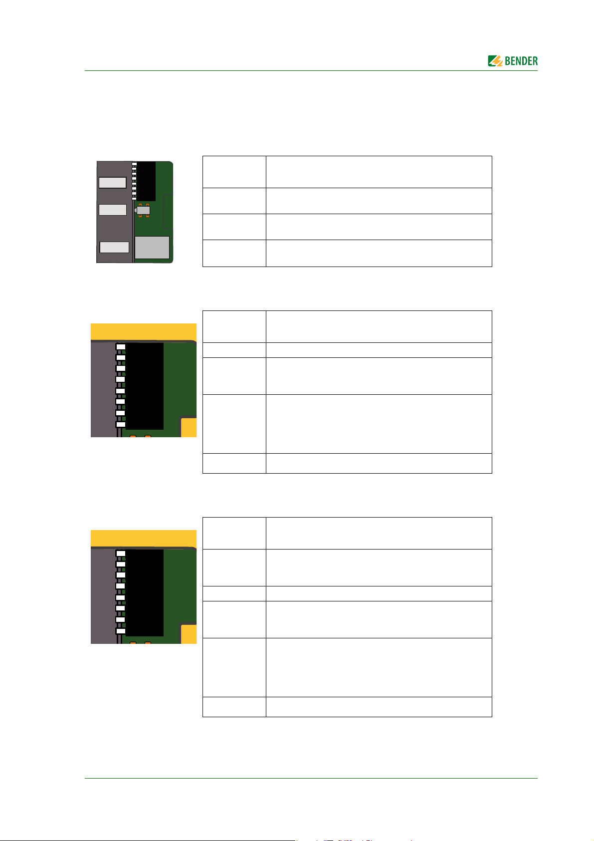
4.3 Display and operating elements
4.3.1 Operating elements
The representation below shows the position of the operating elements
Operating
elements
DIP switch
(SS8103)
Button
(ST6101)
Memory card
(SD Card)
Setting the BMS address
Reset device fault messages
Memory for log files and history memory (µSD card);
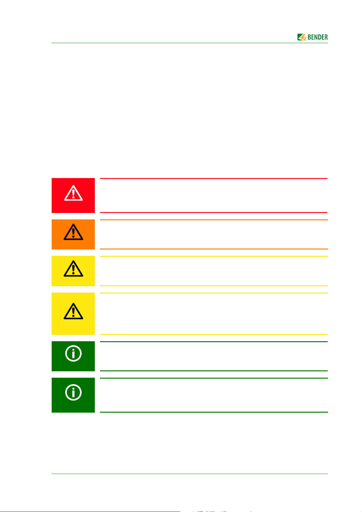
ISOMETER®s iso1685FR DIP swich assignment
DIP switch
number
1…5 Setting the BMS address
Locking the parameter function
6
7
ON = Parameter cannot be changed
OFF = Parameter can be changed
Device error notification when the SD card has not been
inserted
ON = Device error will be signalled.
The device-error relay K3 (31/32/34) does not switch!
OFF = Device error will NOT be signalled.
Function
Function
8Not used
ISOMETER®s iso1685FRM DIP switch assignment
DIP switch
number
Switching between BMS/Modbus RTU protocols
1
2…5 Setting BMS address
6
7
8Not used
iso1685FR(M)_D00002_02_M_XXEN/06.2017
ON = Modbus RTU
OFF = BMS
Locking the parameter function
ON = Parameter cannot be changed
OFF = Parameter can be changed
Device error notification when the SD card has not been
inserted
ON = Device error will be signalled.
The device-error relay K3 (31/32/34) does not switch!
OFF = Device error will NOT be signalled.
Function
21

4.3.2 Melde-LEDs auf dem Gehäuseoberteil
SERVICE
ALARM 2
ISOMETER
®
iso1685
ON
ALARM 1
PGH ON
LED Description
Power On indicator:
• Flashes with a pulse duty factor of approx. 80 % and 1 Hz.
ON
(green)
PGH ON
(green)
SERVICE
(yellow)
ALARM 1
(yellow)
ALARM 2
(yellow)
Device error:
• Lights continuously, when the device stops functioning (device stopped).
Software update:
• Flashes approx. three times faster during a firmware update: Update time < 4 minutes
No function
Internal device and connection error (system, earth):
Lights continuously.
Also refer to the list of error codes on page 31
Insulation fault:
Lights continuously when the insulation impedance falls below the response value Z
Passive methodLights continuously when the voltage U
überschreitet, U
N-PE
> U
an
Insulation fault 2 (alarm):
Lights continuously when the insulation impedance falls below the response value Ze < Z
Passive methodLights continuously when the voltage U
überschreitet, U
N-PE
> U
an
Device overview
e
exceeds the set response value Uan
N-PE
exceeds the set response value Uan
N-PE
< Z
an2
an2
22
iso1685FR(M)_D00002_02_M_XXEN/06.2017
5. Installation, connection and commissioning
DANGER
WARNING
CAUTION
CAUTION
5.1 Installation
Install the device using four M5 screws, refer also to the dimension diagram.Install the device so that it is in a
vertical position with the system coupling (L1/+, L2/–) positioned at the top when it is being operated.
5.2 Connection
All enclosed plug-in terminals are labelled.
5.2.1 Connection requirements
Risk of electric shock!
Touching uninsulated live conductors can result in death or serious injury. Therefore avoid
any physical contact with active conductors and ensure compliance with the regulations for
working on electrical installations.
Warning of insulation monitoring devices that do not work correctly!
Connect the terminals KE and E individually to the protective earth conductor PE.
Risk of injury from sharp-edged terminals!
Risk of lacerations. Touch the enclosure and the terminals with due care.
Risk of property damage due to unprofessional installation!
If more than one insulation monitoring device is connected to a conductively connected
system, the system can be damaged. If several devices are connected, the device does not
function and does not signal insulation faults. Make sure that only one insulation monitoring
device is connected in each conductively connected system.
Ensure disconnection from the IT system!
When insulation or voltage tests are to be carried out, the device must be isolated from the
system for the test period. Otherwise the device may be damaged.
Check proper connection!
Prior to commissioning of the installation, check that the device has been properly connected
and check the device functions. Perform a functional test using an earth fault via a suitable
resistance.
iso1685FR(M)_D00002_02_M_XXEN/06.2017
23

Installation, connection and commissioning
Prevent measurement errors!
When an AC system being monitored contains galvanically coupled DC circuits, take into
consideration that: an insulation fault can only be detected correctly when the rectifier valves
carry a minimum current of > 10 mA.
All terminals are pluggable push-wire terminals. Solid connecting wires can be directly
plugged in. For connection of flexible cables, the push-wire terminals must be pushed open by
pressing the corresponding orange interlocking mechanism with a flat-head screwdriver.
24
iso1685FR(M)_D00002_02_M_XXEN/06.2017
Installation, connection and commissioning
SER
VICE
ALA
RM 2
ISOMETER
®
is
o1685
ON
ALA
RM 1
PG
H ON
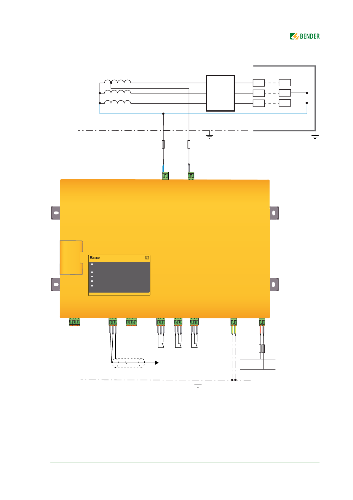
L1
L2
L3
N
U
S
6A
K1
K3
K2
31 32 34 11 12 1421 22 24
Thyristor
control
1
8
1
1
8
8
Heating elements
CVD reactor
DC 24 V
6A
3(N)AC 5 kV 50/60 Hz
PE
1A
1A
BMS master
2
L1‘
PE
k I kT IT
300 V
tap
I2+ I2- I1+ I1-
A1 A2E KE
L2/-L1/+
A B S
5.2.2 Wiring diagram with Modbus RTU (ISOMETER® iso 1685FR, iso1685FRM)
iso1685FR(M)_D00002_02_M_XXEN/06.2017
25

Installation, connection and commissioning
SER
VICE
ALA
RM 2
ISOMETER
®
is
o1685
ON
ALA
RM 1
PG
H ON
L1
L2
L3
N
U
S
6A
K1
K3
K2
31 32 34 11 12 1421 22 24
Thyristor
control
1
8
1
1
8
8
Heating elements
CVD reactor
DC 24 V
6A
3(N)AC 5 kV 50/60 Hz
PE
1A
1A
L1‘
PE
k I kT IT
300 V
tap
I2+ I2- I1+ I1-
mA
4…20 mA
A1 A2E KE
L2/-L1/+
A B S
ICP
CON
M
-7024
Iout0201
10 11
Iout1
Iout2
INIT*
(Y)DATA+
(G)DATA-
(R)+Vs
(B)GND
(Y)DATA+
(G)DATA-
(R)+Vs
(B)GND
Iout3
AGND
Iout0
AGND
AGND
Vout3
Vout2
Vout1
Vout0
DC power supply 1
24 V / 0.5 A
24 V GND
DC power supply 2
24 V / 0.5 A
24 V GND
5.2.3 Anschlussplan mit Modbus RTU (ISOMETER® iso1685FRM)
26
iso1685FR(M)_D00002_02_M_XXEN/06.2017

Installation, connection and commissioning
Te rm i na l,
Socket
I2+, I2–
I1+, I1–
A, B, S
k, l/kT, lT
31, 32, 34
21, 22, 24
11, 12, 14
E, KE
A1, A2
L1/+
L2/-
Connections
Digital input - currently has no function
Digital input - currently has no function
• Connection to BMS bus, RS-485, S= shielded (internally connected to PE), terminating switch
"RS-485 Term."
• Modbus RTU connection (iso1685FRM only)
No function
Alarm relay K3 for internal device errors and connection faults
Alarm relay K2 for insulation faults
Alarm relay K1 for insulation faults
Separate connection of E and KE to PE
Connection to Us = DC 24 V via fuses, 6 A each
Connection to N line
Connection to L1' (300 V tap)
5.2.4 Step-by-step connection of the ISOMETER®iso1685FR
Connect the device with the help of the connection and terminal diagram. Proceed as follows:
1. Connect terminal E and KE to earth (PE)
2. Connect terminal A and B to the BMS bus
3. Connect terminal S to the shield of the bus line (only to one end of the line)
4. Connect terminal L1/+ to the N conductor (neutral point) of the system to be monitored
5. Connect terminal L2/- to L1' (300 V tap) of the system to be monitored
6. Connect terminal A1/A2 to DC 24 V
7. Connect the signal outputs 11/12/14 and 21/22/24 (Insulation fault alarm for the active and passive
methods) and 31/32/34 (device error) for external signalling. The relay outputs 11/12/14 and 21/22/24
are implemented redundantly.
The coupling terminals L1/+ and L2/– are locked. To unplug the terminals, the orange sliders
must be slid towards the front (towards the device) to unlock the terminal. Now the terminal
can be unplugged.
iso1685FR(M)_D00002_02_M_XXEN/06.2017
27

Installation, connection and commissioning
5.2.5 Step-by-step connection of the iso1685FRM ISOMETER®
Connect the device with the help of the connection and terminal diagram. Proceed as follows:
1. Connect terminal E and KE to earth (PE)
2. BMS: Connect terminal A and B to the BMS bus
OR
Modbus RTUConnect terminal A to terminal (Y)DATA+ and terminal B to terminal (G)DATA- of the Modbus analog converter
3. When using the Modbus RTU interface:
"RS485 Term." switchSet (RS485-Terminierung) to "On".
4. Connect terminal L1/+ to the N conductor (neutral point) of the system to be monitored
5. Connect terminal L2/- to L1' (300 V tap) of the system to be monitored
6. Connect terminal A1/A2 to DC 24 V
7. Connect the signal outputs 11/12/14 and 21/22/24 (Insulation fault alarm for the active and passive
methods) and 31/32/34 (device error) for external signalling. The relay outputs 11/12/14 and 21/22/24
are implemented redundantly.
The coupling terminals L1/+ and L2/– are locked. To unplug the terminals, the orange sliders
must be slid towards the front (towards the device) to unlock the terminal. Now the terminal
can be unplugged.
The ISOMETER® must be switched on after or simultaneously with the Modbus analog converter.
5.3 Commissioning
Refer to "chapter 7.1.2 Parameter description" for further information concerning device parameterization.
28
iso1685FR(M)_D00002_02_M_XXEN/06.2017

Installation, connection and commissioning
System = IT System ?
Device connection
Un < 400 V ?
U
N-PE
< 3 kV, U
L1‘-PE
< 3kV ?
iso1685FR not suitableNo
Deenergize the installation before
connecting the device.
E and KE to PE
System to L1/+, L2/-
Optional device connection
BMS bus to A, B, S
Supply voltage to A1/A2
Signal peripherals at K1, K2, K3
11-12-14, 21-22-24, 31-32-34
Switch on supply voltage
Switch on mains voltage
No
Yes
ja
ja
iso1685FR not suitable
Connection fault or device error:
check the connections
Should factory settings
be kept?
No
Make the settings via the
BMS bus
Are the alarm LEDs
lighting?
No
Yes
The set response value is too low
- adjustment required
Function test with a suitable
ohmic resistance between the
system and earth. Value:
50% of the response value Z
an
Yes
No
Check connections
Remove resistance
The iso1685FR is connected
correctly and is functional
Alarm LEDs no longer lighting?
Alarm relays switched?
No
The iso1685FR successfully
carries out a self test
ja
No
ja
Are the alarm LEDs lighting?
Alarm relays switched?
5.3.1 Commissioning of the ISOMETER® iso1685FR
iso1685FR(M)_D00002_02_M_XXEN/06.2017
29

5.3.2 Commissioning of the ISOMETER® iso1685FRM
System = IT system ?
Yes
Un < 400 V ?
U
< 3 kV, U
N-PE
L1‘-PE
Yes
< 3kV ?
No
Yes
Deenergize the installation before
connecting the device.
iso1685FRM is not suitableNo
iso1685FRM is not suitable
Installation, connection and commissioning
Device connection
E and KE to PE
System to L1/+, L2/-
Supply voltage to A1/A2
Switch on supply voltage
Switch on mains voltage
The iso1685FRM successfully
carries out a self test
Yes
Should factory settings
be kept?
Yes
No
No
Optional device connection
BMS bus to A, B, S
Signal peripherals at K1, K2, K3
11-12-14, 21-22-24, 31-32-34
Connection fault or device error:
check the connections
Make the settings via the
BMS bus
Connect the iso685FRM to the
Analogue Modbus Converter
i.e. A to (Y)DATA+, B to (G)DATA-
Connect “(R)+Vs“ of the Analogue
Modbus Converter (M7024) to
“24 V“ of DC power supply 2, and
Connect “Iout0“ of the Analogue
Modbus Converter M7024 to the
“24 V“ of DC power supply 1
Connect the external analogue
input to “AGND“ of the Analogue
Modbus Converter M7024 and to
“GND“ of DC power supply 1
Analogue Modbus Converter:
Switch on the supply voltage
M7024:
“(B)GND“ to “GND“
Are the alarm LEDs
lighting?
No
Function test with a suitable
ohmic resistance between the
system and earth. Value:
50% of the response value Z
Are the alarm LEDs lighting?
Alarm relays switched?
Yes
Remove resistance
Alarm LEDs no longer lighting?
Alarm relays switched?
The iso1685FRM is connected
correctly and is functional
30
Yes
an
No
The set response value is too low
- adjustment required
Check connections
No
iso1685FR(M)_D00002_02_M_XXEN/06.2017

6. Device communication
S
CAN 2
S
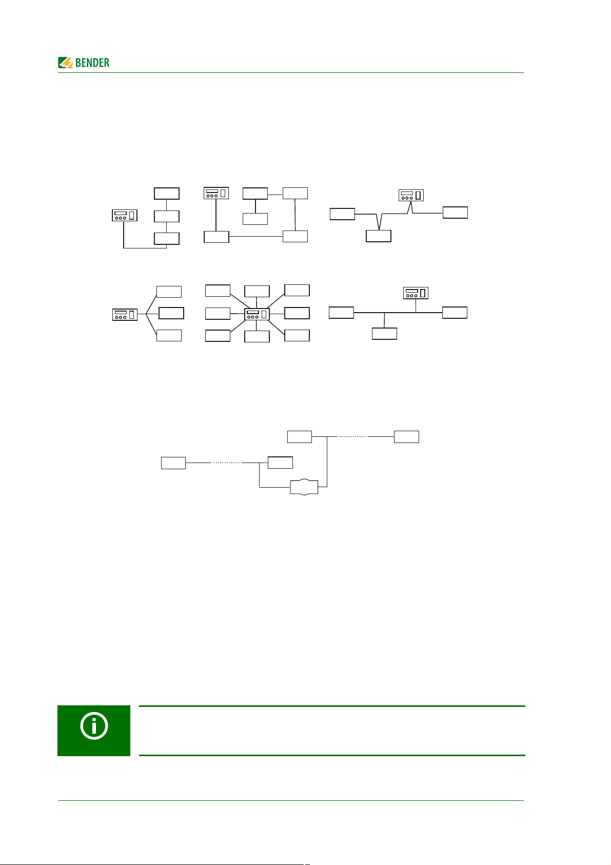
maximum length of the RS-485 network: 1200 m
1. device … device last device
stub feeder
max. 1 m
6.1 Device communication via the BMS bus
6.1.1 RS-485 interface with BMS protocol
The RS-485 interface, galvanically isolated from the device electronics, serves as a physical transmission medium for the BMS protocol (Bender measuring device interface). When one device or other bus-capable devices
are interconnected via the BMS bus in a network, the BMS bus must be terminated at both ends with a 120
resistor. For this purpose, the device is equipped with the terminating switch RS-485 Term. (off/on).
An RS-485 network that is not terminated is likely to become unstable and may result in malfunctions. Only the
first and last device in one line may be terminated. Stub feeders in the network (if any) must not be terminated.
The length of the stub feeders is restricted to 1 meter.
I2+ I2- I1+ I1-
I2+ I2- I1+ I1-
CAN 1
Abb. 6.1: Wiring and termination of the BMS bus with the device housing
iso1685FR(M)_D00002_02_M_XXEN/06.2017
k I kT IT
RS-485
Ter m .
o on
A B S
A B
K3 K2
21 22 2431 32 34k l kT ITA B S
31 32 34 21 22 24 11 12 14
A B S
A B
K1
11 12 14
A1 A2E KE
E KE
A1 A2
CAN 2
RS-485
CAN 2
Term.
o on
A B S
31
Device communication
DI1
1
32
33
64
6.1.2 Topology of the RS-485 network
The optimum topology for an RS-485 network is a daisy-chain connection. In this connection, device 1 is connected to device 2, device 2 to device 3, device 3 to device n etc. The RS-485 network represents a continuous
path without branches.
Correct arrangement
Three examples for correct arrangement:
Wrong arrangement
Three examples for wrong arrangement
Wiring
The following type of wiring is recommended for the RS-485 network:
≥Shielded cable, core diameter 0.8 (e.g. J-Y(St)Y 2x0.8), shield connected to earth (PE) at one end.
Connection to terminals A and B.
The number of bus nodes is restricted to 32 devices. If more devices are to be connected, Bender provides a DI1DL repeater.
6.1.3 BMS protocol
This protocol is an essential part of the Bender measuring device interface (BMS bus protocol). Data transmission generally makes use of ASCII characters.
Interface data are:
• Baud rate:9600 baud
• Transmission:1 start bit, 7 data bits, 1 parity bit, 1 stop bit (1, 7, E, 1)
• Parity:even
• Checksum:Sum of all transmitted bytes = 0 (without CR and LF)
The BMS bus protocol works according to the MASTER-SLAVE principle. Only one MASTER may exist in each network. All bus devices are identified by a unique BMS address. The MASTER cyclically scans all other slaves on the
bus, listens to their signals and then carries out the corresponding commands.
A device receives the MASTER function when it is assigned bus address 1.
The ISOMETER® can only be operated as a BMS SLAVE!
32
iso1685FR(M)_D00002_02_M_XXEN/06.2017
Device communication
O
A4
A3
A2
A1
A0
1
2
3
4
5
6
7
8
General description of a BMS Master
A master can query all measured values, alarm and operating messages from a slave.
If bus address 1 is assigned to a device, this device automatically represents the master, i.e. all addresses between 1 and 150 are cyclically scanned via the BMS bus for alarm and operating messages. If the master receives
no answer from 5 subsequent addresses, the scanning cycle will start again. If the master recognises incorrect
answers from a slave, the fault message "Fault RS-485" will be output via the BMS bus.
Fault causes may be:
• Addresses are assigned twice
• A second master exists on the BMS bus
• Interference signals occur on the bus lines
• A defective device is connected to the bus
• Terminating resistors are not activated or connected
6.1.4 Commissioning of an RS-485 network with BMS protocol
• Interconnect terminals A and B of all bus devices in one line
• Switch the terminating resistors on at the start and the end of the RS-485 network. If a device at the end
of the bus is not terminated, connect a 120 resistor to terminals A and B
• Switch the supply voltage on
• Assign the master function and address 1 to a bus-capable device
• Assign addresses (2...33) to all other bus devices in consecutive order.
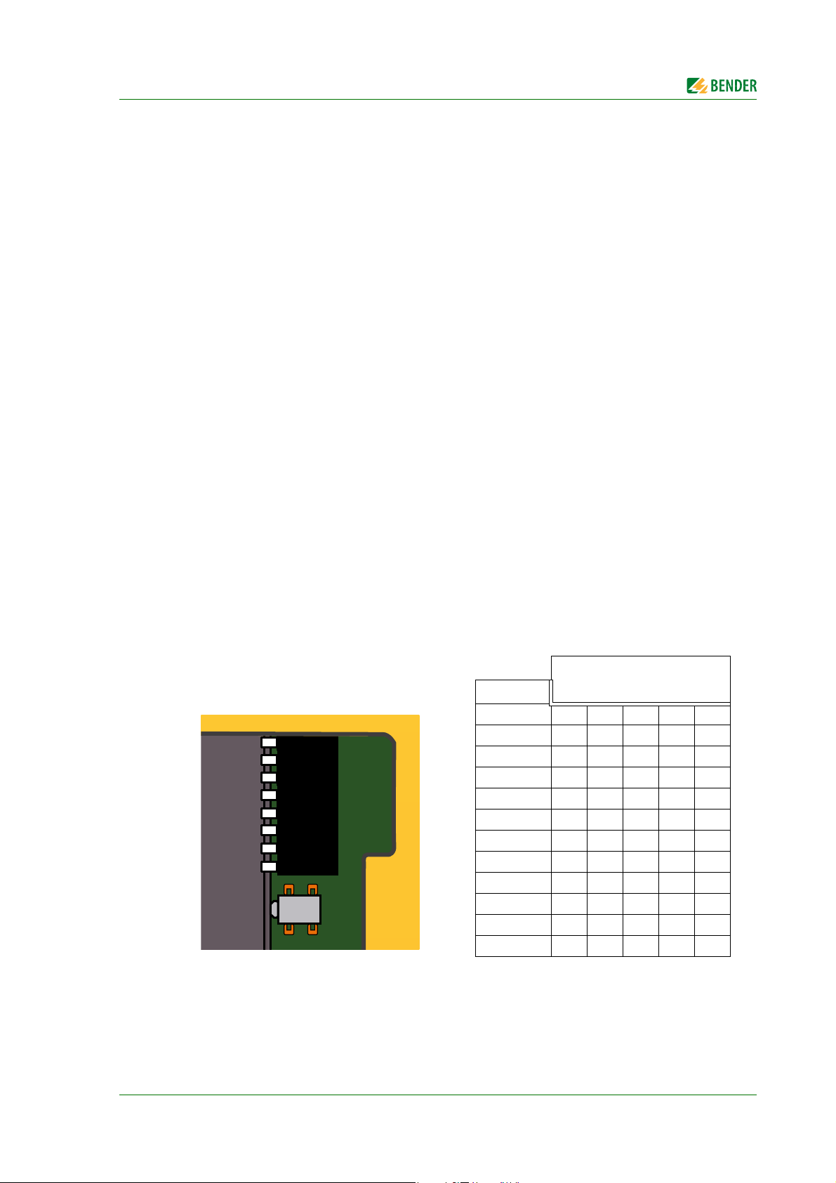
6.1.5 Setting BMS address
The factory setting of the BMS address can be changed using the DIP switch SS8103. Factory setting BMS address = 2
DIP-Schalter (SS8103)
BMS- Adr. A4 A3 A2 A1 A0
2 00000
3 00001
4 00010
5 00011
6 00100
7 00101
8 00110
9 00111
10 01000
.. .. .. .. .. ..
… ……………
33 11111
iso1685FR(M)_D00002_02_M_XXEN/06.2017
33

Device communication
6.1.6 Alarm and operating messages via the BMS bus
Messages are transmitted to a maximum of 12 BMS channels. All alarm and operating messages that may occur
are described below.
6.1.6.1 Alarm messages
Alarm Channel Meaning
Insulation fault alarm Ze/k 1
Insulation impedance < response value Z
(Active measuring method)
an
Alarm coupling 4 Terminal L1 and/or terminal L2 is not connected
Alarm E/KE 5 E-KE connection is not available
Device error alarm 7 Internal device error
alarm
U
N-PE
(Star point/earth)
Overtemperature coupling
terminal L1
Overtemperature coupling
terminal L2
8
10 Temperature of the coupling L1 > 150 °C
11 Temperature of the coupling L2 > 150 °C
Voltage U
> response value U
N-PE
(Passive measuring method)
an
6.1.6.2 Operating messages
Alarm Channel Meaning
Insulation impedance
Ze/k
System leakage capacitance
Ce/n
F
Insulation resistance
/k
R
e
Proposal C
Voltage U
eto-set
N-PE
(Star point/earth)
1
2
3
6 Proposal for the system capacitance
8
Temperature coupling L1 10 Temperature of the coupling L1 > 150 °C
Insulation impedance ≥ response value Z
Leakage capacitance C
Insulation resistance R
Voltage U
N-PE
in nF
e
in k
e
an
Temperature coupling L2 11 Temperature of the coupling L2 > 150 °C
Method by which the shutdown has occurred
• Active method
•Passive method
Method of shutdown
12
• Interference detection
34
iso1685FR(M)_D00002_02_M_XXEN/06.2017

Device communication
6.1.7 Error codes
The following list contains all relevant error codes output via the BMS bus. The right-hand column describes
the relevant action to be taken in each case.
The device error relay K3 (31, 32, 34) switches for all device errors with the sole exception of
error 3.10 in order to prevent a system shutdown in the event of an SD card error.
Error code Components Fault Action
0.30 Connection Connection earth (E/KE) Check connection
0.40 Connection Connection system (L1/+, L2/–) Check connection
Write access not possible
OR
3.10 Micro-SD card
8.11 Hardware Self test insulation measurement Contact service
8.12 Hardware Hardware measuring voltage source Replace device
8.42 Hardware Supply voltage ADC Replace device
8.43 Hardware Supply voltage +12 V Replace device
8.44 Hardware Supply voltage –12 V Replace device
8.45 Hardware Supply voltage +5 V Replace device
8.46 Hardware Supply voltage +3.3 V Replace device
8.47 Hardware Hardware Replace device
8.51 Hardware Monitoring the hardware temperature Replace device
8.52 Hardware Monitoring the sensor temperature Replace device
9.61
9.62 Calibration value System frequency analysis Calibrate device
9.65 Calibration value Measuring technique, ADC's Calibrate device
9.70 System General programme sequence Restart the device
Parameter,
calibration value
SD card has not been inserted
(when DIP switch 7 = ON)
Insulation measurement
Change the SD card
OR
Insert the SD card
or set the DIP switch 7 = OFF if
this message is not required.
Load factory settings, set parameters and calibrate
9.71 System
9.72 System
9.73 System
9.76 System Programme sequence history memory Restart the device
9.78 System Self test programme sequence Restart the device
9.80 Calibration Hardware Restart the device
9.81 System
9.82 System
iso1685FR(M)_D00002_02_M_XXEN/06.2017
Insulation measurement programme
sequence
Sytem frequency analysis programme
sequence
Voltage measurement programme
sequence
ADC channel U
ADC channel U
overload
n
overload
g
Restart the device
Restart the device
Restart the device
Check system/connection
Check system/connection
35

Device communication
Error code Components Fault Action
9.83 System
9.84 System
9.85 System
9.86 System
9.87 System
9.88 System
9.89 System
9.90 System
ADC channel U
ADC channel U1
ADC channel U
ADC channel U
ADC channel U
ADC channel U
ADC channel U1
ADC channel U
overload
E-KE
supply1
Tem p
posPE
overload
MVS
overload
PCP
supply2
negPE
overload
overload
overload
overload
overload
Check system/connection
Check system/connection
Check system/connection
Check system/connection
Check system/connection
Check system/connection
Check system/connection
Check system/connection
6.1.8 Resetting error messages
Recorded errors are provided as alarm messages on the BMS bus.
Pressing the reset button ST6101 will reset these error messages. If the fault continues to exist, the message will
be generated again.The error can also be reset by means of the acknowledgement command via the BMS bus.
6.1.9 Starting the firmware update via the BMS bus
The firmware can be updated via the BMS bus using the BMS Update Manager which can be obtained from
Bender.
can be obtained from Bender.
6.2 Device communication with Modbus RTU
The ISOMETER® iso1685FRM provides an analogue output by means of the Modbus-analogue converter.Communication takes place via Modbus RTU.
The Modbus RTU protocol can only be used for communication between the ISOMETER® and the Modbus analog converter.The Modbus RTU protocol is not available for further functions.
• The Modbus RTU protocol is activated with the ISOMETER® DIP switch
(see "chapter ISOMETER®s iso1685FRM DIP switch assignment").
• The wiring/connection diagram for the ISOMETER® iso1685FRM and Modbus analog converter can be
found under "chapter 5.2.3 Anschlussplan mit Modbus RTU (ISOMETER® iso1685FRM)". The connection
is also described in chapter "chapter 5.2.5 Step-by-step connection of the iso1685FRM ISOMETER®".
• For further information regarding commissioning, refer to
"chapter 5.3.2 Commissioning of the ISOMETER® iso1685FRM".
• Both the data sheet and manual of the Modbus analog converter M7024 contain further information
about the device and the Modbus protocol.You can find these documents on our homepage at
ICP DAS.
36
iso1685FR(M)_D00002_02_M_XXEN/06.2017

7. Parameterization via the BMS bus
7.1 Parameter
7.1.1 Tabel overview
BMS
Channel
comman
d
Description Setting range
1Ze/kO
Ce-instal-
2
3
4 MPT |Ze| measured data buffer size 1…10 (Default: 4, Step size: 1)
8EWL
9SFL
10 ANZ Monitoring of system coupling L,N
11 AER
12 SZL
lation
/nF
Re-instal-
lation
/kO
Response value for insulation measurment
(active method)
Ce value [nF] (Fixed),
(System leakage capacitance)
value [k] (Fixed)
R
e
System insulation fault
(Good condition)
Response value for insulation measurement
(passive method, threshold U
Response value for interference detection
over area [%]
Monitoring
E/KE coupling.
Number of interferences until a device error
[-]
an
[V])
10…1000 (Default: 25, Step size: 1)
1…200
(Default: 1, Step size: 1)
10…500 (Default: 180, Step size: 1)
0…3000 (Default: 125, Step size: 1
0 = disabled
0…50
(Default: 15, Step size: 1
0 = disabled
1: on (Monitoring enabled)
0: off (Monitoring disabled)
(Default: 1
1: on (Monitoring enabled)
0: off (Monitoring disabled)
(Default: 1
0…10 (Default: 6, Step size: 1
0 = disabled
7.1.2 Parameter description
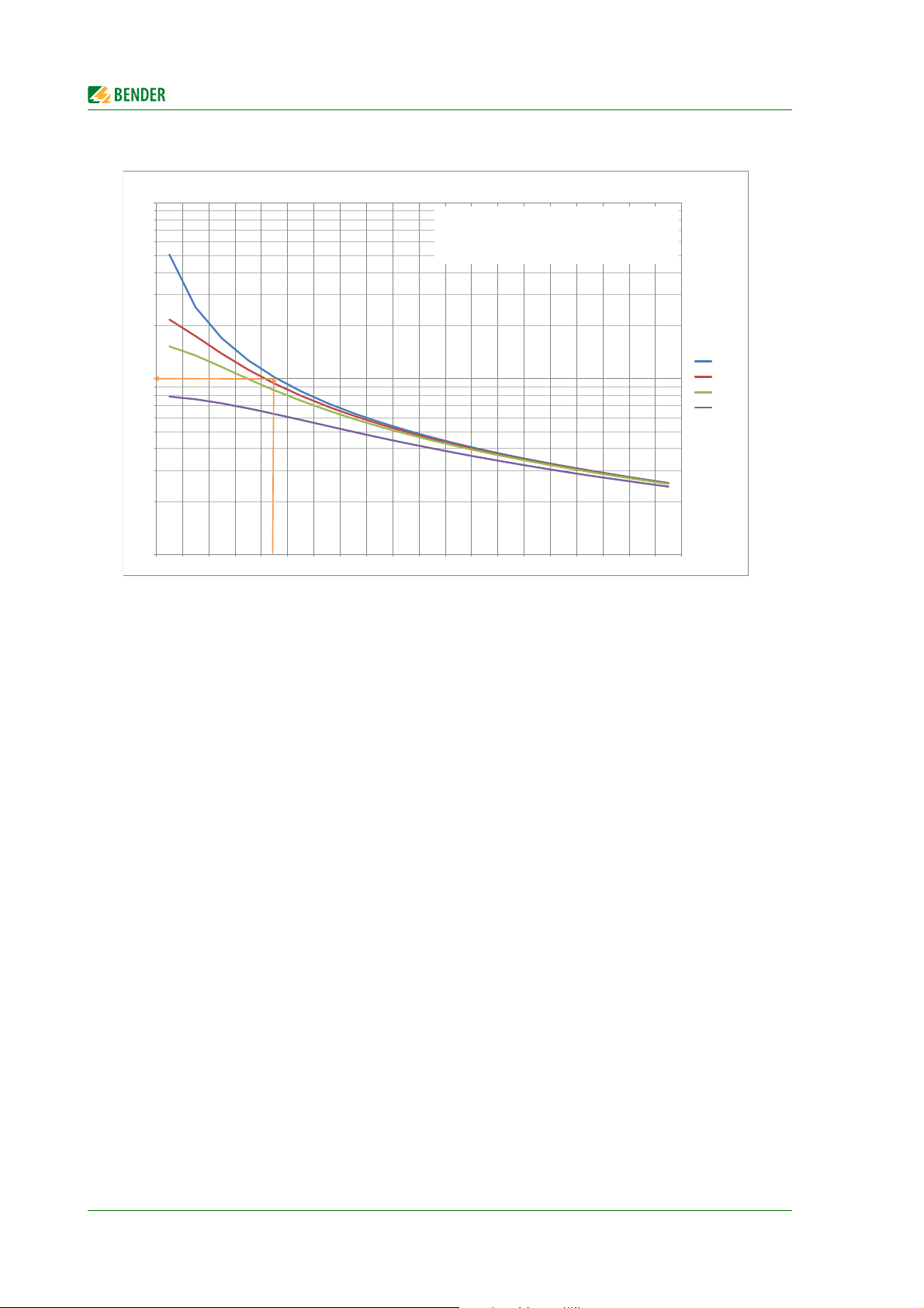
• Channel 1 (Zan/kΩ): Response value for insulation measurment (active method)
This parameter defines the response threshold for the active measurement procedure. If the insulation
value Z
alarm.
Depending on the system leakage capacitance C
the response value Z
ting condition taking into account the hysteresis (no alarm signal). The following diagram shows how
high the response value Z
iso1685FR(M)_D00002_02_M_XXEN/06.2017
measured by the ISOMETER® exceeds the response value Zan, then the ISOMETER® triggers an
e
and the system insulation resistance R
may not exceed a certain value so that the ISOMETER® enters the normal opera-
an
can be set for different insulation conditions of the installation.
an
e-Anlage
e-system
37
,
Parameterization via the BMS bus
10
100
1.000
10 20 30 40 50 60 70 80 90 100 110 120 130 140 150 160 170 180 190 200
Z
an-max
in Abhängigkeit der System-Ableitkapazität
>100M
300k
200k
100k
Z
an
/kΩ
C
e-Anlage
/nF
Beispiel:
Bei einer System-Ableitkapazität C
e-Anlage
von 50nF, darf der
Ansprechwert Z
an
maximal auf 100kΩ eingestellt werden.
(Annahme: System-Isolationsfehler R
e-Anlage
> 100MΩ)
R
e-Anlage
•
Channel 2 (C
e-Anlage/
nF) and channel 3 (R
e-Anlage
/kΩ): Insulation parameters during commissioning:
When the device is operated, the insulation condition of the installation can be stored as "good condition" via these two parameters.
• Channel 4 (MPT) Measured data buffer sizeThis parameter defines the buffer size for the measure-
ment results.The triggering time of the ISOMETER® depends linearly on the buffer size: A new measurement is entered into the buffer every 20 ms. The advantage of a higher buffer depth is that the
insulation level of the system can be determined more reliably.The disadvantage is that the reaction
time is extended.The larger the buffer size is set, the longer it takes for the mean value of the buffer entries to fall below the threshold value. A tripping time of 150 ms, as specified in the technical data,
applies to a maximum buffer size of 4 (factory setting).
• Channel 5 (FAN) Step-wise readjustment of the sampling frequency: Service parameters.
• Kanal 6 (CCN) Parameters for coupling monitoring of the N-conductor connection:
Service parameters.
• Kanal 7 (CCN) Parameters for coupling monitoring of the L-conductor connection:
Service parameters.
• Channel 8 (EWL – U
This parameter defines the response threshold for the passive measurement method. In the case of
unsymmetric insulation faults on one or more phases, an offset voltage develops between the star
point of the IT network and earth.If the offset voltage U
/V): Response offset voltage U
an
(passive method)
N-PE
exceeds the set response value Uan, the
N-PE
ISOMETER® triggers an alarm.
• Channel 9 (SFL): Measurement suppression response value (Interference detection active
method)
Interference detection is implemented for the active measuring method in order to prevent incorrect
measurements and therefore avoid false alarms.Active method interferences happen, for example,
because of spontaneous voltage spikes or voltage pulses in the network being monitored.The
ISOMETER® compares the voltage profile of successive network periods and discards the current determined measured value if the difference of the voltage profile considered exceeds the set response
value.
38
iso1685FR(M)_D00002_02_M_XXEN/06.2017

Parameterization via the BMS bus
• Channel 10 (ANZ): Coupling monitoring of the system connection
This parameter is used to switch off the coupling monitoring of the system connection
(terminals L1/L + and L2/L-).
• Channel 11 (AER): Coupling monitoring of the earth connection
This parameter is used to switch off the coupling monitoring of the earth connection (terminal E/KE).
• Channel 12 (SZL): Interference counter (actives method)
In addition to interference detection (see channel 9), the ISOMETER® can trigger a device error during a
prolonged fault.The SZL parameter is used to specify how many consecutive detected interferences
lead to a device error.This prevents the device from being "blind" due to interference - which means
that no measured values can be recorded for a long time.The sensitivity of the interference detection
can be parameterized via channel 9, and the maximum duration of the interference via channel 12.
7.2 Parameterization of the installation parameter Re-Anlage and Ce-Anlage
7.2.1 General information
The ISOMETER® monitors the impedance and not the purely ohmic insulation resistance of the installation.However, the purely resistive insulation resistance is also determined by means of the measured impedance
and the system leakage capacitance and can be requested.
In order to be able to determine the ohmic insulation resistance (R
lowing two parameters must be parameterized in the order shown during the initial commissioning of the installation using the iso1685FR tool set provided:
• Expected ohmic insulation resistance of the application during operation: R
• Expected system leakage capacitance of the application during operation: C
) of the network to be monitored, the fol-
e
[k]
e-Anlage
[nF]
e-Anlage
It is important that both parameters are set only once during the commissioning of a new installation and that
they cannot be changed during the lifetime.
Assuming a constant system leakage capacitance during the lifetime of the application, the ohmic insulation
resistance (R
) curve, determined by means of the set parameters provides a valid statement about the purely
e
ohmic insulation condition of the installation.
DIP switch 6 (SS8103) can be used to disable parameter changes.
• DIP switch 6 is set to ON = Parameters cannot be changed
• DIP switch 6 is set to OFF = Parameters can be changed
7.2.2 Parameterization with the iso1685FR-Set tool
The ISOMETER® can be parameterized with the iso1685FR-Set tool.
• You can download the software at:
http://www.bender-de.com/en/service-support/download/software.html
The iso1685FR-Set tool can only be used if there is no master in the BMS system.
iso1685FR(M)_D00002_02_M_XXEN/06.2017
39

By using the iso1685FR-Set program you confirm the following conditions:
Bender provides this software free of charge and without any warranty. By using this software
you agree that you are using the software at your own risk. Bender does not assume any responsibility for possible software errors or defects and does not guarantee that the software
works error-free and reliably. Furthermore, Bender does not accept liability for direct or indirect damage that may arise from the use of the software.
7.2.3 Error handling
Parameterization via the BMS bus
If the displayed values do not correspond to the conditions of the installation after parameterization, R
and C
e-Anlage
must be set again. Refer to the iso1685FR-Set quickstart for operating instructions.
e-Anlage
If the parameters do not correspond with the conditions of the installation, an ohmic insulation value deviating
from R
e_Anlage
is output for Re instead of the real value after initial commissioning.If the value of Re cannot be
determined, a default value of 1 M is output instead.
The following errors can lead to these deviating outputs:
• Incorrect parameterization of R
e_Anlage
Consequences: The value to be parameterized for C
:
e_Anlage
(= Ce to set) cannot be correctly determined. Error cases: a.) Ohmic insulation resistance of the installation is higher than the parameterized
value:
Output R
Error handling: R
= 1 M
e
e_Anlage
and C
e_Anlage
must be parameterized again
b.) Ohmic insulation resistance of the installation is LOWER than the parameterized value: Output
R
= Re = 1 M:
e
Error handling: R
e_Anlage
• Incorrect parameterization of C
and C
e_Anlage
e_Anlage
must be parameterized again
:
Consequences: The resulting ohmic insulation resistance value does not correspond to the expected
value of the installation.
Error cases:
a.) System leakage capacitance of the installation is HIGHER than the parameterized value:
Output R
Error handling: C
≠ R
e
e_Anlage
e_Anlage
must be parameterized again
b.)System leakage capacitance of the installation is LOWER than the parameterized value:
Output R
Error handling: C
= 1 M
e
e_Anlage
must be parameterized again
40
iso1685FR(M)_D00002_02_M_XXEN/06.2017
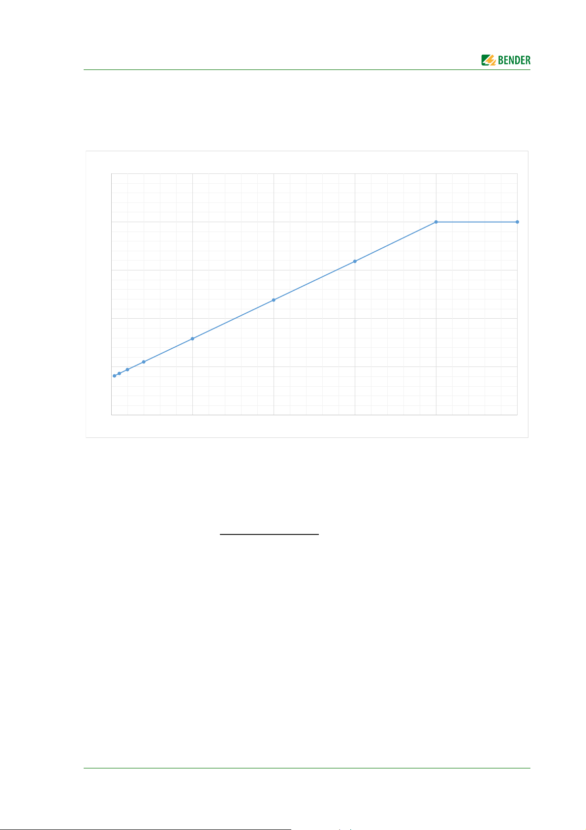
8. Diagram for the calculation of Z
0
5
10
15
20
25
0 50 100 150 200 250
iso1685FRM: M-7024
[kΩ]
[mA]
Ze[kΩ] =
((I
a
[mA] - 4) * 200)
16
e
The following formula for calculating the insulation value measured by ISOMETER® is applicable for
Z
≤ 200 k.
e
iso1685FR(M)_D00002_02_M_XXEN/06.2017
41

Diagram for the calculation of Ze
42
iso1685FR(M)_D00002_02_M_XXEN/06.2017

9. Information about the measuring method
The device can report an insulation fault or a permanent interference via the following methods:
• Active method parameter:Response value Z
• Passive method parameter:Response value U
• Interference detection parameter: Interference level (SFL), number of interferences until a device error
(SZL) can be switched off by setting SZL to 0
Coupling monitoring
• Monitoring a coupling network: switched off
• Monitoring PE coupling (E/KE).switched off
Useful default settings:
• Active methodResponse value: 25 k; Measuring buffer depth:4
• Passive methodResponse value: 200 V
• Interference detection: Degree of interference: 20 %; Number of interferences until a device error:6
(120 ms)
Important:
When interference detection is switched off, the shutdown time of the active method is somewhat longer for phase faults because the disturbed measured values from the switching moment are registered
in the measuring buffer.
When interference detection is activated, the shutdown times are at least 20 ms shorter because the disturbed measured values are discarded.
, Measured data buffer size cannot be switched off
an
can be switched off by setting Uan to 0
an
In the case of continuous interference, the device can only trigger via either the passive method or the
interference detection.
iso1685FR(M)_D00002_02_M_XXEN/06.2017
43

Information about the measuring method
44
iso1685FR(M)_D00002_02_M_XXEN/06.2017

10. Technical data
10.1 Tabular data
Insulation coordination acc. to IEC 60664-1 / IEC 60664-3
Insulation coordination according to IEC 60664-1
Rated insulation voltage (terminals L1/L2 to E/KE) .............................................................................................................................................................................. 5 kV
Overvoltage category .................................................................................................................................................................................................................................... II
Pollution degree ........................................................................................................................................................................................................................................... 2
Voltage ranges
Nominal system voltage U
Phase-to-phase voltage .............................................................................................................................................................................................................AC 0…5 kV
Voltage component L1/+ to PE (U
Voltage component L2/- to PE (U
Supply voltage U
Power consumption ............................................................................................................................................................................................................................. ≤ 7 W
Power consumption .......................................................................................................................................................................................................................... ≤ 7 VA
Measuring circuit for insulation monitoring
Measuring voltage U
Measuring current I
Internal DC resistance R
Impedance Z
at 50 Hz.................................................................................................................................................................................................................... ≥ 260 kΩ
i
Permissible extraneous DC voltage U
Permissible system leakage capacitance C
Response values for insulation monitoring (active method)
Response value Z
Relative uncertainty (100 kΩ…1 MΩ) (acc. to IEC 61557-8:2007-01) ........................................................................................................................................... ±15 %
Relative uncertainty (10…100 kΩ).................................................................................................................................................................................... ± 5 kΩ
Response time t
an
Hysteresis................................................................................................................................................................................................................................................ 25 %
L1+/L2-................................................................................................................................................................................. AC 0…400 V**
n
) ........................................................................................................................................................................... AC 0…3 kV***
N-PE
) ............................................................................................................................................................................ AC 0…3 kV***
(Also refer to the device name plate) ...................................................................................................................................................... DC 18…30 V
S
(effective value) ................................................................................................................................................................................................. 34 V
m
(when Re = 0 Ω) ........................................................................................................................................................................................ ≤ 150 A
m
(Alarm) ................................................................................................................................................................................... 10…1000 kΩ (25 kΩ)*
an
L1‘-PE
................................................................................................................................................................................................................. ≥ 260 kΩ
i
.................................................................................................................................................................................................... 0 V
fg
................................................................................................................................................................................... ≤ 200 nF
e
± 15 %
(for measurement buffer size MPT = 3) ........................................................................................................................................................ ≤ 150 ms
Response values for insulation monitoring (passive method)
Response value U
(Alarm) ....................................................................................................................................................................................... 0…3000 V (125 V)*
an
Relative uncertainty (100…3000 V)................................................................................................................................................................................................. ± 5 %
Relative uncertainty (1…100 V.............................................................................................................................................................................................. ± 5 V
Response time t
(for measurement buffer size MPT = 3) ........................................................................................................................................................ ≤ 150 ms
an
± 5 %
Hysteresis................................................................................................................................................................................................................................................ 25 %
Displays, memory
LEDs for alarms and operating states ........................................................................................................................................................................... 1 x green, 3 x yellow
µSD card for history memory and log files ...................................................................................................................................................................................... ≤ 32 GB
Digital inputs
I1+, I1- (high active) ....................................................................................................................................................................................................................no function
I2+, I2- .........................................................................................................................................................................................................................................no function
Analog output (via ICP M-7024 Modbus analog converter):
Number.......................................................................................................................................................................................................................................................... 1
Operating principle............................................................................................................................................................................. linear, 0…200 kΩ (refer to diagram)
Function .............................................................................................................................................................................................................................insulation value Z
Current ....................................................................................................................................................................................................................... 4…20 mA (< 600 Ω)
Tolerance ............................................................................................................................................................................................................................................. ±10 %
iso1685FR(M)_D00002_02_M_XXEN/06.2017
45
e

Technical data
Serial interfaces
Interface/protocol iso1685FR....................................................................................................................................................................................... RS-485 / BMS (slave)
Interface/protocol iso1685FRM ......................................................................................................................................RS-485 / BMS (Slave), Modbus RTU (switchable)
Connection........................................................................................................................................................................................................................ bus: Terminals A/B
.............................................................................................................................................................................................................................................Shield: Terminal S
Cable length ................................................................................................................................................................................................................................. ≤ 1200 m
Shielded cable (shield to PE on one side)......................................................................................................................................2-core, Ø 0.6 mm
2
, e.g. J-Y(St)Y 2 x 0.6
Terminating resistor, switchable (switch RS-485 Term.) ...................................................................................................................................................... 120 Ω (0.5 W)
Device address, BMS bus, adjustable (DIP switch) iso1685FR ................................................................................................................................................. 2…33 (2)*
Device address, BMS bus, adjustable (DIP switch) iso1685FRM ............................................................................................................................................. 2…17 (2)*
Switching elements
Switching elements............................................................................... 3 changeover contacts: K1 (insulation fault), K2 (insulation fault redundant), K3 (device error)
Operating principle K1, K2 .............................................................................................................................................. ............................. N/C operation, not changeable
Operating principle K3 ........................................................................................................................... ................................................ N/C operation, cannot be changed
Contact data acc. to IEC 60947-5-1:
Utilisation category ................................................................................................................................................................................. AC 13 AC 14 DC-12 DC-12 DC-12
Rated operational voltage .............................................................................................................................................................................. 230 V 230 V24 V110 V220 V
Rated operational current......................................................................................................................................................................................... 5 A 3 A 1 A 0.2 A 0.1 A
Minimum contact rating .......................................................................................................................................................................................... 1 mA at AC/DC ≥ 10 V
Connection via terminals (except system coupling)
Connection type........................................................................................................................................................................................... pluggable push-wire terminals
Connection, rigid/flexible.......................................................................................................................................................................... 0.2…2.5 mm
2
/0.2…2.5 mm
Connection flexible with connector sleeve, without/with plastic sleeve .......................................................................................................................... 0.25…2.5 mm
Conductor sizes (AWG) ..................................................................................................................................................................................................................... 24…12
2
2
Connection of the system coupling
Connection type........................................................................................................................................................................................... pluggable push-wire terminals
Connection, rigid/flexible............................................................................................................................................................................. 0.2…10 mm
2
/ 0.2…6 mm
Connection, flexible with ferrules, without/with plastic sleeve ............................................................................................................... 0.25…6 mm2/0.25…4 mm
Connection AWG/kcmil...................................................................................................................................................................................................................... min. 24
Conductor cross section AWG/kcmil ................................................................................................................................................................................................... max. 8
Environmental conditions
EMC EN 61326-2-4
EMC except, IEC 61000-4-3 (Radiated immunity 80MHz - 1GHz): .....................................................................................................................................................8V/m
Ambient temperatures:
Operating temperature........................................................................................................................................................................................................... -25…+ 70 °C
Transport................................................................................................................................................................................................................................. -25…+ 80 °C
Long-term storage ................................................................................................................................................................................................................. -25…+ 80 °C
Classification of climatic conditions acc. to IEC 60721:
Stationary use (IEC 60721-3-3) ........................................................................................................................................ 3K5 (except condensation and formation of ice)
Transport (IEC 60721-3-2) ...................................................................................................................................................................................................................... 2K3
Long-time storage (IEC 60721-3-1)........................................................................................................................................................................................................ 1K4
Classification of mechanical conditions acc. to IEC 60721:
Stationary use (IEC 60721-3-3) ............................................................................................................................................................................................................... 3M4
Transport (IEC 60721-3-2).......................................................................................................................................................................................................................2M2
Long-term storage (IEC 60721-3-1) ..................................................................................................................................................................................................... 1M3
2
2
46
iso1685FR(M)_D00002_02_M_XXEN/06.2017

Technical data
Other
Operating mode .......................................................................................................................................................................................................... continuous operation
Position of normal use................................................................................................................................................................................ vertical, system coupling on top
Degreee of protection, internal components.......................................................................................................................................................................................... IP30
Degree of protection, terminals .............................................................................................................................................................................................................. IP30
Software version ......................................................................................................................................................................................................................... D407 V1.13
Weight ................................................................................................................................................................................................................................................... 650 g
( )* = ......................................................................................................................................................................................................................................Factory settings
** = The specification refers only to the differential voltage between the coupling terminals, not to earth.
Higher voltages lead to a device fault notification (ADC overload), but not to a defect in the device.Maximum
permissible voltage between terminals L1 and L2 = 3.0 kV
*** =Corresponds to a maximum phase voltage of the system to be monitored of 5 kV.
10.2 Factory settings
Parameter Software
Insulation measurement response value Z
(Active method)
Leakage capacitance of the installation C
Insulation resistance of the installation R
Measured data buffer size for |Ze| (active method)
Offset voltage response value U
(passive method)
Response value of measured value suppression
(Interference detection active method)
Coupling monitoring system connection
Monitoring earth connection E/KE 1 (Monitoring enabled) BMS
Response value of the interference counter (actives
method)
Relay K1 (11/12/14) N/C operation -
Relay K2 (21/22/24) N/C operation -
BMS address 2 DIP switch
Parameterization lock OFF (Lock off) DIP switch 6
BMS termination ON (Termination enabled)
an
an
e-Anlage
e-Anlage
1 (Monitoring enabled) BMS
Value
Condition
25 k BMS
1 nF BMS
180 k BMS
4BMS
125 V BMS
15 % BMS
6BMS
can be set via
Switch
"RS-485-Term."
Relay K3 (31/32/34) N/C operation -
Special faetures of the iso1685FRM
RS485 protocol Value can be set via
BMS OFF DIP switch 1
iso1685FR(M)_D00002_02_M_XXEN/06.2017
47
10.3 Standards and certifications
The ISOMETER® has been developed in compliance with the following standards:
• DIN EN 61557-8 (VDE 0413-8)
• IEC 61557-8
• IEC 61326-2-4
• DIN EN 60664-1 (VDE 0110-1)
• EN 50178:1998-04
10.4 Ordering details
Technical data
Typ e
iso1685FR-525
iso1685FRM-525
The data labelled with an * are absolute values
Response value range
10 k…1000 k AC 0…400 V DC 18…30 V
10 k…1000 k AC 0…400 V DC 18…30 V
Nominal
voltage
Supply voltage *
Communication Art. No.
BMS B91065800
BMS /
Modbus RTU
B91065804
48
iso1685FR(M)_D00002_02_M_XXEN/06.2017

INDEX
A
Adresseinstellung 13
Alarm messages
Alarm relays K1, K2, K3
Anschluss
- Anschlussbedingungen
- Anschlussplan
- Schrittweiser Anschluss
Anzeige
Arbeiten an elektrischen Anlagen
34
17
23
26
27
21
B
Bedienelemente 21
Bestellangaben
Betriebsmeldungen
BMS bus
- Alarm messages
- Commissioning
- Number of bus nodes
- Protocol
- Setting BMS address
- Slave
- Termination
- Wiring
BMS-Bus
- Betriebsmeldungen
- Master
- Terminierung
- Verdrahtung 31
Button
48
34
34
33
32
32
33
32
31
31
34
33
31
21
12
F
Fehlermeldungen zurücksetzen 36
Firmware update
Functional description
36
16
G
Gerätemerkmale 15
Geräteübersicht
19
H
History memory 17
I
Inbetriebnahmeschema 29
Insulation monitoring
iso1685FR set
16
39
K
Kennlinien 48
M
Maßbild 19
Measured value transmission
Memory card
Montage des Geräts
16, 17, 21
17
23
N
Normen 48
R
RS-485 interface 31
RS-485 network
- Correct arrangement
- Terminated network
RS485-Netzwerk
- Falsche Verlegung
- Verdrahtung
32
31
32
32
S
Selbsttest
- manueller Selbsttest
Self test
- after connection to the supply volta-
17
ge
Sicherheitshinweise
Software iso1685FR set
19
12
39
T
Technische Daten 45
Terminating resistor
Terminierung
31
13
W
Werkseinstellungen 43
Z
Zulassungen 48
C
Commissioning 28
D
DIP switch 21
DIP-Schalter-Belegung
21
E
Error codes 35
iso1685FR(M)_D00002_02_M_XXEN/06.2017
O
Operating elements
21
- Button
- DIP switch
- Memory card
21
P
Parameterization 39
- Error handling
Parametrierung
- Fehlerhandling
21
40
40
49

INDEX
50
iso1685FR(M)_D00002_02_M_XXEN/06.2017

INDEX
iso1685FR(M)_D00002_02_M_XXEN/06.2017
51

Bender GmbH & Co. KG
Postfach 1161 • 35301 Grünberg • Germany
Londorfer Straße 65 • 35305 Grünberg • Germany
Tel.: +49 6401 807-0 • Fax: +49 6401 807-259
E-Mail: info@bender.de • www.bender.de
Fotos: Bender archiv.
BENDER Group
 Loading...