

Page 1
A-ISOMETER® IR425
Isolationsüberwachungsgerät
Deutsch English
Bestimmungsgemäße Verwendung
Das A-ISOMETER® IR425 überwacht den Isolationswiderstand R
eines ungeerdeten AC/DC-Steuerstromkreises (IT-System) von
AC 0...300 V bzw. DC 0...300 V. Die zulässige Netzableitkapazität
max beträgt 20 µF.
C
e
Sicherheitshinweise allgemein
Bestandteil der Gerätedokumentation sind neben diesem Datenblatt die beiliegenden „Wichtigen sicherheitstechnischen Hinweise für Bender-Produkte“.
Sicherheitshinweise gerätespezifisch
In jedem leitend verbundenen System darf nur ein
Isolationsüberwachungsgerät angeschlossen sein.
Vor Isolations- und Spannungsprüfungen an der Anlage muss das Isolationsüberwachungsgerät für die
Dauer der Prüfung vom IT-System getrennt sein.
Funktionsbeschreibung
Das A-ISOMETER® IR425 erzeugt eine pulsierende Messspannung. Diese wird über die Klemmen L1/L2 und KE/E dem zu überwachenden IT-System überlagert. Ohmsche Isolationsfehler
zwischen IT-System und Erde schließen den Messkreis. Der aktuelle gemessene Isolationswiderstand wird auf dem Display des
Geräts angezeigt.
Preset-Funktion
Nach erstem Anlegen der Versorgungsspannung U
koppeltem IT-System werden die Ansprechwerte R
(Alarm 1/2) einmalig automatisch auf folgende Werte gesetzt:
> 72 V: Ansprechwert 1 = 46 kΩ, Ansprechwert 2 = 23 kΩ
U
n
≤ 72 V: Ansprechwert 1 = 20 kΩ, Ansprechwert 2 = 10 kΩ
U
n
Die Preset-Funktion wird nach Rücksetzen auf die Werkseinstellungen erneut ausgeführt.
Selbsttest, automatisch
Das Gerät führt nach dem Zuschalten der Versorgungsspannung
und danach alle 24 h einen Selbsttest durch, bei dem interne
U
S
Funktionsstörungen oder Anschlussfehler ermittelt und als Fehlercode auf dem Display angezeigt werden. Die Alarm-Relais werden dabei nicht geprüft.
Selbsttest, manuell
Durch Betätigen der internen/externen Testtaste > 1,5 s führt das
Gerät einen Selbsttest durch, bei dem interne Funktionsstörungen oder Anschlussfehler ermittelt und als Fehlercode auf dem
Display angezeigt werden. Die Alarm-Relais werden dabei geprüft.
Während des Drückens der Test-Taste werden alle für dieses Gerät verfügbaren Display-Elemente angezeigt.
Funktionsstörung
Liegt eine Funktionsstörung vor, schaltet Relais K2 (21, 22, 24)
und alle 3 LEDs blinken. Das Display zeigt einen Fehlercode.
E01 = Schutzleiter-Anschluss fehlerhaft, keine niederohmige
Verbindung zwischen E und KE.
E02 = Netz-Anschlussfehler, keine niederohmige Verbindung
zwischen L1 und L2.
E03...Exx = Interner Gerätefehler
und ange-
S
an1/Ran2
Insulation monitoring device
Intended use
F
The IR425 A-ISOMETER® monitors the insulation resistance of an
unearthed AC or DC control circuit (IT system) of AC 0...300 V respectively DC 0...300 V. The maximum permissible system leakage capacitance C
is 20 µF.
e
Safety instructions
In addition to this data sheet, the documentation of the device includes a sheet entitled "Important safety instructions for BENDER
products".
Device-specific safety information
Only one insulation monitoring device may be used
in each interconnected system.
When insulation and voltage tests are to be carried
out, the device shall be isolated from the system for
the test period.
Function
The IR425 A-ISOMETER® generates a pulsating measuring voltage which is superimposed on the IT system being monitored via
the terminals L1/L2 and KE/earth. Ohmic insulation faults close
the measuring circuit between the IT system and earth. The currently measured insulation resistance is shown on the display of
the device.
Preset function
After connecting the supply voltage U
tem for the first time, the response values R
are automatically set once to:
> 72 V: response value 1 = 46 kΩ, response value 2 = 23 kΩ
U
n
≤ 72 V: response value 1 = 20 kΩ, response value 2 = 10 kΩ
U
n
After resetting the device values to its factory settings, the Preset
function is automatically active again.
Automatic self test
The device automatically carries out a self test after connecting to
the supply voltage U
test, internal functional faults or connection faults will be determined and will appear in form of an error code on the display. The
alarm relays are not checked during this test.
Manual self test
After pressing the internal/external test button for > 1.5 s, the device carries out a self test. During this test, internal functional
faults, or connection faults will be determined and will appear in
form of an error code on the display. The alarm relays are checked
during this test.
With the test button pressed and held down, all device-related
display elements appear on the display.
Malfunction
In case of a malfunction, the relay K2 (21, 22, 24) switches and all
of the three LEDs flash. An error code appears on the display.
E01 = PE connection fault, no low-resistance
connection between E and KE.
E02 = system connection fault, no low-resistance connection
between L1 and L2.
E03...Exx = internal device error
and later every 24 hours. During the self
S
and connecting the IT sys-
S
an1/Ran2
(Alarm 1/2)
TBP103005 / 09.2010
1
Page 2
A-ISOMETER® IR425
Verzögerungszeiten t und t
on
Die nachfolgend beschriebenen Zeiten t und ton verzögern die
Ausgabe von Alarmen über LEDs und Relais.
Anlaufverzögerung t
Nach Zuschalten der Versorgungsspannung U
wird die Ausgabe
S
von Alarmen um die eingestellte Zeit t (0...10 s) verzögert.
Ansprechverzögerung t
on
Bei Unterschreiten eines Ansprechwerts Ran benötigt das
A-ISOMETER in Abhängigkeit vom überwachten IT-System bis zur
Ausgabe eines Alarms die Ansprechzeit t
.
an
Eine eingestellte Ansprechverzögerung ton (0...99 s) addiert sich
zur systembedingten Ansprechzeit tan und zögert die Signalisierung hinaus (Gesamtverzögerung = t
+ ton).
an
Besteht der Isolationsfehler während der Ansprechverzögerung
nicht weiter, entfällt die Signalisierung des Alarms.
Passwort-Schutz (on, OFF)
Wurde der Passwort-Schutz aktiviert (on), können Einstellungen
nur nach Eingabe des korrekten Passworts (0...999) vorgenommen werden.
Werkseinstellung FAC
Nach Aktivieren der Werkseinstellung werden alle geänderten
Einstellungen auf den Auslieferungszustand zurückgesetzt. Zusätzlich erfolgt die automatische Anpassung der Ansprechwerte
in Abhängigkeit von der Nennspannung Un.
R
an
Montage und Anschluss
Time delays t and t
on
The times t and ton described below delay the indication of
alarms via LEDs and relays.
Starting delay t
After connection to the supply voltage U
the alarm indication is
S,
delayed by the preset time t (0...10 s).
Response delay t
on
When the value falls below the set response value Ran, the A-ISOMETER delays the alarm indication by the response time tan corresponding to the IT system being monitored.
Both the set response delay t
(0...99 s) and the system-related
on
response time tan delay the alarm indication
(total delay= t
+ ton).
an
If the insulation fault does not continue to exist during the response delay, no alarm will be signalled.
Password protection (on, OFF)
When password protection has been activated (on), settings can
only be carried out after entering the correct password
(0...999).
Factory setting FAC
After activating the factory setting, all settings previously
changed are reset to delivery status. In addition, the response val-
are automatically adapted corresponding to the nominal
ues R
an
voltage Un.
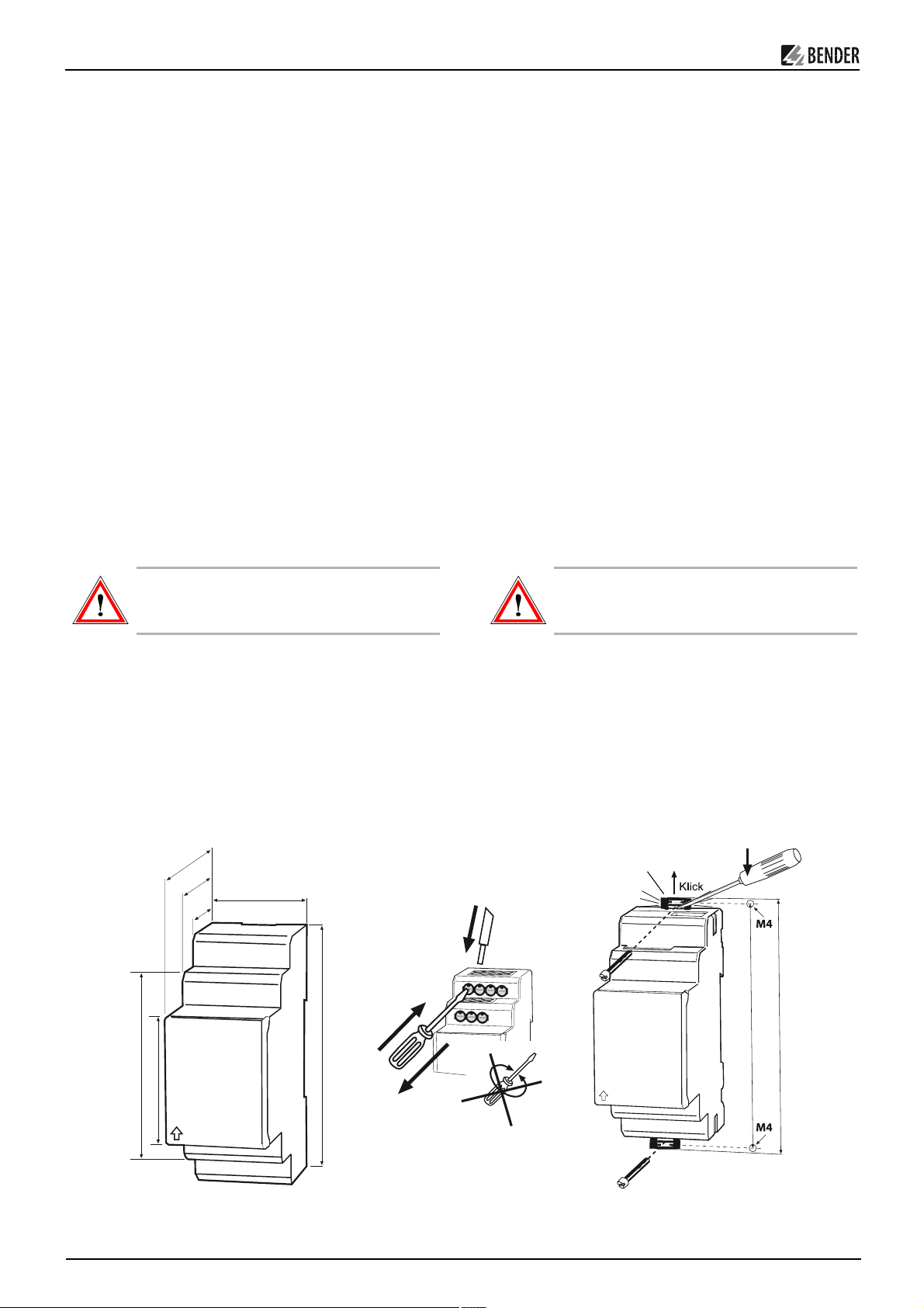
Installation and connection
Sorgen Sie für Spannungsfreiheit im Montagebereich
und beachten Sie die Regeln für das Arbeiten an elektrischen Anlagen.
1. Montage auf Hutschiene:
Rasten Sie die rückseitigen Montageclip des Geräts auf der
Hutschiene so ein, dass ein sicherer und fester Sitz gewährleistet ist.
Schraub-Befestigung:
Bringen Sie die rückseitigen Montageclips (2. Montageclip erforderlich, siehe Bestellinformation) mittels Werkzeug in eine über das Gehäuse hinaus ragende Position.
Befestigen Sie danach das Gerät mit zwei M4-Schrauben.
2. Verdrahten Sie das Gerät gemäß Anschlussplan
Die Leitungen an KE und E sind getrennt zu führen!
70,5
47,5
67,5
36 mm
31,1
90 mm
Ensure safe isolation from supply in the installation
area. Observe the installation rules for live working.
1. DIN rail mounting:
Snap the rear mounting clip of the device into place in
such a way that a safe and tight fit is ensured.
Screw fixing:
Use a tool to move the rear mounting clip (another mounting clip required, see ordering details) into a position that
it projects beyond the enclosure. Then fix the device using
two M4 screws.
2. Connect the device according to the wiring diagram
The connections to KE and E must be led separately!
Zubehör/
Accessory
2
1
100 mm
116 mm
45
3
Die Frontplattenabdeckung ist an der mit einem Pfeil gekennzeichneten unteren Seite aufzuklappen.
2
The front plate cover can be opened by raising the lower part
marked with an arrow.
TBP103005 / 09.2010
Page 3
A-ISOMETER® IR425
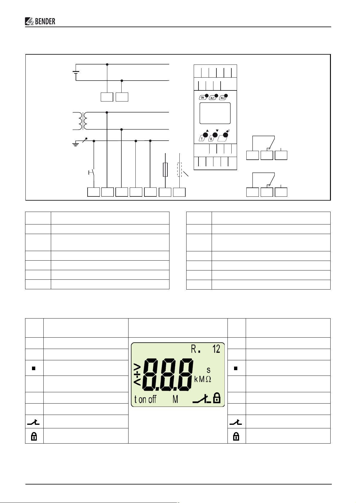
Anschlussplan
TEST
RESET
Klemme Anschlüsse
Wiring diagram
U
n
L1
L2
U
n
T/R
L1
L2
KE E
L+
L-
L1
L2
PE
U
6A 6A
E
L1
~/~/+
S
T/R
IT-System
A2A1
Terminal Connection
21
KE
11
L2
MENU
22
A1
12
A2
K1
14
141211
24
K2
242221
E, KE Separater Anschluss von E und KE an PE
A1, A2 Versorgungsspannung U
(siehe Typenschild) über
S
E, KE Connect the leads E and KE separately to PE.
A1, A2 Supply voltage US (see nameplate) via 6 A fuse
Schmelzsicherung 6 A
11, 12, 14 Alarm-Relais K1
21, 22, 23 Alarm-Relais K2 (Systemfehler-Relais)
T/R für Kombinierte, externe Test/Reset-Taste
L1, L2 Anschluss an das zu überwachende IT-System
Anzeige- und Bedienelemente
Element
R1, R2
Funktion
Ansprechwerte R
an1
, R
an2
Genutzte Elemente des Displays/
Display segments in use
11, 12, 14 Alarm relay K1
21, 22, 23 Alarm relay K2 (system fault relay)
T/R for combined external test/reset button
L1, L2 Connection to the system being monitored.
Indicating and operating elements
Element
R1, R2
Response values R
Function
an1
, R
1, 2 Alarm-Relais K1, K2 1, 2 Alarm relay K1, K2
Blinkender Punkt:
Messpuls des IR425
Anlaufverzögerung t,
t, t
on
Ansprechverzögerung t
on
Flashing dot:
Measuring pulse of the IR425
Starting delay t,
t, t
on
Response delay t
on
off Passwort-Schutz abgeschaltet off Password protection disabled
an2
M Fehlerspeicher aktiv M Fault memory activated
Betriebsart der Relais K1, K2 Operating mode of the relays K1, K2
Passwort-Schutz aktiv Password protection enabled
TBP103005 / 09.2010
3
Page 4

A-ISOMETER® IR425
Element
ON Betriebs-LED, grün ON Power ON LED, green
LED Alarm 1 leuchtet( gelb):
AL1,
Ansprechwert 1 unterschritten
AL2
LED Alarm 2 leuchtet (gelb):
Ansprechwert 2 unterschritten
>1 MΩ
MENU,
Display im Standard-Betrieb:
Isolationswiderstand R
Test-Taste: Starten eines Selbsttests
T,
(> 1,5 s);
Aufwärts-Taste: Menüpunkte/Werte
Reset-Taste: Löschen des Fehlerspei-
R,
chers (> 1,5 s);
Abwärts-Taste: Menüpunkte/Werte
Start des Menübetriebs (> 1,5 s) ;
Enter-Taste:
(< 1,5 s) Menü-, Untermenü-Punkt,
Wert bestätigen. (> 1,5 s) zurück zur
nächst höheren Menü-Ebene.
Funktion
> 1 MΩ
F
Werkseinstellung / Preset-Funktion
Bei erster Inbetriebnahme stellen sich in Abhängigkeit
automatisch folgende Ansprechwerte ein:
von U
n
> 72 V: Ansprechwert 1/2 (Alarm 1/2) = 46 kΩ / 23 k
U
n
Un ≤ 72 V: Ansprechwert 1/2 (Alarm 1/2) = 20 kΩ / 10 k
Gerätefront/
Front of the device
ON AL1 AL2
T
MENU
R
Factory setting / Preset function
Ω
Ω
Element
LED Alarm 1 lights ( yellow):
AL1,
value below response value 1
AL2
LED Alarm 2 lights (yellow):
value below response value 2
>1 MΩ
MENU,
During the first start-up process the following response
values are automatically set corresponding to Un:
> 72 V: response value 1/2 (Alarm 1/2) = 46 kΩ / 23 k
U
n
Un ≤ 72 V: response value 1/2 (Alarm 1/2) = 20 kΩ / 10 k
Display in standard mode:
insulation resistance RF > 1 MΩ
Test button: Starting a self test
T,
(> 1.5 s);
Up key: menu items/values
Reset button: deleting the fault
R,
memory (> 1.5 s);
Down key: menu items/values
Starting the menu mode (> 1,5 s) ;
Enter button:
(< 1,5 s) MENU, Sub menu item, confirm value. (> 1,5 s) back to the next
higher menu level.
Function
Ω
Ω
Arbeitsweise K1/K2: Arbeitsstrom-Betrieb N/O (n.o.)
Fehlerspeicher: deaktiviert
Anlaufverzögerung: t = 0 s
Ansprechverzögerung: t
Passwort: 1, deaktiviert
Menü-Übersicht
Menü-
punkt
AL
out
t
SEt
InF
ESC
Einstellbare Parameter
Ansprechwerte R
abfragen und einstellen
Fehlerspeicher ein- oder ausschalten,
Arbeitsstrom- oder RuhestromBetrieb für K1/K2 auswählen
Anlaufverzögerung t einstellen;
Ansprechverzögerung t
einstellen
Passwortschutz ein- oder ausschalten, Passwort ändern;
Werkseinstellung wiederherstellen;
Servicemenü SyS gesperrt
Hard- und Software-Version
abfragen
Zur nächst höheren Menüebene
bewegen (Zurück)
an1/Ran2
Operating mode K1/K2: N/O operation (n.o.)
Fault memory: deactivated
Starting delay: t = 0 s
on
= 0 s
Response delay: t
Password: 1, disabled
on
= 0 s
Menu overview
Menü-Struktur/
Menu structure
t > 1,5 s
t >1,5 s
AL
on
out
t
SEt
t < 1,5 s
InF
ESC
t < 1,5 s
t > 1,5 s
ESC
Menu
item
Response values R
AL
requesting and setting
Fault memory
out
activate or deactivate,
Select N/O or N/C operation
for K1/K2
t
Setting the starting delay t and
response delay ton
Enabling or disabling password pro-
SEt
tection, changing the password;
Reestablish the factory settings,
service menu SyS blocked
Calling up hardware and software
InF
versions
Move to the next higher
ESC
menu level
Parameter setting
an1/Ran2
4
TBP103005 / 09.2010
Page 5

A-ISOMETER® IR425
Einstellen der Parameter
Beispielhaft wird die Änderung des Alarm-Ansprechwerts R
(R 2) beschrieben. So gehen Sie vor:
1. Drücken Sie die Taste MENU/Enter länger als 1,5 s. Im Display erscheint das blinkende Kürzel AL.
2. Bestätigen Sie mit Enter. Der Parameter R1 blinkt.
3. Drücken Sie die Abwärts-Taste, um den Parameter R 2 auszuwählen. Der Parameter R 2 blinkt.
4. Bestätigen Sie die Auswahl mit Enter. Der zugehörige Wert
in kΩ blinkt.
5. Stellen Sie mit der Aufwärts- oder Abwärtstaste den
gewünschten Ansprechwert ein. Bestätigen Sie mit Enter.
R 2 blinkt.
6. Um das Menü zu verlassen, können Sie wahlweise durch:
– Drücken der Enter-Taste länger als 1,5 s je eine Ebene
höher gelangen
– oder Anwahl des Menüpunkts ESC und Bestätigung mit
Enter je eine Ebene höher gelangen.
Die jeweils einstellbaren Bereiche des Displays blinken!
Dargestellt wird dies durch eine ovale Markierung in den
folgenden Abbildungen.
Der Einstieg in den Menübetrieb erfolgt durch Drücken
der Taste MENU länger als 1,5 s.
an2
Parameter settings
An example is given below on how to change the alarm response
value R
1. Press the MENU/Enter button for more than 1.5 seconds.
2. Confirm with Enter. The parameter R1 flashes.
3. Press the Down key to select the parameter R2. The param-
4. Confirm with Enter.
5. Use the Up or Down key to set the appropriate response
6. You can exit the menu by:
(R 2). Proceed as follows:
an2
The flashing short symbol AL appears on the display.
eter R 2 flashes.
The associated value in kΩ flashes.
value. Confirm with Enter. R 2 flashes.
– pressing the Enter key for more than 1.5 seconds to
reach the next higher level
– or selecting the menu item ESC and confirming with
Enter to reach the next higher level.
The currently active segments are flashing! In the figures
below, the segments where device settings can be carried out are highlighted by an oval.
The menu mode can be reached by pressing the MENU
button for at least 1.5 seconds.
Ansprechwerte R
Mit diesen Einstellungen legen Sie fest, ab welchen Isolationswert-Unterschreitungen Vorwarnungen bzw. Alarme signalisiert
werden.
an1
/ R
einstellen
an2
Fehlerspeicher und Alarm-Relais einstellen
Hiermit können Sie den Fehlerspeicher M aktivieren oder deaktivieren. Außerdem können Sie die Arbeitsweise der Alarmrelais
K1 (1) und K2 (2) ändern:
Arbeitsstrom-Betrieb (n.o.) oder Ruhestrom-Betrieb (n.c.)
Response value R
Set the response value below which prewarnings and alarms are
to be signalled.
an1
/ R
an2
setting
Setting the fault memory and alarm relays
Use this segment to enter the settings for the fault memory M. In
addition, the operating principle of the alarm relays
K1 (1) and K2 (2) can be selected:
N/O operation (n.o.) or N/C operation (n.c.)
TBP103005 / 09.2010
5
Page 6

A-ISOMETER® IR425
Verzögerungszeiten einstellen
Hiermit können Sie eine Ansprechverzögerung ton (0...99 s) sowie
eine Anlaufverzögerung t (0...10 s) vorgeben
Werkseinstellung herstellen und Passwort-Schutz
Mit Hilfe dieses Menüs können Sie den Passwort-Schutz einschalten, das Passwort ändern oder den Passwort-Schutz abschalten.
Außerdem können Sie das Gerät auf die Werkseinstellungen zurücksetzen.
a) Passwort aktivieren
b) Passwort ändern
Setting the time delay
Use this segment to enter the response delay ton (0...99 s) and the
starting delay t (0...10 s).
Reset to factory setting and password protection
Use this menu to activate the password protection, to change the
password or to deactivate the password protection. In addition,
you can reset the device to its factory settings.
a) Activating the password
b) Changing the password
c) Passwort deaktivieren
Werkseinstellung wiederherstellen
Abfrage von Geräteinformationen
Hiermit fragen Sie die Version der Software (1.xx) ab. Die Daten
werden nach Start dieser Funktion als Laufband eingeblendet.
Nach Durchlauf der Routine können Sie mit den Aufwärts-/Abwärts-Tasten einzelne Datenabschnitte auswählen.
.... ....
Inbetriebnahme
Vor der Inbetriebnahme ist eine Kontrolle des ordnungsgemäßen
Anschlusses des A-ISOMETER®s erforderlich.
c) Deactivating the password
To reset to factory settings
....
How to call up device information
Use this function to query the software version (1.xx). After activating this function, data will be displayed as a scrolling text.
Once one pass is completed you can select individual data sections using the UP/DOWN keys.
Commissioning
Prior to commissioning, check proper connection
of the A-ISOMETER®.
Führen Sie eine Funktionsprüfung mittels eines echten Isolationsfehlers RF gegen Erde durch, ggf. über
einen dafür geeigneten Widerstand.
6
It is recommended to carry out a functional test using
a genuine earth fault, e.g. via a suitable resistance!
TBP103005 / 09.2010
Page 7

A-ISOMETER® IR425
Technische Daten IR425-D4..
Isolationskoordination nach IEC 60664-1/IEC 60664-3
Bemessungsspannung ........................................................................................................... 250 V
Bemessungs-Stoßspannung / Verschmutzungsgrad .................................................... 2,5 kV / III
Sichere Trennung (verstärkte Isolierung) zwischen:
............................................................... (A1, A2) - (L1, L2, E, KE, T/R) - (11-12-14) - (21-22-24)
Spannungsprüfung nach IEC 61010-1 ................................................................................. 2,21 kV
Versorgungsspannung
IR425-D4-1:
Versorgungsspannung U
Frequenzbereich Us ................................................................................................ 15...460 Hz / DC
IR425-D4-2:
Versorgungsspannung U
Frequenzbereich Us .................................................................................................. 15...460 Hz, DC
Eigenverbrauch .....................................................................................................................
Überwachtes IT-System
Netznennspannung U
Nennfrequenz f
Ansprechwerte
Ansprechwert R
Ansprechwert R
Preset-Funktion:
Un ≤ 72 V: R
Un > 72 V: R
an1
an1
Ansprechabweichung (1...5 kΩ) / (5...200 kΩ) ............................................. ±0,5 k
Hysterese (1...5 kΩ) / (5...200 kΩ) .................................................................. +1 k
.................................................................... AC 16...72 V / DC 9,6...94 V
s
..................................................................................... AC/DC 70...300 V
s
≤ 3 VA
........................................................................................ AC / DC 0... 300 V
n
............................................................................................................. 15...460 Hz
n
(ALARM 1) ...................................................................................... 1...200 k
an1
(ALARM 2) ...................................................................................... 1...200 k
an2
(ALARM 1)/ R
(ALARM 1)/ R
(ALARM 2) ........................................................ 20 kΩ / 10 k
an2
(ALARM 2) ........................................................ 46 kΩ / 23 k
an2
Ω /
Ω /
±15 %
+25 %
Technical data IR425-D4..
Insulation coordination acc. to IEC 60664-1/IEC 60664-3
Rated insulation voltage........................................................................................................... 250 V
Rated impulse voltage / Pollution degree ........................................................................ 2.5 kV / III
Protective separation (reinforced insulation) between:
.............................................................. (A1, A2) - (L1, L2, E, KE, T/R) - (11, 12, 14) - (21, 22, 24)
Voltage test acc. IEC 61010-1 .............................................................................................. 2.21 kV
Supply voltage
IR425-D4-1:
Supply voltage U
Frequency range Us ................................................................................................ 15...460 Hz / DC
IR425-D4-2:
Supply voltage U
Frequency range Us ................................................................................................. 15...460 Hz, DC
Power consumption .............................................................................................................. ≤ 3 VA
IT System being monitored
Nominal system voltage U
Nominal frequency f
Response values
Ω
Ω
Response value R
Response value R
Preset function:
Ω
Ω
Un ≤ 72 V: R
Un > 72 V: R
Operating error (1...5 kΩ) / (5...200 kΩ) ........................................... ±0.5 k
Hysteresis (1...5 kΩ) / (5...200 kΩ) .................................................................... +1 k
................................................................................ AC 16...72 V / DC 9.6...94 V
s
................................................................................................. AC/DC 70...300 V
s
..................................................... ............................ AC / DC 0... 300 V
n
..................................................................................................... 15...460 Hz
n
(ALARM 1).............................................................................. 1 kΩ...200 k
an1
(ALARM 2).............................................................................. 1 kΩ...200 k
an1
(ALARM 1)/ R
an1
(ALARM 1)/ R
an1
(ALARM 2) ........................................................ 20 kΩ / 10 k
an2
(ALARM 2) ........................................................ 46 kΩ / 23 k
an2
Ω /
Ω /
Ω
Ω
Ω
Ω
±15 %
+25 %
Zeitverhalten
Ansprechzeit t
bei RF = 0,5 x Ran und Ce = 1 μF. ................................................. .............. ≤ 2 s
an
Anlaufverzögerung t ............................................................................................................. 0...10 s
Ansprechverzögerung t
...... ............................................................................................... 0...99 s
on
Messkreis
Messspannung U
.......................... ................................................. ....................................... ±12 V
m
Messstrom Im (bei RF = 0Ω)............. .................................................. ........................... ≤ 200 μA
Innenwiderstand DC Ri........................ .................................................. ............................. ≥ 62 k
Impedanz Zi bei 50 Hz ..................................................................................... ................... ≥ 60 k
Zulässige Fremdgleichspannung Ufg.......................... ................................................. .. ≤ DC 300 V
Zulässige Netzableitkapazität C
........................ .................................................. ................ ≤ 20 µF
e
Anzeigen, Speicher
Anzeige ......................................................................... LC-Display, multifunktional, unbeleuchtet
Anzeigebereich Messwert .......................................................................................... 1 k
Ω
...1 M
Betriebsmessabweichung (1...5 kΩ) .............................................................................. ±0,5 k
Betriebsmessabweichung (5 kΩ...1 MΩ) .......................................................................... ±15 %
Passwort ......................................................................................................................... off / 0...999
Fehlerspeicher (Alarmrelais) ................................................................................................ on / off
Eingänge
Leitungslänge externe Test- / Reset-Taste .........................................................................
≤ 10 m
Schaltglieder
Anzahl .............................................................................................................. 2 (Wechsler K1, K2)
Arbeitsweise ................... ........................................................................ Ruhestrom / Arbeitsstrom
Elektrische Lebensdauer bei Bemessungsbedingungen ................................... 10 000 Schaltspiele
Kontaktdaten nach IEC 60947-5-1:
Bemessungsbetriebsspannung AC ....................................................................... 230 V....... 230 V
Gebrauchskategorie AC ........................................................................................ AC 13....... AC 14
Bemessungsbetriebsstrom AC ................................................................................. 5 A............ 3 A
Bemessungsbetriebsspannung DC ................................................... 220 V ....... 110 V.......... 24 V
Gebrauchskategorie DC ..................................................................... DC 12 ....... DC 12....... DC 12
Bemessungsbetriebsstrom DC ........................................................... 0,1 A ........ 0,2 A............ 1 A
Mindeststrom .............................................................................................. 1 mA bei AC/DC ≥ 10 V
Time response
Response time t
at RF = 0,5 x Ran and Ce = 1 μF ............................................ ................... ≤ 2 s
an
Starting delay t ................ .................................................... .................................................. 0...10 s
Response delay t
................................................................................................................ 0...99 s
on
Measuring circuit
Measuring voltage U
......................... .................................................. .................................. ±12 V
m
Measuring current Im (RF = 0Ω) .................................................................................. ≤ 200 μA
Ω
Ω
Internal d.c. resistance Ri.......................... ................................................. ......................... ≥ 62 k
Internal impedance Zi (50 Hz) ........................................................................................... ≥ 60 k
Ω
Ω
Admissible extraneous d.c. voltage Ufg........................ ................................................. ≤ DC 300 V
System leakage capacitance C
........................ .................................................. .................. ≤ 20 µF
e
Displays, memory
Display.................................................. .................... LC display, multi-functional, non-illuminated
Ω
Ω
Display range, measuring value ................................................................................ 1 k
Ω
...1 M
Operating error (1...5 kΩ) ................................................................................................ ±0.5 k
Ω
Ω
Percentage operating error (5 kΩ...1 MΩ) ........................................................................ ±15 %
Password ........................................................................................................................ off / 0...999
Fault memory (alarm relay) .................................................................................... ............. on / off
Inputs
Cable length external test / reset button ..............................................................................
≤ 10 m
Switching elements
Number of....................................................................................... 2 (changeover contacts K1, K2)
Operating principle........................................................................ (N/O operation)(N/C operation)
Electrical endurance ............................................................................ 10 000 switching operations
Contact data according IEC 60947-5-1
Rated operational voltage AC ............................................................................... 230 V ....... 230 V
Utilization category AC ........................................................................................ AC 13 ....... AC 14
Rated operational current AC .................................................................................. 5 A ........... 3 A
Rated operational voltage DC ............................................................ 220 V....... 110 V ......... 24 V
Utilization category DC ................................... ................................... DC 12 ........DC 12 ....... DC 12
Rated operational current DC ............................................................ 0.1 A ........ 0.2 A ........... 1 A
Minimum current .............................................................. ............................ 1 mA at AC/DC ≥ 10 V
TBP103005 / 09.2010
7
Page 8

A-ISOMETER® IR425
Umwelt/EMV
EMV ....................................................................... .................................................. .. nach IEC 61326
Arbeitstemperatur .................................................................................................. -25 ºC...+55 ºC
Klimaklassen nach IEC 60721:
Ortsfester Einsatz (IEC 60721-3-3) (ohne Betauung und Eisbildung)....................................... 3K5
Transport (IEC 60721-3-2) (ohne Betauung und Eisbildung) ................................................... 2K3
Langzeitlagerung (IEC 60721-3-1) (ohne Betauung und Eisbildung) ...................................... 1K4
Mechanische Beanspruchung nach IEC 60721:
Ortsfester Einsatz (IEC 60721-3-3) .......................................................................................... 3M4
Transport (IEC 60721-3-2) ...... ................................................................................................. 2M2
Langzeitlagerung (IEC 60721-3-1) .......................................................................................... 1M3
Anschluss ........................ ................................................. ................................ Schraubklemmen
Anschlussvermögen:
starr / flexibel / Leitergrößen AWG....................................... 0,2...4 / 0,2...2,5 mm
Mehrleiteranschluss (2 Leiter gleichen Querschnitts):
starr / flexibel ............................................................................................ 0,2...1,5 / 0,2.. .1,5 mm
Abisolierlänge ................................................................ ................................................. ......... 8 mm
Anzugsdrehmoment .................................................................................................... 0,5...0,6 Nm
Anschluss ........................ ................................................. ..................................... Federklemmen
Anschlussvermögen:
starr .................................................................................................. 0,2...2,5 mm2 ( AWG 24...14)
flexibel ohne Aderendhülse ............................... ............................... 0,2...2,5 mm2 (AWG 24...14)
flexibel mit Aderendhülse ................... ............................................. 0,2...1,5 mm2 ( AWG 24...16)
Abisolierlänge ................................................................ ................................................. ....... 10 mm
Öffnungskraft ............................................................................................................................ 50 N
Testöffnung, Durchmesser ................................................................................................... 2,1 mm
Sonstiges
Betriebsart. .............................................................................. ...................................... Dauerbetrieb
Einbaulage ............................................................................................................................ beliebig
Schutzart, Einbauten (DIN EN 60529) ....................................................................................... IP30
Schutzart, Klemmen (DIN EN 60529) ........................................................................................ IP20
Gehäusematerial ........................................................................................................... Polycarbonat
Entflammbarkeitsklasse..................................................................................................... UL94 V-0
Schnellbefestigung auf Hutprofilschiene ......................................................................... IEC 60715
Schraubbefestigung ................................................................................... 2 x M4 mit Montageclip
Gewicht .............................................................................................................................. ca. 150 g
2
/AWG 24...12
Environment/EMC
EMC ....................................................................................................................... acc. to IEC 61326
Operating temperature ........................................................................................... -25 °C...+55 °C
Climatic categories acc. to IEC 60721:
Stationary use (IEC 60721-3-3) (except condensation and formation of ice) ......................... 3K5
Transport (IEC 60721-3-2) (except condensation and formation of ice) ................................. 2K3
Storage (IEC 60721-3-1) (except condensation and formation of ice) .................................... 1K4
Classification of mechanical conditions acc. to IEC 60721:
Stationary use (IEC 60721-3-3) .................................................................................................3M4
Transport (IEC 60721-3-2) .........................................................................................................2M2
Storage (IEC 60721-3-1) ............................................................................................................1M3
Connection........................................................................................... ................ screw terminals
Connection properties:
rigid / flexible / AWG ............................................................ 0.2...4 / 0.2...2.5 mm
2
Two conductors with the same cross section:
rigid / flexible............................................................................................. 0. 2...1.5 / 0.2...1.5 mm
Stripping length ...................................................................................................................... 8 mm
Tightening torque, terminal screws ............................................................................. 0.5...0.6 Nm
Connection........................................................................................... ....... push-wire terminals
Connection properties:
rigid .................................................................................................. 0.2...2.5 mm2 ( AWG 24...14)
flexible without ferrules ................ ................................................... 0.2...2.5 mm2 ( AWG 24...14)
flexible with ferrules ......................................................................... 0.2...1.5 mm2 ( AWG 24...16)
Stripping length .................................................................................................................... 10 mm
Opening force ............................................................................................................................. 50 N
Test opening, diameter ........................................................................................................ 2.1 mm
Other details
Operating mode .............................................................................................................. continuous
Position ................................................................................................................. ......... any position
Degree of protection internal components (EN 60529) ........................................................... IP30
Degree of protection terminals (EN 60529) .............................................................................. IP20
Enclosure material ....................................................................................................... polycarbonat
Flammability class .............................................................................................................. UL94 V-0
DIN rail mounting acc. to.................................... .................................................... ........... IEC 60715
Screw fixing ............................................................................................ 2 x M4 with mounting clip
Weight ......................................................................................................................... approx. 150 g
2
/AWG 24...12
2
Bestellangaben (B 7... = Federklemmen)
Typ Versorgungsspg. U
IR425-D4-1 DC 9,6...94 V / AC 16...72 V, 15...460 Hz B 7103 6403
IR425-D4-2 DC 70...300 V / AC 70...300 V, 15...460 Hz B 7103 6402
*Absolutwerte des Spannungsbereichs
Montageclip für Schraubmontage (1 Stück je Gerät, Zubehör) B 9806 0008
* Art.-Nr.
s
B 9103 6403
B 9103 6402
Alle Rechte vorbehalten.
Nachdruck und Vervielfältigung
nur mit Genehmigung des Herausgebers.
Änderungen vorbehalten!
© Dipl.-Ing. W. Bender GmbH & Co. KG
Ordering details (B 7... = push-wire terminals)
Type Supply voltage U
IR425-D4-1 DC 9,6...94 V / AC 16...72 V, 15...460 Hz B 7103 6403
IR425-D4-2 DC 70...300 V / AC 70...300 V, 15...460 Hz B 7103 6402
*absolute value of the voltage range
Mounting clip for screw fixing (1 piece per device, accessories) B 9806 0008
* Art. No.
s
B 9103 6403
B 9103 6402
All rights reserved.
Reprinting and duplicating
only with permission of the publisher.
Subject to change!
© Dipl.-Ing. W. Bender GmbH & Co. KG
Dipl.-Ing. W. Bender GmbH & Co. KG Tel.: +49 6401 807-0 E-Mail: info@bender-de.com
Londorfer Str. 65
Postfach 1161
• 35305 Grünberg • Germany Fax: +49 6401 807-259 Web: http://www.bender-de.com
• 35301 Grünberg • Germany
8
TBP103005 / 09.2010
 Loading...