

Page 1

EDS150
Isolationsfehlersuchgerät
Deutsch English
Bestimmungsgemäße Verwendung
Das Isolationsfehlersuchgerät EDS150 wird zur Lokalisierung von
Isolationsfehlern in AC-, AC/DC- sowie DC-IT-Systemen eingesetzt. Den für die Isolationsfehlersuche erforderlichen Prüfstrom
liefert ein ISOMETER
PGH471.
® IRDH575 oder ein Prüfstromgenerator
Sicherheitshinweise allgemein
Bestandteil der Gerätedokumentation sind neben diesem Beipackzettel die beiliegenden „Wichtigen sicherheitstechnischen
Hinweise für Bender-Produkte“.
Sicherheitshinweise gerätespezifisch
BMS-Adressen dürfen nicht doppelt vergeben werden. Andernfalls kann es zu Störungen im BMS-Bus
kommen.
Gerätemerkmale
● Isolationsfehlersuche in AC-, AC/DC- und DC-IT-Systemen
● 6 Messkanäle mit Messstromwandler je EDS150
● Bis zu 528 Messkanäle im überwachten IT-System mittels
BMS-Bus kombinierbar: 88 x 6 Messkanäle
● Ansprechempfindlichkeit 5 mA
● Maximal 8 s Ansprechzeit im AC-Netz gemäß IEC 61557-9
● RS-485-Schnittstelle mit BMS-Protokoll
● BMS-Adressbereich 3...90
● Zyklischer Selbsttest
Funktionsbeschreibung
Gestartet wird die Isolationsfehlersuche von einem ISOMETER®
IRDH575 oder einem Prüfstromgenerator PGH471. Nach dem
Start beginnt das Isolationsfehlersuchgerät EDS150 mit der Messung über alle Messstromwandler-Kanäle 1...6. Wird in einem Kanal der Ansprechwert von 5 mA überschritten, leuchtet die
zugehörige Alarm-LED auf. Der anstehende Alarm wird mit
Adress- und Kanal-Angabe über die BMS-Schnittstelle ausgegeben. Der fehlerbehaftete Abgang wird entweder von einer Meldekombination oder einem BMS-Master mit Display angezeigt.
Siehe auch „Empfohlene Gerätekombinationen“ auf Seite 8.
Sind mehrere EDS150 vorhanden, werden diese ebenfalls alle
gleichzeitig gestartet. Ein Fehler, der z. B. von Kanal 1 ausgegeben wird, ist durch seine BMS-Adresse eindeutig einem der
überwachenden EDS150 zugeordnet.
Stündlich läuft ein automatischer Selbsttest ab, der die Funktion
aller Messstromwandler überwacht. Bei einem Gerätefehler blinken alle Alarm-LEDs K1...K6.
Eine Alarmmeldung bleibt so lange erhalten, bis das EDS150 am
überwachten Kanal keinen Isolationsfehler mehr erfasst oder
das Isolationsüberwachungsgerät den Wegfall des Isolationsfehlers über den BMS-Bus signalisiert.
Treten in den Messstromwandlern Differenzströme > 10 A auf,
wird die Isolationsfehlersuche für den jeweiligen Kanal abgebrochen und über den BMS-Bus die Alarmmeldung Differenzstromfehler > 10 A ausgegeben (RCM-Funktion). Nur während der
Isolationsfehlersuche ist die RCM-Funktion aktiv.
Insulation fault locator
Intended use
The EDS150 insulation fault locator is designed to localise insulation faults in AC, AC/DC and DC IT systems. The locating current
required for insulation fault location is provided by the
ISOMETER
Safety instructions
In addition to these operating instructions, the "Important safety
instructions for Bender products“, which are also included in the
scope of supply, are an integral part of the device documentation.
Device-specific safety information
Device features
● Insulation fault location in AC, AC/DC and DC-IT systems
● 6 measuring channels with measuring current transformer
● Up to 528 measuring channels can be combined by the
● Response sensitivity 0.5 mA
● A response time of up to 8 s in the AC system according to
● RS-485 interface with BMS protocol
● BMS address range 3...90
● Cyclical self test
Function
Insulation fault location is started by the ISOMETER® IRDH575 or
the locating current injector PGH471. Once started, the insulation
fault locator EDS150 starts scanning all measuring channels 1...6.
When the response value of 5 mA is exceeded in one of the channels, the associated alarm LED lights up. The current alarm message and the respective address and channel number will be
output via the BMS interface. The faulty circuit will be shown on
either an alarm and test combination or a BMS master featuring a
display.
Also refer to "Recommended device combinations" on page 8.
If there is more than one EDS150, all devices will be started simultaneously. An error outputted by channel 1, for example, can be
clearly assigned to the respective EDS150 by its BMS address.
An automatic self test monitoring the function of all measuring
current transformers is carried out on an hourly basis. When a
device error occurs, all alarm LEDs K1...K6 flash.
The alarm status remains activated until the EDS150 no longer
detects an insulation fault or the insulation monitoring device
signals via the BMS bus that the insulation fault is eliminated.
If residual currents > 10 A occur on the measuring current transformers, insulation fault location on the respective channel will
be terminated and the alarm message "residual current fault
> 10 A" will be outputted via the BMS bus (RCM function).
® IRDH575 or the locating current injector PGH471.
Please do not assign BMS addresses more than once.
Otherwise, it may result in malfunctioning or cause
problems in the BMS bus environment.
per EDS150
BMS bus in the IT system being monitored: 88 x 6 measuring channels
IEC 61557-9
TBP108026deen / 08.2012
1
Page 2
EDS150
Montage, Anschluss und Inbetriebnahme
Für UL-Anwendungen:
Nur 60°C/75°C-Kupferleitungen verwenden!
Maximale Umgebungstemperatur = 55°C
Sorgen Sie für Spannungsfreiheit im Montagebereich
und beachten Sie die Regeln für das Arbeiten an elektrischen Anlagen.
1. Prüfen Sie, ob die werksseitig eingestellte BMS-Adresse 3
bereits an einen anderen Bus-Teilnehmer vergeben wurde
(z.B bei mehreren zu installierenden EDS150).
Stellen Sie gegebenenfalls eine noch nicht vergebene
Adresse ein. Vermeiden Sie Adresslücken!
2. Montieren Sie das EDS150 mit 2 x M6-Schrauben beispielsweise auf einer Lochschiene.
3. Verdrahten Sie das Gerät gemäß Anschlussplan.
Beachten Sie bitte, dass die Versorgungsspannung für das
EDS150 AC/DC 24V beträgt!
4. Vor der Inbetriebnahme ist eine Kontrolle des ordnungsgemäßen Anschlusses des EDS150 erforderlich.
Führen Sie im Rahmen der Inbetriebnahme einen Funktionstest mittels eines echten Isolationsfehlers durch, ggf.
über einen dafür geeigneten Widerstand!
The RCM function is active only during the insulation fault
location process.
Installation, connection and commissioning
For UL applications:
Use 60°C/75°C copper conductors only!
Max. surrounding air temperature = 55°C
Ensure safe isolation from supply in the installation
area.
Observe the installation rules for live working.
1. Check that BMS address 3 set at the factory has already
been assigned to another bus device (e.g. when several
EDS150 are to be installed).
If required, set an address that has not been assigned yet.
Avoid address gaps!
2. Install the EDS150 using 2 x M6 screws on a perforated rail
for example.
3. Connect the device according the wiring diagram. Please
note that the supply voltage for EDS150 is AC/DC 24V!
4. Prior to commissioning ensure that the EDS150 is properly
connected.
During commissioning, carry out a functional test using a
genuine insulation fault, where appropriate via a suitable
resistance!
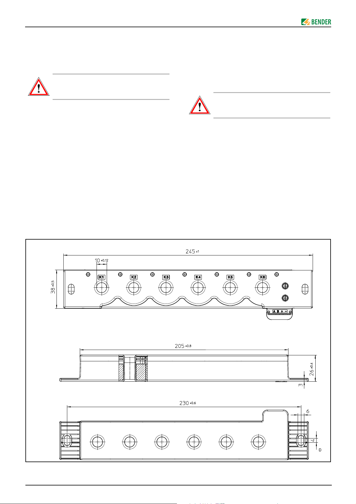
Maßbild
Dimension diagram
Alle Maßbild-Angaben in mm.
2
All dimensions are given in mm.
TBP108026deen / 08.2012
Page 3
EDS150
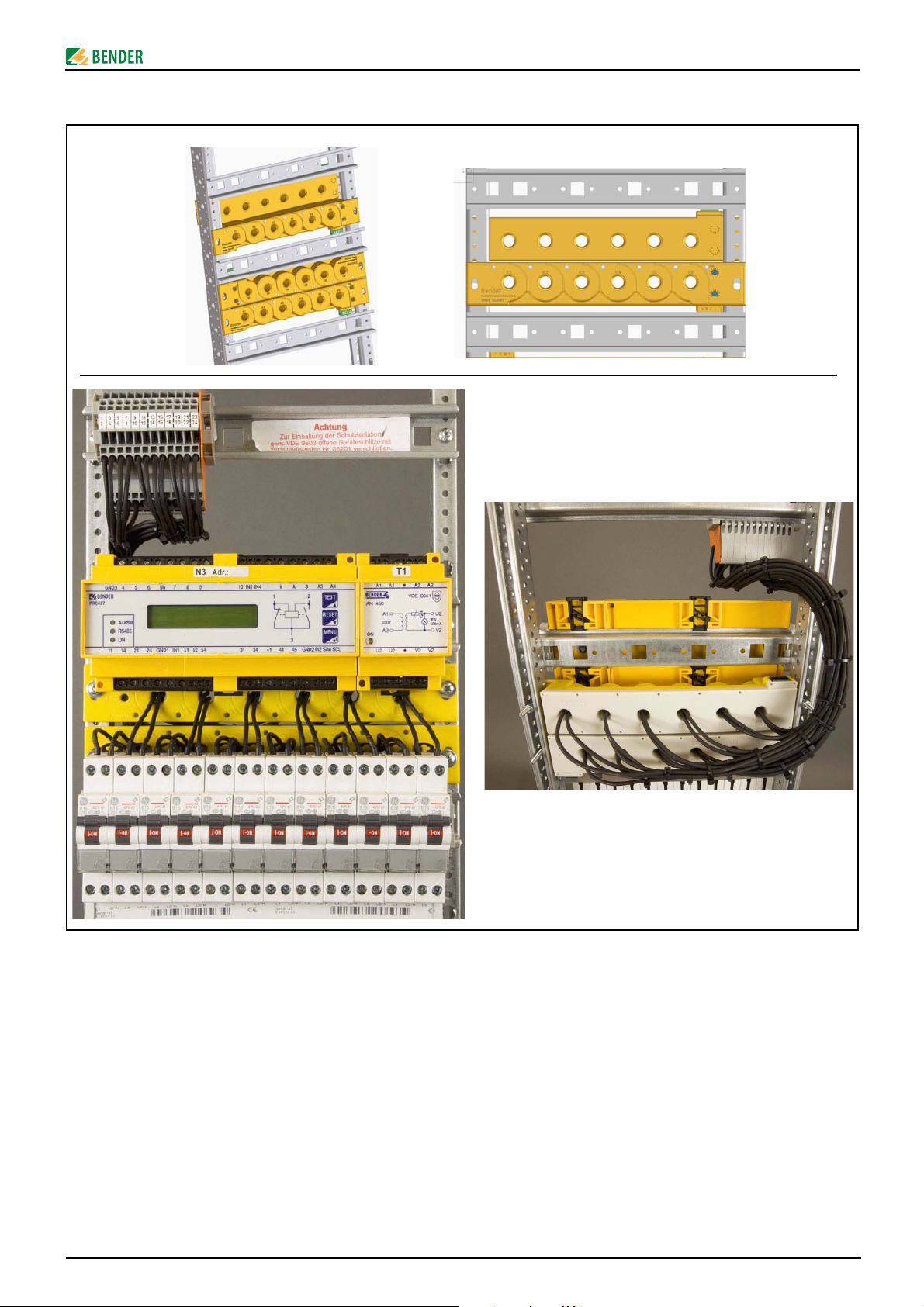
Montage- und Verdrahtungsbeispiele
Installation and wiring examples
Installationshinweise
● Alle stromführenden Leitungen eines Abgangs sind durch
den Messstromwandler zu führen!
Die Durchführung der Leitungspaare kann beliebig von
der Vorder- oder Rückseite erfolgen
● Ein Schutzleiter darf grundsätzlich nicht durch den Mess-
stromwandler geführt werden!
● Abgeschirmte Leitungen nicht durch den Messstrom-
wandler führen!
● Benachbarte magnetische Streufelder können die Emp-
findlichkeit der Messstromwandler beeinflussen. Deshalb
ist bei der Montage die Nähe von Transformatoren und
Drosseln zu meiden.
TBP108026deen / 08.2012
Installation instructions
● Make sure to route all live conductors of a circuit through
the measuring current transformer!
The conductor pairs can be passed through the CT‘s front
or rear side
● As a matter of principle, do not route a PE conductor
through the measuring current transformer!
● Do not route shielded cables through the measuring cur-
rent transformer!
● Adjacent magnetic stray fields may influence the measur-
ing current transformer. Therefore, it is recommended not
to install the device in the vicinity of transformers and
throttles.
3
Page 4

EDS150
A
A
A
A
A
A
K1 K2 K3 K4 K5 K6
ON/COM
0
1
2
3
4
5
6
7
8
9
0
1
2
3
4
5
6
7
8
9
123 45
6
A B +
7
8
x 1
x 10
Anschlussplan
L1
N
PE
EDS150
IT-SystemTN-System
L1'
L2'
F1 F2 F3
F4 F5
Wiring diagram
F6
F7
24V
DC
+
A
B
Bus-Terminierung
120 Ω, extern
Bus termination
120 Ω, external
230V
AC
MK2430/
MK800
A B A B+ -
U2 V2
Bus-Terminierung
120 Ω, interner Schalter
Bus termination
120 Ω, internal switch
E KE
IRDH575
F8
L2 L1A2 A1
bgang 1
Anzeige- und Bedienelemente, Schnittstelle
Element Funktion
1 Öffnung für Schraubbefestigung
2 Alarm-LEDs für die Messkanäle K1...K6
Leitungsdurchführung der Messstromwandler
3
für die Messkanäle K1...K6
ON/COM-LED:
4
Betriebs-LED und Busaktivität
5 Einer-Stelle der BMS-Adresse einstellen
6 Zehner-Stelle der BMS-Adresse einstellen
7 Anschluss Versorgungsspannung
8 Anschluss RS-485, BMS-Bus
circuit 1
bgang 2
circuit 2
bgang 3
circuit 3
bgang 4
circuit 4
bgang 5
circuit 5
bgang 6
circuit 6
Display and operating controls, interface
Element Function
1 Opening for screw mounting
2 Alarm LEDs for the measuring channels K1...K6
CT openings for passing through the electrical wires
3
for the measuring channels K1...K6
ON/COM LED:
4
Power On LED and bus activity EDS150
5 Set the ones position of the BMS address
6 Set the tens position of the BMS address
7 Connection to the power supply
8 Connection for the RS-485, BMS bus
4
TBP108026deen / 08.2012
Page 5

EDS150
0,00
0,10
0,20
0,30
0,40
0,50
0,60
0,70
0,80
0,90
1,00
0 5000 10000 15000 20000 25000
C
e
x
U
n
[μFV]
ACSystem: Un=0,6xU
n
AC
DCSystem: Un=1,0xU
n
DC
R
an
Ce=0μF
=Un/I
an
Ran=KxR
an
Ce=0μF
Ran=f(Ce,Un)
LED-Funktionen
LED
ON / COM
Leuchtet konstant
Lights permanently
Betrieb
Power on
Blinkt mit f < 1 Hz
Flashes with f < 1 Hz
Busaktivität
Bus activity
Systemfehler:
Alarm K1...K6
Alarm EDS oder RCM
Alarm EDS or RCM
LEDs K1...K6 blinken
System error:
LEDs K1...K6 flash
Legende:
* = Prüfstromtakt: 2s an, 4s aus
Markierte Tabellenzellen = Alarm bzw. Fehler
Ableitkapazität und Nennspannung beeinflussen das Ansprechverhalten des EDS150
Der resultierende Isolationswiderstands-Ansprechwert Ran wird
schrittweise mit Hilfe der Formeln und des Diagramms ermittelt.
1. Bewertung der Netzformen AC oder DC
AC-System: Un = 0,6 Un
DC-System: Un = 1,0 Un
2. Berechnen des normierten Ansprechwerts R
einer angenommenen Ableitkapazität von Ce = 0μF und
dem EDS-Ansprechwert I
R
an(Ce = 0μF)
= Un/I
3. Aus dem Diagramm den Korrekturfaktor K entnehmen,
durch Bilden des Produkts aus bewerteter Un und realer
Ableitkapazität Ce.
4. Realen Ansprechwert berechnen:
Ran = K x R
an(Ce = 0μF)
Beispiel für ein Netz mit AC 230 V:
zu 1) = 138 V zu 2) bei 5 mA = 27,6 kΩ
zu 3) bei 10 μF = 0,33 zu 4) = 9,1 kΩ
(AC)
(DC)
an(Ce = 0μF)
= 5 mA:
an
an
mit
LED functions
Blinkt im Prüfstromtakt *
Flashes with locating
current cycle *
–––
Leuchtet nicht
Doesn‘t light
keine Versorgungsspannung
No supply voltage
Anzeige des aktiven Mess-
kanals
Indication of the active
kein Alarm
No alarm
measuring channel
Legend:
* = locating current pulse: 2s on, 4 s off
Marked table cells = Alarm respectively error
The leakage capacitance and nominal voltage
influence the response characteristics of the EDS150
The response value Ran of the insulation resistance can be determined step-by-step using the formulas and the diagram below.
1. Evaluation of the type of system AC or DC
AC system: U
DC system: Un = 1.0 U
2. Calculation of the standardised response value R
assuming a leakage capacitance of Ce = 0 μF and the EDS
response value Ian = 5 mA:
R
an (Ce = 0 μF)
3. Selecting a correction factor K from the diagram by calculating the product of the evaluated Un and real leakage
capacitance C
4. Calculating the real response value:
R
= K x R
an
Example of a system with AC 230 V:
with respect to 1) = 138 V with respect to 2) at 5 mA = 27.6 kΩ
with respect to 3) at 10 μF = 0.33 with respect to 4) = 9.1 kΩ
= 0.6 U
n
= Un/I
an
.
e
an (Ce = 0 μF)
n (AC)
n (AC)
an (Ce=0 μF)
TBP108026deen / 08.2012
5
Page 6

EDS150
Störungen im überwachten Netz
Treten Störungen im überwachten Netz oder auf dem BMS-Bus
auf, kann es vorkommen, dass bereits gefundene Fehler in der
nächsten Messfolge nicht erneut gemessen werden können und
deshalb kein Alarm signalisiert wird. In der Regel wird ein weiter
bestehender Fehler nach der nächsten Messung wieder lokalisiert.
Alarmmeldungen je BMS-Kanal
EDS150 stellt für andere Busteilnehmer Alarmmeldungen bereit.
Diese können durch einen BMS-Master abgefragt werden.
Betriebsmeldungen werden nicht erzeugt.
BMS-
Kanal
1...6
Bedeutung
- Isolationsfehler mit Angabe des Fehlerstroms
in mA
- Differenzstromfehler > 10 A
- Störimpulse im überwachten System
7 Gerätefehler, intern
Technische Daten
Disturbances in the system being monitored
If disturbances occur in the system being monitored, it may happen that faults which have already been found will not be
measured again during the subsequent measurement and therefore an alarm will not be signalled. Usually, an existing fault will
be localised again during the subsequent measurement.
Alarm messages for BMS channels
EDS150 provides alarm messages for other bus devices. These
alarm messages can be queried by a BMS master.
Operational status messages are not generated.
BMS
channel
1...6
Meaning
- Insulation fault with value of the fault current
in mA
- Residual current fault > 10 A
- Disturbing pulses in the monitored system
7 Device fault, internal
Technical data
Isolationskoordination nach IEC 60664-1 / IEC 60664-3
Bemessungsspannung ....................................................................................................... AC 250 V
Bemessungs-Stoßspannung/Verschmutzungsgrad ........................................................... 6 kV / 3
Spannungsbereiche
Überwachtes IT-System:
Netznennspannung U
Nennfrequenz fn.............................................................................................................. 42...460 Hz
Versorgungsspannung:
Versorgungsspannung U
Frequenzbereich der Versorgungsspannung .................................................................. 50...60 Hz
Eigenverbrauch AC ................................................................................................................ ≤ 3 VA
Eigenverbrauch DC .............................................................................................................. ≤ 1,5 W
Messkreis
Anzahl Messkanäle (pro Gerät / pro System) ...................................................................... 6 / 528
EDS-Funktion:
Ansprechwert I
Prozentuale Ansprechunsicherheit ............................................................................. ........ ± 30 %
Bemessungsfrequenz .................................................................................................. 42…460 Hz
Messbereich EDS-Funktion ............................................................................................ 5…25 mA
Ansprechzeit im AC-Netz nach IEC 61557-9 .......................................................................... ≤ 8 s
Abfragezeit für alle Kanäle ......... .......................................................................................... ca. 72 s
RCM-Funktion:
Ansprechwert ............................................................................................................................ 10 A
Prozentuale Ansprechunsicherheit ............................................................................. ........ ± 30 %
Bemessungsfrequenz ..................................................................................................... 42…68 Hz
............................................................................... siehe IRDH575, PGH471
n
........................................................................ AC 17...24 V, DC 14...28 V
s
...................................................................................................................... 5 mA
an
Insulation coordination acc. to IEC 60664-1 / IEC 60664-3
Rated insulation voltage...................................................................................................... AC 250 V
Rated impulse voltage/pollution degree .............................................................................. 6 kV / 3
Voltage ranges
IT system being monitored:
Nominal system voltage U
Nominal frequency fn...................................................................................................... 42...460 Hz
Supply voltage:
Supply voltage U
Frequency range of the supply voltage ............................................................................ 50...60 Hz
Power consumption AC ........................................................................................................ ≤ 3 VA
Power consumption DC ...................................................................................................... ≤ 1.5 W
Measuring circuit
Number of measuring channels (per device/system) .......................................................... 6 / 528
EDS function:
Response value I
Relative uncertainty........................................................... ................................................ ....± 30 %
Rated frequency ...................................................... ................................................... ...42…460 Hz
Measuring range EDS function........................................................................................ 5…25 mA
Response time in the AC system according to IEC 61557-9 .................................................. ≤ 8 s
Scanning time for all channels....................................................................................... approx. 72 s
RCM function:
Response value ........................................................................................................................... 10 A
Relative uncertainty........................................................... ................................................ ....± 30 %
Frequency range .............................................................................................. .............. 42…68 Hz
.......................................................................... see IRDH575, PGH471
n
............................ ........................................................ AC 17...24 V, DC 14...28 V
s
..................................................................................................................... 5 mA
an
Anzeigen
LEDs:
ON / COM, grün ................................................................................ Betriebsanzeige / Busaktivität
ALARM K1...K6, gelb............................................................... ................... EDS- und RCM-Funktion
Schnittstelle
Schnittstelle / Protokoll ............................................................................................. RS-485 / BMS
Anschluss ................................................................................................................. Klemmen A / B
Schirmleitung (Schirm einseitig an PE) ......................................... zweiadrig, z.B.: J-Y(St)Y 2x0,8
Leitungslänge .................................................................................................................. ≤ 1200 m
Ω
Abschlusswiderstand.............. ................................................................................. 120
Geräteadresse, BMS-Bus .................................................................................................. 3...90 (3)*
(0,25 W)
6
Displays
LEDs:
ON / COM, green .......................................... ................................ operation indicator / bus activity
ALARM K1...K6, yellow.................................................................................. EDS and RCM function
Interface
Interface / protocol.. ................................................................................................... RS-485 / BMS
Connection..................................... .................................................... .......................... terminals A/B
Shielded cable (shield connected to PE on one side)..................... two-core, e.g.: J-Y(St)Y 2x0.8
Cable length................ ....................................................................................................... ≤ 1200 m
Ω
Terminating resistor ............................................................................................... 120
Device address, BMS bus................................................................................................. 3...90 ( 3)*
TBP108026deen / 08.2012
(0.25 W)
Page 7

EDS150
Umwelt / EMV
EMV ........................................................................................................................... IEC 61326-2-4
Arbeitstemperatur .................................................................................................... -25…+55 °C
Für UL-Anwendungen:
Maximale Umgebungstemperatur ............................................................................................ 55°C
Klimaklassen nach IEC 60721:
Ortsfester Einsatz (IEC 60721-3-3) ..................................... 3K5 (ohne Betauung und Eisbildung)
Transport (IEC 60721-3-2) .... .............................................. 2K3 (ohne Betauung und Eisbildung)
Langzeitlagerung (IEC 60721-3-1) .......................... ........... 1K4 (ohne Betauung und Eisbildung)
Mechanische Beanspruchung nach IEC 60721:
Ortsfester Einsatz (IEC 60721-3-3) .......................................................................................... 3M4
Transport (IEC 60721-3-2) ...... ................................................................................................. 2M2
Langzeitlagerung (IEC 60721-3-1) .......................................................................................... 1M3
Anschluss
Anschlussart................................................................................................ steckbare Federkle
mme
Für UL-Anwendungen:
Nur 60°C/75 °C-Kupferleitungen verwenden!
Anschlussvermögen:
starr, flexibel / Leitergrößen AWG .................................................... 0,2...1,5 mm
2
/ AWG 24...16
Mehrleiteranschluss (2 Leiter gleichen Querschnitts):
starr ............................................................................................................................ 0,2...1,5 mm
flexibel ........................................................................................................................ 0,2...1,5 mm
flexibel mit Aderendhülse ohne Kunststoffhülse..................................................... 0,25...1,5 mm
flexibel mit Aderendhülse mit Kunststoffhülse ..................................................... 0,25...0,75 mm
Abisolierlänge ....................................................................................................................... 10 mm
Sonstiges
Betriebsart .................................................................................................................... Dauerbetrieb
Gebrauchslage ..................................................................................................................... beliebig
Gehäusematerial ......................................................................................................... Polycarbonat
Schutzart, Einbauten (DIN EN 60529) ....................................................................................... IP30
Schutzart, Klemmen (DIN EN 60529) ....................................................................................... IP20
Entflammbarkeitsklasse ..................................................................................................... UL94V-0
Schraubbefestigung ............................................................................................................... 2 x M6
Anzugsdrehmoment ............................................................................................................. 1,5 Nm
Software-Version ........................................................................................................... D353 V1.0x
Gewicht ............................................................................................................................... ≤ 340 g
( )* = Werkseinstellung
Environment / EMC
EMC ............................................................................................................................ IEC 61326-2-4
Operating temperature .............................................................................................. -25…+55 °C
For UL application:
Max. surrounding air temperature ............................................................ ................................ 55°C
Classification of climatic conditions acc. to IEC 60721:
Stationary use (IEC 60721-3-3) ..........................3K5 (except condensation and formation of ice)
Transport (IEC 60721-3-2) .................................. 2K3 (except condensation and formation of ice)
Long-term storage (IEC 60721-3-1) ..................1K4 (except condensation and formation of ice)
Classification of mechanical conditions acc. to IEC 60721:
Stationary use (IEC 60721-3-3) ............................................................. ....................................3M4
Transport (IEC 60721-3-2) ........................................................................................................ 2M2
Storage (IEC 60721-3-1) ........................................................................................................... 1M3
Connection
Connection type................................................................................ pluggable push-wire terminal
For UL application:
Use 60 °C/75°C copper conductors only!
Connection properties:
rigid, flexible / conductor sizes AWG ................................................ 0.2...1.5 mm
2
2
2
2
Multi-conductor connection (2 conductors with the same cross section):
rigid............................................................................................................................. 0.2...1.5 mm
flexible ........................................................................................................................ 0.2...1.5 mm
flexible with ferrule without plastic sleeve ........................................................ .......0.25...1.5 mm
flexible with ferrule with plastic sleeve .................... .............................................. 0.25...0,75 mm
2
/ AWG 24...16
2
2
2
2
Stripping length...................................................................................................................... 10 mm
General data
Operating mode .............................................................................................. continuous operation
Position of normal use ................................................................................................................. any
Enclosure material.......................................................................................................polycarbona te
Degree of protection, internal components (DIN EN 60529) ................................................... IP30
Degree of protection, terminals (DIN EN 60529) ...................................................................... IP20
Flammability class ............................................................................................................... UL94V-0
Screw mounting ...................................................................................................................... 2 x M6
Tightening torque.................................................................................................................. 1.5 Nm
Software version ........................................................................................................ .... D353 V1.0x
Weight ................................................................................................................................. ≤ 340 g
( )* = factory setting
Bestellangaben
Typ e
EDS150
AN410
AN430 AC 85...264 V, 47...63Hz* DC 24 V, 1300 mA B 924 208
AN450 AC 230 V, 50...60 Hz AC 20 V, 500 mA B 924 201
AN450-133 AC 127 V, 50...60 Hz AC 20 V, 500 mA B 924 203
Typ
Ordering details
Versorgungs span nung
Supply voltage
AC 17...24 V, 50...60Hz*
DC 14...28 V*
AC 90...264 V, 47...63Hz*
DC 120...370 V*
Ausgangsspannung
Output voltage
Art. Nr.
Art. No.
––– B 9108 0103 –––
DC 24 V, 420 mA B 924 209
* Absolutwerte des Spannungsbereiches / Absolute values of the voltage range
Erläuterung
Note
Versorgt max. 6 /
Supplies up to six
EDS150
Versorgt max. 20 /
Supplies up to 20
EDS150
Versorgt max. 6 /
Supplies up to six
EDS150
Versorgt max. 6 /
Supplies up to six
EDS150
TBP108026deen / 08.2012
7
Page 8

EDS150
Nach IEC 60364-7-710 dürfen nur Netzgeräte für die
Bereitstellung der Versorgungsspannung verwendet
werden, die über Sichere Trennung (verstärkte Isolierung) zwischen Primär- und Sekundärspannung verfügen.
Alle oben angegebenen Netzgeräte entsprechen dieser Vorgabe!
Normen
EDS150 erfüllt die Normen:
– IEC 61557-9
– EN 61557-9
– DIN EN 61557-9
– IEC 61326-2-4
Empfohlene Gerätekombinationen
Geräte-
kombination/
Device
combination
1 IRDH575 = M EDS150 = S
2 PGH471 = S EDS150 = S MK2430 oder/ or MK800 = M
Isolationsüberwachungs-
gerät/
Insulation monitoring
device
Isolationsfehler-
suchgerät/
Insulation fault
locator
S = Slave, M = Master
Standards
EDS150 comply with the requirements of:
– IEC 61557-9
– EN 61557-9
– DIN EN 61557-9
– IEC 61326-2-4
Recommended device combinations
Melde- und Prüfkombination
Alarm indicator and test combination
Optional:
MK2430 oder/ or MK800 = S
When using power supply units for the supply of EDS
devices, only use power supply units providing protective separation (reinforced insulation) between
the primary and secondary voltage, as stipulated in
the IEC 60364-7-710 standard.
All power supply units listed in the table above comply with the requirements of this standard!
BMS-Ethernet-Gateway
Optional:
COM460IP = S
Optional:
COM460IP = S
Modifikationsaufkleber
Dieses Feld ist nur beklebt, falls Änderungen gegenüber der Standardausführung des EDS150 vorgenommen wurden.
Alle Rechte vorbehalten.
Nachdruck und Vervielfältigung
nur mit Genehmigung des Herausgebers.
Änderungen vorbehalten!
© Bender GmbH & Co. KG
Label for modified versions
There will only be a label in this field, if the EDS150 is different
from the standard version.
All rights reserved.
Reprinting and duplicating
only with permission of the publisher.
Subject to change!
© Bender GmbH & Co. KG
Bender GmbH & Co. KG Tel.: +49 6401 807-0 E-Mail: info@bender-de.com
Londorfer Str. 65
PF / P.O. Box 1161
8
• 35305 Grünberg • Germany Fax: +49 6401 807-259 Web: http://www.bender-de.com
• 35301 Grünberg • Germany
TBP108026deen / 08.2012
 Loading...