

Bender COMTRAXX MK2430 Quick Start Manual
Kurzanleitung/Quick start
1
DE EN
Alarm indicator and
test combination
This operating manual is designed for electrically skilled persons
working in electrical engineering and electronics! It does not replace the operating manual. The manual is available in the download area of our homepage. Make sure that the personnel has read
this manual and understood all instructions relating to safety.
Device variants
MK2430-12
The MK2430-12 is used for the visual and audible indication of
alarms from Bender's EDS, RCMS and MEDICS systems® and for
testing assigned devices (e.g. insulation monitoring devices, LIM,
GFCI). Furthermore, the MK2430-12 can be used as parallel indication in conjunction with MK2430-11 and SMI472-12. In MEDICS® and ATICS® systems, the MK2430 meets the requirements of
IEC 60364-7-710:2002-11 and DIN VDE 0100-710:2002-11 of concerning test functions for IT system monitoring and alarms from
transfer switching devices. The programmed message texts are
displayed on the LCD in the selected national language.
MK2430-11
As well as containing all the functions of the MK2430-12, the
MK2430-11 provides 12 digital inputs and a programmable relay
output. All digital inputs, divided into three groups of 4, are electrically isolated from each other. The input voltage is AC/DC
10…30 V/2…5 mA (HIGH = 10…30 V; LOW = 0…2 V). In practice,
these digital inputs (IN1…IN12) are controlled via potential-free
contacts (N/C or N/O operation configurable). The voltage required for these inputs is provided via the power supply unit,
which also supplies power to the MK2430. Any message text can
be assigned to the inputs.
MK2430P-…
The MK2430P-… contains the programming of the standard
display as well as the activation of up to 20 alarm addresses. A line
containing a note about the assigned equipment can be
programmed individually for each alarm address. This line
appears as the first line in an alarm.
Intended use
Installation and connection
Risk of electric shock!
Before fitting the device and prior to working on
the device connections, make sure that the power
supply has been disconnected.
Failure to comply with this requirement increases
the risk of exposing the personnel to an electric
shock. Furthermore, the electrical installation
may be damaged and the device destroyed beyond repair.
The device contains components that can be damaged by electrostatic discharges (ESD). When work
activities are carried out when the device is open,
the safety precautions concerning the dissipation
of electrostatic electricity have to be observed.
DANGER
CAUTION
Melde- und Prüfkombination
Diese Kurzanleitung richtet sich an Fachpersonal der Elektrotechnik und Elektronik. Sie ersetzt nicht das Handbuch. Das Handbuch finden Sie im Downloadbereich unserer Homepage. Stellen
Sie sicher, dass das Personal das Handbuch gelesen und alle Hinweise, die die Sicherheit betreffen, verstanden hat.
Gerätevarianten
MK2430-12
Die MK2430-12 dient zur akustischen und optischen Meldung
von Alarmen aus den Bender-Systemen EDS, RCMS, ATICS® und
MEDICS® sowie zum Test zugeordneter Geräte (Isolationsüberwachungsgeräte, LIM, GFCI). Darüber hinaus kann die MK2430-12
als Parallelanzeige mit MK2430-11 bzw. mit SMI472-12 eingesetzt
werden. In MEDICS®- und ATICS®-Systemen erfüllt MK2430 die
Forderungen der Norm DIN VDE 0100-710 bezüglich Prüffunktionen für IT-System-Überwachung und Meldungen aus Umschalteinrichtungen. Im LCD werden die programmierten Meldetexte
in der gewählten Landessprache angezeigt.
MK2430-11
Die MK2430-11 enthält alle Funktionen der MK2430-12. Zusätzlich
ist sie mit 12 digitalen Eingängen und einem programmierbaren
Relaisausgang ausgestattet. Alle digitalen Eingänge sind in drei
4er-Gruppen voneinander galvanisch getrennt. Die Eingangsspannung ist AC/DC 10…30 V/2…5 mA (HIGH = 10…30 V; LOW =
0…2 V). In der Praxis werden diese digitalen Eingänge IN1… IN12
durch einen interne oder externe Spannung und potentialfreie
Kontakte angesteuert (Ruhe-/Arbeitsstrom einstellbar). Die für
diese Eingänge benötigte Spannung kann durch das Netzteil zur
Verfügung gestellt werden, das auch die MK2430 speist. Den Eingängen können beliebige Meldetexte zugeordnet werden.
MK2430P-…
Die MK2430P-… beinhaltet die Programmierung der Standardanzeige und die werksseitige Freischaltung von max. 20 Alarmadressen. Zu jeder Alarmadresse kann eine Zeile mit einem
Hinweis auf die zugeordnete Anlage individuell programmiert
werden. Diese Zeile erscheint als erste Zeile einer Alarmmeldung.
Bestimmungsgemäße Verwendung
Montage und Anschluss
Gefahr eines elektrischen Schlages!
Stellen Sie vor Einbau des Gerätes und vor Arbeiten an den Anschlüssen des Gerätes sicher, dass
die Anlage spannungsfrei ist.
Wird dies nicht beachtet, so besteht für das Personal die Gefahr eines elektrischen Schlages. Außerdem drohen Sachschäden an der elektrischen
Anlage und die Zerstörung des Gerätes.
Das Gerät enthält Bauelemente, die durch elektrostatische Entladung (ESD) beschädigt werden
können. Beachten Sie bei Arbeiten am geöffneten
Gerät die Vorsichtsmaßnahmen zur Ableitung
elektrostatischer Elektrizität.
GEFAHR
VORSICHT
COMTRAXX® MK2430
MK2430_D00129_00_Q_DEEN/12.2014
Deutsch English
2
MK2430_D00129_00_Q_DEEN/12.2014
COMTRAXX® MK2430
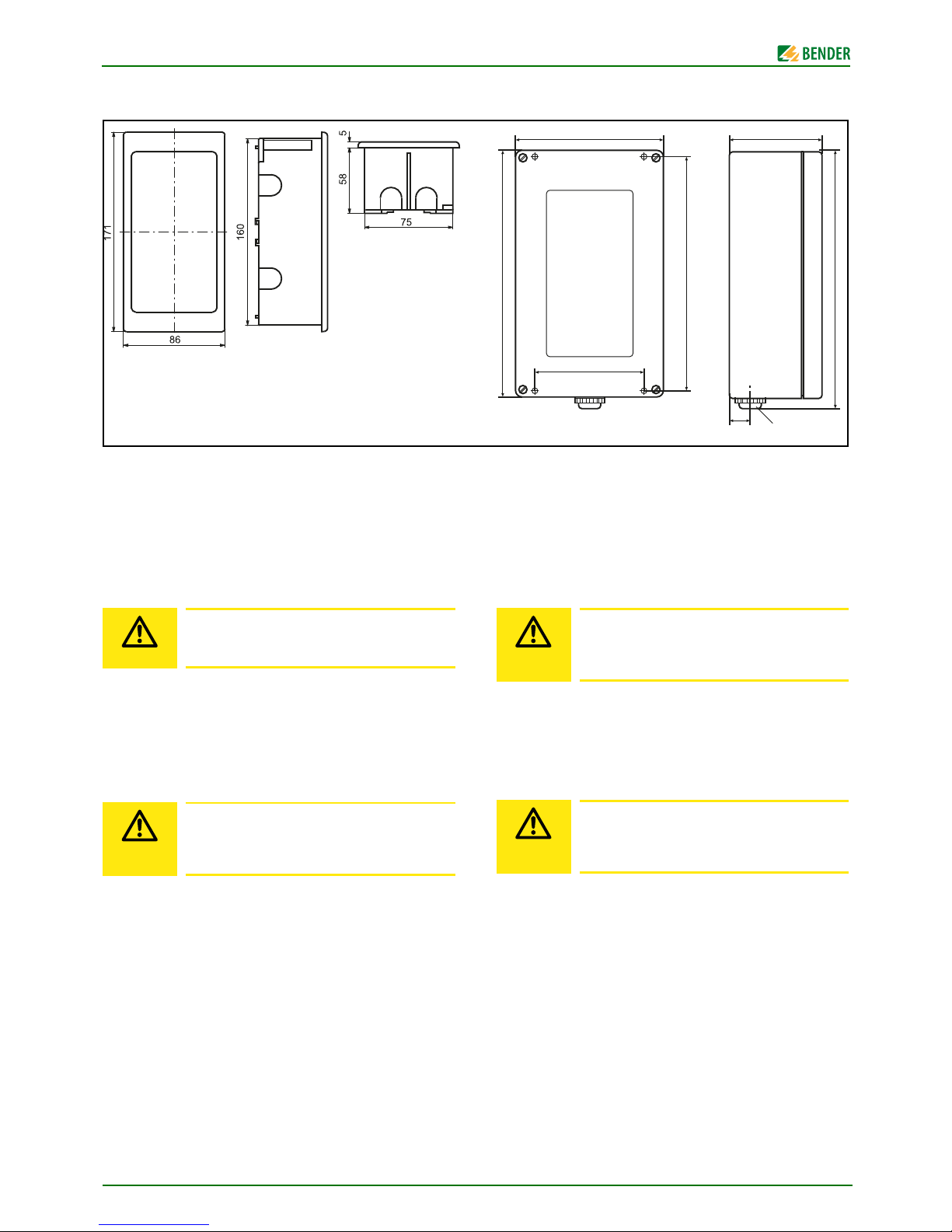
Overview of enclosure variants
All dimensions in mm;
MK2430 in flush-mounting enclosure
Front panel cut-out: 161 x 77 mm
MK2430A Surface mounting enclosure
Installation
Flush-mounting
The flush-mounting enclosure is within the scope of delivery of
the MK2430.
1. Insert the cardboard that has been supplied into the flushmounting enclosure to stabilise the enclosure and to provide protection against pollution.
2. Insert the enclosure so that it is flush with the wall surface.
Surface-mounting
1. Use the empty enclosure as a template for marking the
drilling holes.
2. Install the enclosure. Maximum diameter of the screws:
Thread of screw 3 mm, bolt head 7 mm
Installation variants using the MK2430 mounting kit,
Art. No. B95101000:
● Cavity wall, panel or DIN rail mounting of the flush-mount-
ing enclosure.
● Using the mounting brackets (attached on each side) the
MK2430 snaps into the flush-mounting enclosure. Two
mounting angles (M) provide additional support. They are
needed in particular if the MK2430 is to be fixed into an
existing flush-mounting enclosure (e.g. MK2418) which is
not intended for snap-on mounting (see MK2430 manual).
The MK2430 may be damaged due to incorrect installation. The flush-mounting enclosure must not
be installed lopsidedly or warped, and must not be
installed too deep below the surface.
The MK2430A may be damaged due to incorrect
installation. A smooth and even surface is a precondition for installation. Only the fastening
screws specified below should be used.
CAUTION
CAUTION
Übersicht Gehäusevarianten
Alle Maße in mm;
MK2430 Unterputzgehäuse,
Frontplattenausschnitt: 161 x 77 mm
MK2430A Aufputzgehäuse,
Montage
Unterputzmontage
Das Unterputzgehäuse ist im Lieferumfang der MK2430 bereits
enthalten.
1. Setzen Sie die mitgelieferte Pappe in das Unterputzgehäuse. Auf diese Weise werden Formstabilität und Schutz
vor Verschmutzung während des Einputzens sichergestellt.
2. Mit der fertigen Wandfläche bündig einbauen.
Aufputzmontage
1. Nutzen Sie das leere Gehäuse als Schablone zum Anzeichnen der Bohrungen.
2. Gehäuse montieren. Maximaler Durchmesser der Befestigungsschrauben: Gewinde: 3 mm, Schraubenkopf: 7 mm
Einbauvarianten mit Hilfe des MK2430-Montage-Sets,
Art.-Nr. B95101000:
● Hohlwand-, Schalttafel- oder Hutschienenmontage des
Unterputzgehäuses.
● MK2430 rastet mit seitlich angebrachten Klammern in das
Unterputzgehäuse ein. Zwei Montagewinkel sorgen für
zusätzlichen Halt. Sie werden insbesondere benötigt,
wenn MK2430 in bestehende Unterputzgehäuse (z. B.
MK2418) eingebaut werden sollen, die nicht für Schnappbefestigung vorgesehen sind (siehe Handbuch MK2430).
MK2430 kann durch falschen Einbau beschädigt
werden. Das Unterputzgehäuse darf nicht schief,
nicht verformt und nicht zu tief eingebaut werden.
MK2430A kann durch falschen Einbau beschädigt
werden. Voraussetzung für die Montage ist eine
gerade und ebene Fläche. Verwenden Sie nur Befestigungsschrauben der angegebenen Größe.
120
88
200
188
209,5
17 PG 13,5
75
MK2430
MK2430A
VORSICHT
VORSICHT
 Loading...