

Page 1
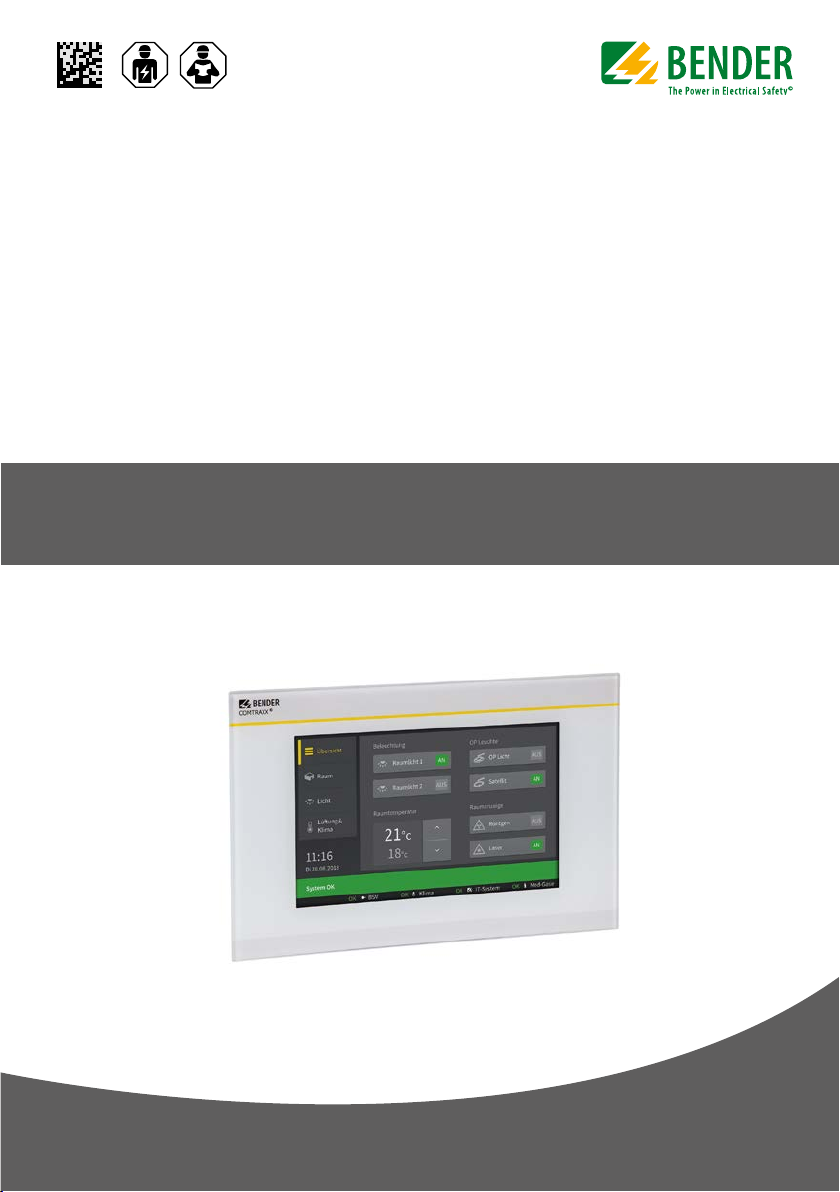
COMTRAXX® CP9… – Control Panel
Melde- und Bedientableau für medizinische und andere Bereiche
Kurzanleitung / Quickstart DE/ENCP9xx_D00349_06_Q_DEEN / 12.2019
Page 2

COMTRAXX® CP9… – Control Panel
COMTRAXX® CP9…
Grafikschnittstelle zur Bedienung und Überwachung
von medizinischen und anderen technischen Anlagen.
Kurzanleitung für folgende Geräte:
Type Display Supply voltage Us* B x H x T / W x H x D Weight Art.-No.
CP907 7“ (17,6 cm) DC 24 V , < 15 W; 226 x 144 x 78 mm 1,2 kg B95061080 (Front white)
CP915 15,6“ (38,6 cm) AC 100…240 V, < 30 W 505 x 350 x 95 mm 6,1 kg
CP924 24“ (54,5 cm) AC 100…240 V, < 55 W 654 x 441 x 100 mm 9,1 kg comming soon
Bestandteil der Gerätedokumentation sind neben
i
dieser Kurzanleitung die beiliegenden „Sicherheitshinweise für Bender-Produkte“ und das
Handbuch, herunterladbar unter https://www.bender.de/service-support/downloadbereich. Die
Kurzanleitung ersetzt nicht das Handbuch.
Bestimmungsgemäße Verwendung
Das Gerät CP9xx findet überall Einsatz, wo komplexe
Informationen für einen Anwender einfach und überschaubar dargestellt werden sollen. Durch die berührungsempfindliche Fläche dient es auch als
Steuerungsmöglichkeit von Anlagen.
Eine andere oder darüber hinausgehende Benutzung
gilt als nicht bestimmungsgemäß.
Sicherheitshinweise allgemein.
VORSICHT! Funktionserde. Das Gerät ist zwin-
gend zu erden. Ohne Anschluss der Funktions-
I
erde ist die Gerätefunktion nicht gewährleistet.
Elektrostatisch gefährdete Bauelemente. Beachten Sie die Vorsichtsmaßnahmen für den
Umgang mit elektrostatisch gefährdeten Geräten.
Beschädigung von Bauteilen. Nehmen Sie das
Gerät nicht im laufenden Betrieb aus dem Gehäuse. Trennen Sie vorher das Gerät von der
Versorgungsspannung und vom Netzwerk
(Ethernet).
Falsche Anschlussstecker. Anschlussstecker
anderer Geräts können eine abweichende Polung aufweisen. Verwenden Sie nur den beigelegten Anschlussstecker (A1+/A2–/PE).
Sichere Trennung. Die Stromversorgung muss
ordnungsgemäß von gefährlichen Spannungen getrennt sein und die Grenzwerte der
UL/CSA 6101010-1, Klausel 6.3 erfüllen.
COMTRAXX® CP9…
Graphical interface for operation and monitoring of
medical and other technical installations.
Quickstart for following devices:
B95061081 (Front white)
B95061085 (Front grey)
Part of the device documentation in addition to
i
this quickstart is the enclosed “Safety instructions
for Bender products“ and the manual, downloadable at https://www.bender.de/en/service-support/
downloads. The quick-start guide does not replace
the operating manual.
Intended use
The Device CP9xx is used wherever complex information needs to be displayed easily and clearly for a
user. Due to its touch-sensitive surface, it can also be
used as a control option for installations.
Any other use than that described in this manual is
regarded as improper.
General safety instructions
CAUTION! Functional ground. The device must
be earthed. Without connection of the functio-
I
nal earth, the device function is not guaranteed.
Electrostatic sensitive devices. Observe precautions for handling electrostatic sensitive devices.
Damage to components. Do not remove the
device from the enclosure during ongoing operation. First, disconnect the device from the
supply voltage and from the network (Ethernet).
Incorrect connector plugs. Connector plugs of
another devices may have a different polarity.
Please only use the supplied connector plug
(A1+/A/2-/PE).
Safe separation. The supply shall be properly
separated from hazardous voltages and meet
the limits of UL/CSA 61010-1, Clause 6.3.
2 CP9xx_D00349_06_Q_DEEN / 12.2019
Page 3
COMTRAXX® CP9… – Control Panel
a
Montage und Anschluss
GEFAHR! Lebensgefahr durch Stromschlag! Bei
Berühren von unter Spannung stehender
I
Anlagenteile besteht die Gefahr eines elektrischen Schlages. Stellen Sie vor Einbau des
Gerätes und vor Arbeiten an den Anschlüssen
des Gerätes sicher, dass die Anlage spannungsfrei ist. Beachten Sie die Regeln für das Arbeiten
an elektrischen Anlagen.
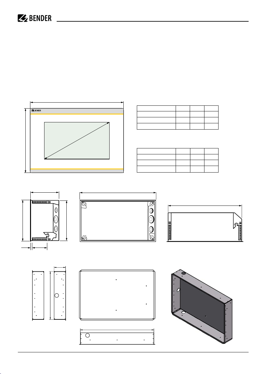
Gerätemaße
COMTRAXX®
cb
75
216
Installation and connection
RISK of fatal injury due to electric shock!
Touching live parts of the system carries the risk
I
of electric shock. Before installing and connecting the device, make sure that the installation
has been de-energised. Observe the rules for
working on electrical installations.
Device dimensions
mm ±1 CP 907 CP 915 CP 924
a 226 505 654
b 144 350 441
c 176 386 545
Maße Wandausschnitt
Dimensions wall cut-out
mm ±1 CP 907 CP 915 CP 924
Breite /Width 212 462 612
Höhe / Height 124 308 400
Tiefe / Depth 75 92 95
Installation flush-mounting box CP907Wandeinbaukasten CP907
212
128
377
124
Maße in mm / Dimensions in mm
Wandeinbaukasten CP915 / CP924 Installation flush-mounting box CP915 / 924
92 / 95
306 / 398
461 / 610
Maße in mm / Dimensions in mm
CP9xx_D00349_06_Q_DEEN / 12.2019 3
Page 4

COMTRAXX® CP9… – Control Panel
1
2
3
5
6
7
8
13
11
10
9
4
12
Anschlussübersicht
COMTRAXX®
+
–
~
BMS-Bus
Modbus RTU
Ethernet
Anschlüsse an die Hauptplatine CP9...
...
1 2
Digital I/O
Relais / Relay
11 12 14
USB
Connectionoverview
12
COMTRAXX®
Ethernet (1:1)
Connections on the mainboard CP9...
Legende
1
Steckbuchse für digitale Eingänge
2
I²C-Schnittstelle
3
Steckbuchse zur Energiespeicherplatine
4
Backbone Bus (nicht bestückt)
5
Spannungsversorgung A1/+, A2/–, PE
6
Ethernet (RJ45 PoE); HTTP; Modbus TCP, BCOM
7
X1-Stecker für Modbus RTU und BMS-Bus
8
Terminierung von Modbus RTU und BMS-Bus
9
USB-Anschlüsse (für Touch Sensor) / CP907 nicht bestückt
10
DVI-Eingang / CP907 nicht bestückt
11
Audio Ausgang / CP907 nicht bestückt
12
Audio Eingang/ CP907 nicht bestückt
13
Anschluss Steuerrelais
Für UL-Anwendungen mind. 75°C-Kupferleitungen
i
verwenden! Für PoE mind. 80°C-Kupferleitungen
verwenden.
4 CP9xx_D00349_06_Q_DEEN / 12.2019
Legend
1
Connector for digital Inputs
2
I²C-interface
3
Connector to energy storage board
4
Backbone Bus (unloaded)
5
Voltage supply A1/+, A2/–, PE
6
Ethernet (RJ45 PoE); HTTP; Modbus TCP, BCOM
7
X1 plug for Modbus RTU and BMS-Bus
8
Termination of Modbus RTU and BMS-Bus
9
USB ports (for Touch Sensor) / CP907 unloaded
10
DVI-Port / CP907 unloaded
11
Audio Output / CP907 unloaded
12
Audio Inputs / CP907 unloaded
13
Connection to control relay
For UL applications use at least 75 °C copper lines!
i
Use at least 80°C copper lines for PoE.
Page 5

COMTRAXX® CP9… – Control Panel
SBMS
ABMS
BBMS
AMB BMB
SMB
1 234 567 8910 11
12
LL
KK
L1
L2
L12
N/O
141211
Belegung der Steckanschlüsse
Belegung X1-Stecker (7)
X1 plug connector (7)
AMB BMB
SMB
ABMS
BBMS
SBMS
Belegung digitale Eingänge (1)
Assignment of digital inputs (1)
...
N/O
N/C
1 234 567 8910 11
12
K1
K12
K2
Inbetriebnahme
Benötigte Informationen VOR einer Inbetriebnahme:
• DHCP-Server verfügbar für CP9… und andere
BCOM- Geräte?
• Feste IP-Adressen für Modbus-Geräte
(z. B. IOM750-xxx)
• Subnetz-Maske
• IP-Adresse vom Standard-Gateway
• IP-Adresse vom DNS-Server
Ist ein DHCP-Server im Netzwerk vorhanden, kann die
Adressierung des Geräts automatisch vorgenommen
werden.
Bildschirm Erstinbetriebnahme
Eingabe einer manuellen Adresse:
• Spannungsversorgung einschalten
• IP-Adresse für das CP9… eingeben
• Subnetzmaske des LAN eingeben
• Gatewayadresse des LAN eingeben
• Eingaben speichern mit der „Save“-Taste
• Warten Sie 8-10 Sekunden
Aktivierung des Adressempfangs von einem DHCPServer
• Aktivieren Sie „DHCP?“
• Eingaben speichern mit der „Save“-Taste
• Warten Sie 8-10 Sekunden
Connections on the mainboard CP915
Terminierung Modbus RTU und BMS-Bus (8)
Termination of Modbus RTU and BMS-bus (8)
Modbus RTU BMS-Bus
Steuerrelais / Control relay (13)
Commissioning
Required information BEFORE commissioning:
• DHCP server available for CP9… and other
BCOM devices?
• Fixed IP addresses for Modbus devices
(e.g. IOM750-xxx)
• Subnet mask
• IP address of the standard gateway
• IP address of the DNS server
If a DHCP server is available in the network, the device
address can be assigned automatically.
Initial commissioning of screen
Entering a manual address:
• Switch on the supply voltage
• Enter the desired IP address for the CP9…
• Enter the subnet mask of the LAN
• Enter the gateway address of the LAN
• Press the „Save“ button to store the entries
• Wait 8-10 seconds
Activating address reception via a DHCP server
• Activate „DCHP?“ checkbox
• Press the „Save“ button to store the entries
• Wait 8-10 seconds
CP9xx_D00349_06_Q_DEEN / 12.2019 5
Page 6

COMTRAXX® CP9… – Control Panel
Anmeldung am Gerät
Aus einem lokalen Netzwerk LAN
• Öffnen Sie einen Browser auf einem im Netzwerk
eingebundenen Gerät (Computer/Laptop)
• Geben Sie im Adressfeld des Browsers die Adresse
der 1. Zeile des CP9… ein
Mittels direkt verbundenem PC (1:1-Verbindung)
Es ist möglich das CP9… direkt mit einem Computer/
Laptop zu verbinden. In diesem Falle lässt sich das
CP9… über eine zweite feste IP-Adresse ansteuern.
• Browser auf verbundenem Gerät öffnen
• Geben Sie in der Adresszeile des Browsers folgende
Adresse ein: 169.254.0.1
COMTRAXX® Startbildschirm
CP900
COMTRAXX®
HOME
BUS OVERVIEW
ALARMS
TOOLS
Device info
Comtraxx CP900 V3.0
1207990020-Bxxxxxxxx
Text
Login to the device
From a local network LAN
• Open a browser on a device (computer/laptop)
that is integrated into the network
• Enter the address indicated in line 1 of the CP9…
into the address field of the browser
From a peer to peer network (1:1 connection)
It is possible to connect the CP9… directly to a com-
puter/laptop. In this case, the CP9… can be controlled
with a second fixed IP address.
• Open browser on the connected device
• Enter the following address into the address line of
the browser: 169.254.0.1
COMTRAXX® Start screen
Text ...
18.07.2017 13:30
EN
System OK
6 CP9xx_D00349_06_Q_DEEN / 12.2019
Page 7

COMTRAXX® CP9… – Control Panel
Technische Daten
CP907
Display .....................................................................7“ (176 mm)
Front ......................................................................Glas, gehärtet
Versorgungsspannung ............................... DC 24 V, PoE, < 15 W
Maße..............................................................226 x 144 x 78 mm
Gewicht ..............................................................................1,1 kg
CP915
Display ...................................................................15“ (386 mm)
Front ...................................................Glas, gehärtet, weiß/grau
Versorgungsspannung ........................ AC 100…240 V / < 30 W
Maße..............................................................505 x 350 x 92 mm
Gewicht ...............................................................................6,1kg
CP924
Display ...................................................................24“ (545 mm)
Front ......................................................................Glas, gehärtet
Versorgungsspannung ........................ AC 100…240 V / < 55 W
Maße............................................................654 x 441 x 100 mm
Gewicht ..............................................................................9,1 kg
Weitere Bestellnummern
Ersatzteile
Gerät Zubehör Bestellnummer
CP907 UP-Gehäuse B95100140
CP915 Displayeinheit, weiß B95061090
Displayeinheit, grau B95061110
UP-Gehäuse incl. Montageplatte mit
Elektronik
CP924 Displayeinheit, weiß Demnächst
Displayeinheit, grau Demnächst
UP-Gehäuse incl. Montageplatte mit
Elektronik
alle CP9… Ersatz-Steckerkit B95061910
CP915/24 CP9… Saugheber B95061911
B95061092
Demnächst
Technical data
CP907
Display .................................................................... 176 mm (7“)
Front ...................................................................glass, tempered
Supply voltage ...........................................DC 24 V, PoE, < 15 W
Dimensions ....................................................226 x 144 x 78 mm
Weight ............................................................................... 1.1 kg
CP915
Display ...................................................................381 mm (15“)
Front ...............................................glass, tempered, white/grey
Supply voltage ....................................AC 100…240 V / < 30 W
Dimensions ....................................................505 x 350 x 92 mm
Weight ................................................................................ 6.1kg
CP924
Display ...................................................................545 mm (24“)
Front ...................................................................glass, tempered
Supply voltage ....................................AC 100…240 V / < 55 W
Dimensions ..................................................654 x 441 x 100 mm
Weight ............................................................................... 9.1 kg
Other Order numbers
Spare parts
Device Accessories Order number
CP907 Flush-mounting enclosure B95100140
CP915 Displayunit, white B95061090
Displayunit, grey B95061110
Flush-mounting enclosure with
mounting plate and electronics
CP924 Displayunit, white comming soon
Displayunit, grey comming soon
Flush-mounting enclosure with
mounting plate and electronics
All CP9… replacement plug connector kit B95061910
CP915/24 CP9… vacuum lifter B95061911
B95061092
comming soon
CP9xx_D00349_06_Q_DEEN / 12.2019 7
Page 8

Alle Rechte vorbehalten.
Nachdruck und Vervielfältigung
nur mit Genehmigung des Herausgebers.
All rights reserved.
Reprinting and duplicating
only with permission of the publisher.
Bender GmbH & Co. KG
Postfach 1161 • 35301 Grünberg • Deutschland
Londorfer Str. 65 • 35305 Grünberg • Deutschland
Tel.: +49 6401 807-0 • Fax: +49 6401 807-259
E-Mail: info@bender.de • www.bender.de
PO Box 1161 • 35301 Gruenberg • Germany
Bender GmbH & Co. KG
Londorfer Str. 65 • 35305 Gruenberg • Germany
Tel.: +49 6401 807-0 • Fax: +49 6401 807-259
E-Mail: info@bender.de • www.bender.de
CP9xx_D00349_06_Q_DEEN / 12.2019/ pdf / © Bender GmbH & Co. KG, Germany – Subject to change! The specied standards take into account the edition valid until 11/2019 unless otherwise indicated.
 Loading...