

Page 1

Manual
EN
COMTRAXX® CP700
Condition Monitor
for the connection of Bender BMS devices
and universal measuring devices
to TCP/IP networks
Software version: V1.8
CP700_D00005_02_M_XXEN/06.2014
Page 2

Bender GmbH & Co. KG
P.O.Box 1161 • 35301 Grünberg • Germany
Londorfer Straße 65 • 35305 Grünberg • Germany
Tel.: +49 6401 807-0 • Fax: +49 6401 807-259
E-mail: info@bender.de • www.bender.de
Photos: Bender archives and bendersystembau archives.
© Bender GmbH & Co. KG
All rights reserved.
Reprinting only with permission
of the publisher.
Subject to change!
Page 3

Table of Contents
1. Making effective use of this document ............................................................... 9
1.1 How to use this manual ......................................................................................................... 9
1.2 Quick start ................................................................................................................................... 9
2. Safety instructions ............................................................................................... 11
2.1 Work activities on electrical installations ..................................................................... 11
2.2 Intended use ........................................................................................................................... 11
2.3 Address setting and termination .................................................................................... 12
2.4 Delivery conditions, guarantee, warranty and liability ........................................... 12
3. Product description ............................................................................................. 13
3.1 Scope of supply ..................................................................................................................... 13
3.2 Device features ...................................................................................................................... 13
3.3 Possible applications ........................................................................................................... 13
3.4 Description of function ....................................................................................................... 14
3.4.1 Interfaces .................................................................................................................................. 14
3.4.2 Process image ........................................................................................................................ 14
3.4.3 CP700-compatible devices ................................................................................................ 14
3.4.4 Functions available via touch screen ............................................................................. 15
3.4.5 Functions available via the web user interface .......................................................... 15
3.5 Software products used ...................................................................................................... 16
4. Installation, connection and commissioning .................................................. 17
4.1 Preliminary considerations ................................................................................................ 17
4.2 Installing the device ............................................................................................................. 17
4.2.1 Essential information on mounting ............................................................................... 17
4.2.2 Type of installation ............................................................................................................... 18
4.2.3 Practice ..................................................................................................................................... 18
4.3 Connection of the device ................................................................................................... 20
4.3.1 Overview of the bus device interfaces .......................................................................... 20
4.3.2 DC 24 V power supply ........................................................................................................ 21
4.3.3 Earthing .................................................................................................................................... 21
4.3.4 BMS bus, Modbus/RTU ........................................................................................................22
4.4 Commissioning ...................................................................................................................... 23
CP700_D00005_02_M_XXEN/06.2014
3
Page 4

Table of Contents
5. Display and operating elements ....................................................................... 25
5.1 Operating elements at the rear of the device ............................................................. 25
5.1.1 Status LEDs ............................................................................................................................... 26
5.1.2 Battery ....................................................................................................................................... 26
5.1.3 CompactFlash card ............................................................................................................... 26
5.2 Touchscreen ............................................................................................................................ 27
5.3 Operation via touch screen ................................................................................................ 28
5.3.1 Main menu ............................................................................................................................... 28
5.3.2 "Settings" menu ..................................................................................................................... 29
5.3.2.1 "Interface" menu ............................................................................................................. 29
5.3.2.2 "Language" menu ........................................................................................................... 31
5.3.3 "Alarms" menu ........................................................................................................................ 32
5.3.4 "Bus overview" menu ........................................................................................................... 32
5.3.5 Displaying the device info for CP700 ............................................................................. 33
5.3.6 Using the functions for Bender PEM… universal measuring devices ............... 33
6. Web user interface of the CP700 ....................................................................... 35
6.1 Menu structure of the web user interface .................................................................... 35
6.2 Browser configuration ......................................................................................................... 37
6.3 Initial operation of the web user interface: .................................................................. 37
6.4 Start page and operating language ................................................................................ 38
6.4.1 Opening the start page ....................................................................................................... 38
6.4.2 Changing the language ....................................................................................................... 38
6.5 Menu bar ................................................................................................................................... 39
6.6 Bus overview and device information ........................................................................... 40
6.6.1 Creating a password protection for CP700 .................................................................. 40
6.6.2 Buttons for the list of bus devices ................................................................................... 42
6.6.3 CP700 on the internal BMS bus ........................................................................................ 43
6.6.4 Querying device information ............................................................................................ 43
6.6.5 Displaying the help text ...................................................................................................... 44
6.6.6 Loading the menu of a bus device .................................................................................. 45
6.6.7 Displaying the settings of a bus device ......................................................................... 45
6.6.8 Creation and further processing of a bus device Back-up/Report ....................... 46
6.6.8.1 Creating a backup ........................................................................................................... 46
6.6.8.2 Show the backup ............................................................................................................ 47
6.6.8.3 Creating a new backup with a comparison of the device parameters ........ 47
6.6.8.4 Using a backup for parameter setting .................................................................... 48
6.6.9 History memory ...................................................................................................................... 50
6.6.9.1 Displaying the history memory ................................................................................. 50
6.6.9.2 Evaluating the history memory ................................................................................. 51
4
CP700_D00005_02_M_XXEN/06.2014
Page 5

Table of Contents
6.6.9.3 Exporting the history memory .................................................................................. 52
6.6.9.4 Delete the history memory ......................................................................................... 52
6.6.9.5 Displaying the history memory of BMS devices ................................................. 52
6.6.10 Data logger .............................................................................................................................. 53
6.6.10.1 Data logger setting ........................................................................................................ 53
6.6.10.2 Displaying the data logger ......................................................................................... 53
6.6.10.3 Evaluating the data logger ......................................................................................... 54
6.6.10.4 Apply the filter to the graphical representation ................................................. 58
6.6.10.5 Exporting the data logger ........................................................................................... 58
6.6.10.6 Deleting the data logger ............................................................................................. 59
6.6.10.7 Displaying the data logger of BMS devices .......................................................... 59
6.7 Parameter setting for bus devices .................................................................................. 60
6.7.1 Operating elements for parameter setting ................................................................. 60
6.7.2 Setting the parameters for RCMS460-L ......................................................................... 61
6.7.3 Parameter setting of the CP700 using the "Settings" menu ................................. 62
6.8 Entering individual texts ....................................................................................................65
6.8.1 Enter individual texts for an RCMS460-L ...................................................................... 65
6.8.2 Displaying, filtering, exporting and importing individual texts ........................... 67
6.8.2.1 Displaying individual texts ......................................................................................... 67
6.8.2.2 Filtering entries ............................................................................................................... 67
6.8.2.3 Exporting individual texts ........................................................................................... 68
6.8.3 Editing and importing individual texts ......................................................................... 69
6.9 E-mail notification in the event of an alarm ................................................................ 71
6.9.1 Create templates: To whom and when is an e-mail to be sent ............................ 71
6.9.2 Select devices and channels that are to trigger an e-mail notification ............. 74
6.9.3 Displaying an e-mail overview ......................................................................................... 75
6.10 Using the device failure monitoring function ............................................................ 76
6.10.1 Activating/deactivating device failure monitoring function
6.10.2 Displaying overview device failure monitoring
6.11 Alarms ....................................................................................................................................... 80
6.12 Tools ........................................................................................................................................... 81
6.12.1 BMS recording ........................................................................................................................ 82
6.12.2 BMS analyser ........................................................................................................................... 83
6.12.3 BMS Log files ........................................................................................................................... 86
6.12.4 Network parameters ............................................................................................................ 86
6.12.5 Socket state ............................................................................................................................. 87
6.12.6 Software update .................................................................................................................... 88
6.12.7 Software options and licensing ....................................................................................... 90
6.12.7.1 Identifying activated software options .................................................................. 90
in the bus overview .............................................................................................................. 77
and adding devices ..............................................................................................................78
CP700_D00005_02_M_XXEN/06.2014
5
Page 6

Table of Contents
6.12.7.2 Acquiring licences for additional software options and loading the licence
file ......................................................................................................................................... 91
6.12.7.3 Activate acquired software options ......................................................................... 92
6.12.8 Modbus register ..................................................................................................................... 93
6.12.8.1 Modbus representation of device information .................................................... 93
6.12.8.2 Modbus representation of a BMS channel ............................................................ 94
6.12.9 Modbus control commands for BMS devices .............................................................. 95
6.12.10Individual texts, device failure monitoring, e-mail configuration ....................... 96
6.13 Visualisation ............................................................................................................................. 97
6.13.1 Create visualisation ............................................................................................................... 97
6.13.1.1 Creating a new view page ........................................................................................... 99
6.13.1.2 Adding a link to view pages ..................................................................................... 101
6.13.1.3 Adding new elements ................................................................................................ 102
6.13.1.4 Adding a new text line ............................................................................................... 104
6.13.1.5 Adding a new data logger ........................................................................................ 105
6.13.2 Save, export, import and exit configuration ............................................................. 106
6.13.2.1 Save and exit configuration ..................................................................................... 106
6.13.2.2 Export configuration ................................................................................................... 106
6.13.2.3 Import configuration .................................................................................................. 106
6.13.3 Using the visualisation function .................................................................................... 107
6.13.4 Open the operating manual as PDF file ..................................................................... 109
6.13.5 System visualisation .......................................................................................................... 110
6.13.5.1 Start system visualisation ......................................................................................... 110
6.13.5.2 Check the activation of the application memory ............................................. 110
6.13.5.3 Add new device to system visualisation ............................................................. 111
6.13.5.4 Change or delete the device .................................................................................... 111
6.13.5.5 Export system visualisation ...................................................................................... 112
6.13.5.6 Import system visualisation ..................................................................................... 112
6.13.5.7 Sort system visualisation ........................................................................................... 112
6.13.5.8 Use system visualisation ............................................................................................ 113
6.14 Manage Modbus devices ................................................................................................. 114
6.14.1 Adding a new Modbus device ....................................................................................... 114
6.14.2 Delete Modbus device ......................................................................................................115
6.14.3 Editing a Modbus device ................................................................................................. 115
6.14.4 Creating, editing or deleting templates ..................................................................... 115
6.14.4.1 Add new template ....................................................................................................... 116
6.14.4.2 Delete template ............................................................................................................ 116
6.14.4.3 Change template .........................................................................................................116
6.15 Manage virtual devices ..................................................................................................... 117
6.15.1 Adding a new virtual device ........................................................................................... 117
6.15.2 Deleting a virtual device .................................................................................................. 118
6
CP700_D00005_02_M_XXEN/06.2014
Page 7

Table of Contents
6.15.3 Changing a virtual device ................................................................................................ 118
6.15.4 Setting the channels of a virtual device ...................................................................... 119
7. Data access using the Modbus/TCP protocol ............................................... 121
7.1 Exception code .................................................................................................................... 121
7.2 Modbus requests ................................................................................................................ 121
7.3 Modbus responses .............................................................................................................122
7.4 Structure of an exception code ..................................................................................... 122
7.5 Modbus address structure for BMS devices .............................................................. 122
8. Process image in the memory of the CP700 ................................................. 123
8.1 Data request ......................................................................................................................... 123
8.1.1 Modbus function code ...................................................................................................... 123
8.1.2 How are memory areas organised? .............................................................................. 123
8.2 Memory scheme of the process image ...................................................................... 124
8.2.1 BMS device address assignment within the Modbus ............................................ 124
8.2.2 Memory scheme of an individual BMS device .......................................................... 124
8.2.3 Device type ............................................................................................................................ 126
8.2.4 Timestamp ............................................................................................................................. 126
8.2.5 C = Common alarm and D = Device lost (device failure) ...................................... 126
8.2.6 Channels 1 to 32 with analogue and/or digital values .......................................... 126
8.2.6.1 Float = Floating point value of the BMS channels ........................................... 127
8.2.6.2 A&T = Alarm type and test type (internal) .......................................................... 127
8.2.6.3 R&U = Range and unit ................................................................................................ 128
8.2.6.4 Channel description .................................................................................................... 129
8.2.6.5 Channel 33 to 64 .......................................................................................................... 130
8.3 Reference data records of the process image .......................................................... 131
8.3.1 Address assignment of the reference data record .................................................. 131
8.3.2 Reference value on channel 1 ........................................................................................ 131
8.3.3 Reference value on channel 2 ........................................................................................ 132
8.3.4 Explanation of how to access floating point values ............................................... 132
8.4 Channel descriptions for the process image ............................................................ 133
8.5 Modbus control commands for BMS devices ........................................................... 138
9. Monitor for Power quality ................................................................................ 141
9.1 Displaying alarms/measured values ............................................................................ 141
9.2 Triggering alarm messages in the case of events ................................................... 142
9.2.1 Making settings for events .............................................................................................. 142
9.2.1.1 Creating template for events ................................................................................... 142
9.2.1.2 Activate template for events .................................................................................... 143
CP700_D00005_02_M_XXEN/06.2014
7
Page 8

Table of Contents
9.2.2 Acknowledging alarm messages for events ............................................................. 143
9.2.3 Acknowledging alarm messages for events ............................................................. 143
9.3 Displaying a PEM…'s voltages/currents .................................................................... 144
9.4 Displaying the phasor diagram of a PEM… .............................................................. 145
9.5 Displaying harmonics by means of PEM… ............................................................... 146
9.6 Waveform recorder of a PEM575 universal measuring device .......................... 148
9.6.1 Using the waveform recorder ........................................................................................ 148
9.6.2 Setting the waveform recorder ..................................................................................... 152
9.6.3 Setting the trigger event for the waveform recorder ............................................ 153
9.6.3.1 Setting the trigger event undervoltage/overvoltage (SAG/SWELL) ......... 153
9.6.3.2 Setting the trigger event transients ...................................................................... 154
9.7 Displaying the power diagram of a PEM… ............................................................... 155
9.7.1 Set the options .................................................................................................................... 156
9.8 Data recorders and high-speed data recorders ....................................................... 157
10. Technical data ................................................................................................... 159
10.1 Data in tabular form ........................................................................................................... 159
10.2 Dimension diagram ...........................................................................................................161
10.3 Control panel cut-out ........................................................................................................ 161
10.4 Standards, approvals, certifications ............................................................................. 162
10.5 Ordering information ........................................................................................................162
10.6 Disposal .................................................................................................................................. 162
11. Troubleshooting .............................................................................................. 163
11.1 Damage in transit ............................................................................................................... 163
11.2 Malfunctions ......................................................................................................................... 163
11.2.1 What should be checked? ............................................................................................... 163
11.2.2 Fault messages with error code .................................................................................... 164
11.2.3 Frequently asked questions ............................................................................................ 164
11.2.4 Where do you get help? ................................................................................................... 164
11.2.5 Battery change ..................................................................................................................... 165
INDEX ......................................................................................................................... 167
8
CP700_D00005_02_M_XXEN/06.2014
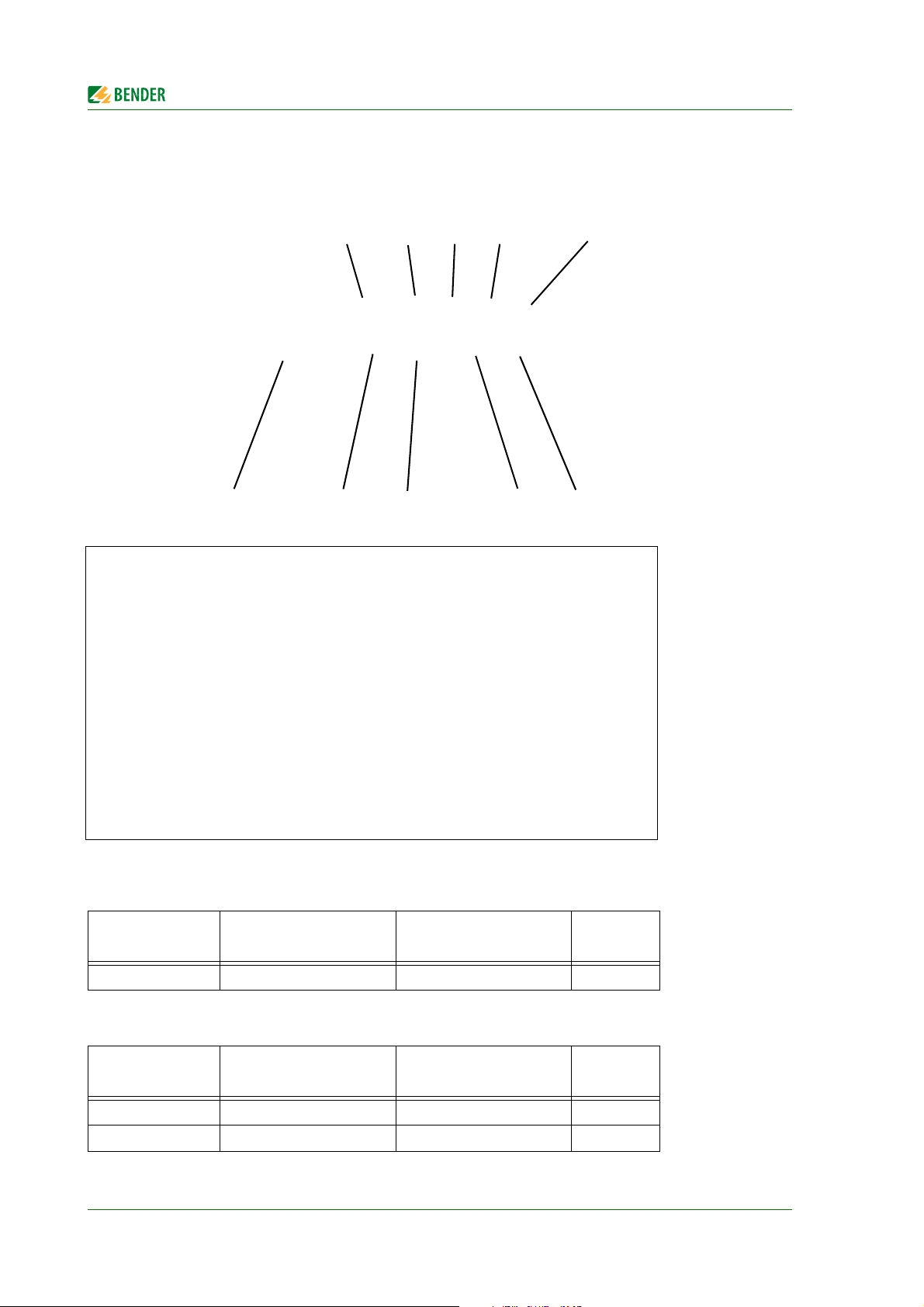
Page 9
1. Making effective use of this document
DANGER
WARNING
CAUTION
1.1 How to use this manual
This operating manual will concern qualified experts in electrical engineering and communication technology!
To make it easier for you to understand and revisit certain sections of text and instructions in the
manual, we have used symbols to identify important instructions and information. The meaning of
these symbols is explained below:
The signal word indicates that there is a high risk danger that will result in electrocution or serious injury if not avoided.
This signal word means that there is a medium risk of danger that can lead to
death or serious injury, if not avoided.
This signal word indicates a low level risk that can result in minor or moderate
injury or damage to property if not avoided.
This symbol denotes information intended to assist the user
to make optimum use of the product.
1.2 Quick start
Connection of the CP700
If you are familiar with the installation and connection of electrical devices as well as networking,
particularly with Ethernet, you can start right away with the wiring diagram on "Connection of the
device" on page 20.
Using the web user interface
You can easily access the CP700 using a standard web browser. For details refer to page 35.
Using the Modbus/TCP functions
Information about this complex field can be found as of page 121.
CP700_D00005_02_M_XXEN/06.2014
9
Page 10

Making effective use of this document
10
CP700_D00005_02_M_XXEN/06.2014
Page 11
2. Safety instructions
DANGER
CAUTION
2.1 Work activities on electrical installations
Risk of fatal injury from electric shock
Any work on electrical installations which is not carried out properly can lead to
death and injury!
► Only skilled persons are permitted to carry out the work necessary to
install, commission and run a device or system.
Compliance with applicable regulations governing work on electrical installations, and with the
regulations derived from and associated with them, is mandatory. EN 50110 is of particular
importance in this regard.
If the device is being used in a location outside the Federal Republic of Germany, the applicable
local standards and regulations must be complied with. European standard EN 50110 can be
used as a guide.
2.2 Intended use
The Condition Monitor CP700 connects the following devices to Ethernet TCP/IP networks:
Devices on the Bender internal serial BMS bus
Bender universal measuring devices PEM… to Modbus/RTU or Modbus/TCP.
The CP700 converts alarms, measured values and statuses into Modbus/TCP protocols and HTTP.
That allows connection to Modbus/TCP networks as well as visualisation and evaluation using standard web browsers with Silverlight
TM
plugin.
The CP700 has been designed, developed and produced for normal use in the industrial sector. The
CP700 has not been designed for use bearing high risks and dangers, which can result in death, injury, serious physical harm or any other loss unless exceptionally high safety measures are ensured.
In particular, its application for the monitoring of nuclear reactions in nuclear power stations, monitoring of flight control systems, for air traffic control, control of means of mass transport, medical life
support systems, and weapon system control involve these risks.
CP700_D00005_02_M_XXEN/06.2014
The device is only suitable for use in the industrial sector. The emissions of the device may exceed the permissible limits for residential, business or commercial areas or small companies.
The CP700 is not intended for use on smartphones or
tablet PCs.
11
Page 12
Safety instructions
CAUTION
2.3 Address setting and termination
In order to ensure proper functioning of the Condition Monitor CP700, correct address assignment
and termination of the connected bus systems according to their specification is of utmost importance.
Assigning addresses that are already used by existing devices on the bus systems
concerned may cause serious malfunctions.
► Ensure correct address setting and termination of the CP700.
2.4 Delivery conditions, guarantee, warranty and liability
The conditions of sale and delivery set out by Bender apply.
Conditions of sale and delivery can be obtained from Bender in printed or electronic format.
The five year guarantee "5forU" does not include parts subject to wear, such as
the touch screen and the battery.
12
CP700_D00005_02_M_XXEN/06.2014
Page 13

3. Product description
3.1 Scope of supply
You will receive:
The CP700
This operating manual as pdf file in the device memory,
accessible via the web user interface under "Tools" > "Manual"
A short operating instruction
A pluggable screw clamp for the voltage supply
Two RS-485 cables for the connection to the BMS bus and the Modbus/RTU, 2 m
Two terminating resistors each for BMS bus and Modbus/RTU (bus termination set)
Four mounting brackets for panel mounting
3.2 Device features
Condition Monitor for Bender BMS devices and universal measuring devices
7“ TFT WVGA Colour Display
Analogue resistive touch screen
Small mounting depth
Fanless operation
Integrated gateway to Ethernet (TCP/IP), 10/100/1000 Mbit/s
Remote access via LAN, WAN or Internet
Support of devices connected to the internal bus via Modbus/RTU or Modbus/TCP
Access to all devices connected to the BMS bus using the web server
Can be operated on Modbus/RTU
History memory for 1000 entries
12 data loggers, freely configurable with 1000 entries each
3.3 Possible applications
Clearly presented information about the status of devices and systems via 7“ touch screen
Specific system overview according to individual system description
Display und visualisation of device and system statuses via web browser
Selective e-mail notification to various user groups in the event of alarms
Support of professional visualisation programs
Observing and analysing of compatible Bender products (universal measuring devices, RCMS,
Isometer, EDS systems)
Parameter setting for devices, storing, documentation and restoring of parameters in a clear
and practice-oriented manner
Remote diagnosis, remote maintenance
CP700_D00005_02_M_XXEN/06.2014
13
Page 14
Product description
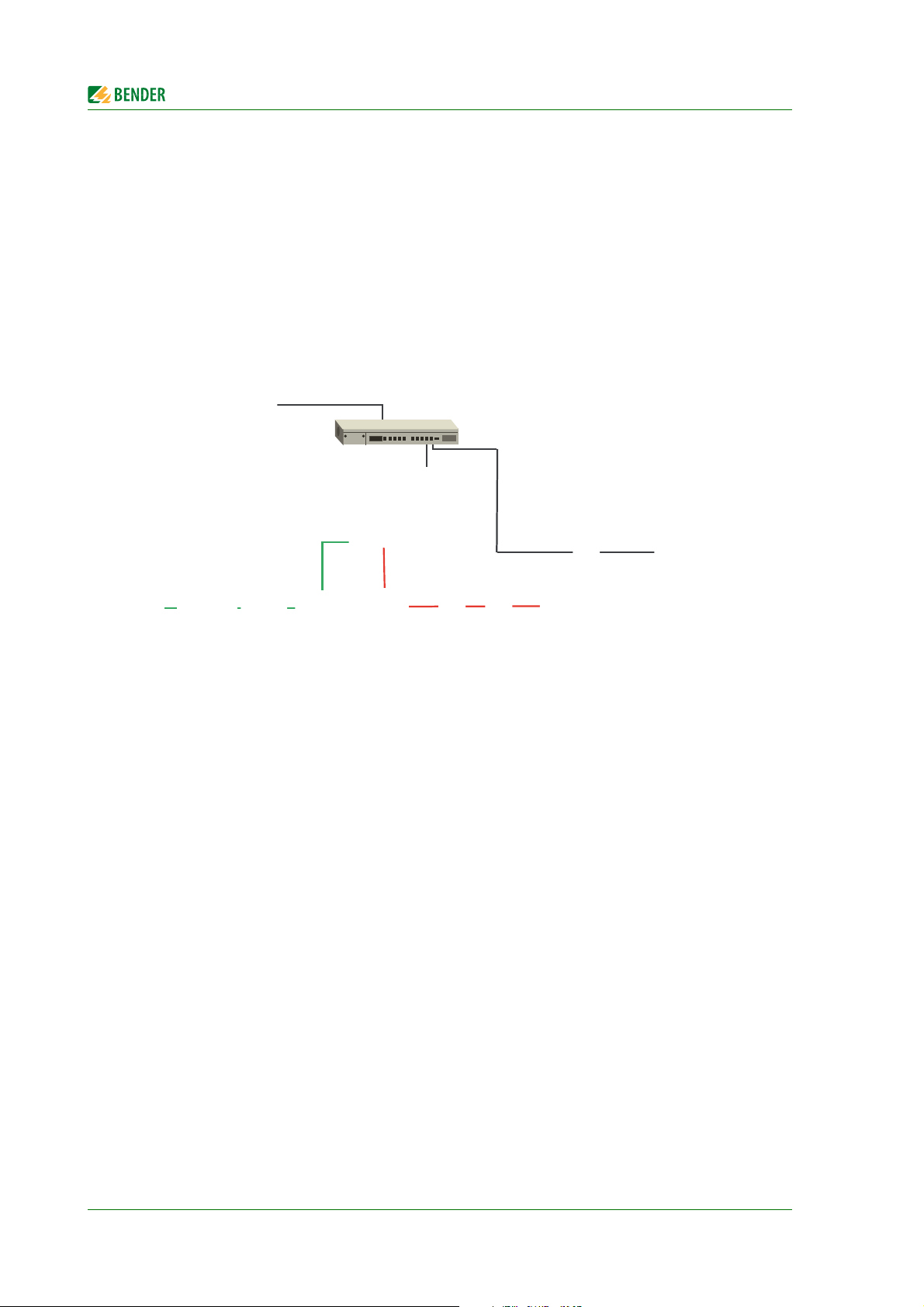
Condition
Monitor
CP700
PEM..5
PEM..3, PEM..5*
Modbus/RTU
Modbus/TCP
BMS-Bus
PC
Ethernet/TCP/IP
3.4 Description of function
3.4.1 Interfaces
The CP700 communicates with the associated devices via three different interfaces:
BMS bus (RS-485) for Bender systems such as EDS46x/49x, RCMS46x/49x and MEDICS. The
CP700 can be operated as master or slave. With the CP700 in master mode, requests can be
answered faster. The CP700 can only be operated on the internal BMS bus.
Modbus/RTU (RS-485) CP700 in master mode for Bender universal measuring devices PEM..3
and also PEM..5 with reduced functionality (*).
Modbus/TCP Ethernet) for Bender universal measuring devices PEM..5
The CP700 can usually be integrated into existing LAN structures, but can also be operated on a single PC via Ethernet/TCP/IP. The CP700 can also be used as master for Bender BMS devices and/or universal measuring devices without being connected to a PC.
3.4.2 Process image
Using the information from communication with the assigned devices, the CP700 creates and saves
a process image. This process image contains all alarms, status information and measured values of
the associated devices.
The CP700 combines the information of three different interfaces and makes it available for:
indication on the integrated touch screen
the operation of a PC via the web user interface
the transmission to external visualisation programs or PLCs via Modbus/TCP.
The CP700 provides a uniform user interface for the devices associated via different interfaces (max.
247 devices). In order to be able to identify each individual device, one individual address is available
for each device on this interface. BMS and Modbus/RTU devices receive the appropriate address for
their interface. A virtual address is assigned to Modbus/TCP devices.
3.4.3 CP700-compatible devices
For an up-to-date list of the Bender BMS devices compatible with CP700 and the universal measuring
devices PEM…. refer to:
http://www.bender-de.com/en/products/system-components/cp700-compatible-devices.html
14
CP700_D00005_02_M_XXEN/06.2014
Page 15

Product description
3.4.4 Functions available via touch screen
Display of current alarm messages including help texts
Bus overview of the assigned devices. Indication of alarm and measured values. Indication of the
interfaces of the devices in use. In case of universal measuring devices, also the indication of the
harmonics in tabular form or as a chart. Waveform recorder and graphical representation of measuring values (bar graph, phasor diagram, power triangle).
Interface settings with password protection
Operating language, selectable
3.4.5 Functions available via the web user interface
The device utilises an integrated web server which can be used to display data in a convenient way
on any PC by means of a web browser and Silverlight
In addition, it provides a Modbus/TCP server which converts data of the associated devices for a
Modbus client. Also, the CP700 contains an FTP server for file access. Functions available via the web
user interface are:
Bus overview of the associated devices (max. 247 devices).
– Indication of alarm and measured values.
– Indication of the interfaces of the devices in use.
– In case of universal measuring devices, also the indication of the harmonics in tabular form
or as a chart. Waveform recorder and graphical representation of measuring values (bar
graph, phasor diagram, power triangle).
– Parameter setting
– Device failure monitoring
– The "Backup/Report" function saves measured values and settings. Saved settings from pre-
vious configurations can be compared with the current settings made on the CP700. The
saved settings can be reloaded into the CP700.
– Assignment of individual texts for devices, measuring points (channels) and alarms.
– E-mail notifications to different user groups according to a time controlled schedule in the
event of alarms and system faults. The sender's e-mail address can be entered.
– Display of virtual devices. A virtual "measuring point" is obtained by evaluating "real" meas-
ured values of devices connected to the CP700 logically or numerically.
Manage Modbus devices
– Adding/deleting devices to/from the bus overview.
– Creating a template with selected measured values
Visualisation
– Fast and simple visualisation without any programming. Measured values or alarms can be
displayed in front of a graphic (system diagram, room plan).
– Displaying an overview page. Click to jump to another view. Return to the overview page.
From an external application (e.g. visualisation software) commands can be sent to BMS devices.
The "Modbus control commands" menu provides Modbus control commands for selected BMS
commands. These commands can be copied to the clipboard of the PC and then included in the
programming for external application.
A graphical representation for the CP700 data logger and compatible Bender devices is avail-
able. The time axis can be varied to view different periods.
TM
plug-in.
CP700_D00005_02_M_XXEN/06.2014
15
Page 16

Product description
System visualisation: Displaying several gateways (COM460IP, CP700) on one website. Display-
ing common alarms of the devices. Clicking on a device being displayed will open its web user
interface.
Displaying the CP700 operating manual
3.5 Software products used
MIT license (http://opensource.org/licenses/mit-license.php)
– jQuery-Scrollbar
–jQuery Timer Plugin
– jQuery NiceScroll Plugin
– jsmn JSON parser (http://zserge.bitbucket.org/jsmn.html)
FJCore and jqPlot under the MIT license (http://www.opensource.org/licenses/mit-license.php)
AES256 implementation:
– Copyright (c) 2007-2009 Ilya O. Levin, ?http://www.literatecode.com
– Other contributors: Hal Finney(modified to AES128)
Silk icons. This work is licensed under a Creative Commons Attribution 2.5 License.
[ http://creativecommons.org/licenses/by/2.5/ ]
GPLv2 license (http://www.gnu.org/licenses/old-licenses/gpl-2.0.html):
mongoose web server (https://code.google.com/p/mongoose/)
GPL 3 (http://code.google.com/p/rootaufs/)
(C) 2008 Kishore Nallan for DesignShack
(http://www.kishorelive.com) kishore.nc@… (jquery Keyboard (modified))
16
CP700_D00005_02_M_XXEN/06.2014
Page 17

4. Installation, connection and commissioning
If you are familiar with the configuration of computer networks, you can carry
out the connection of the CP700 yourself. Otherwise please contact your EDP
administrator!
4.1 Preliminary considerations
1. Have all the questions as regards the installation been answered by the technician responsible
for the installation?
2. Do you know the BMS address to be set?
Can CP700 be operated as the master (BMS address 1)? If apart from the CP700, an alarm indicator and test combination MK800 is connected to the internal bus, the CP700 must not have
address 1 (Master).
You will find more detailed information on the BMS topic, in particular about the wiring of bus
devices, in the separate document "BMS bus". You can download the document from the
download area of the website www.bender.de.
3. Does the computer network comprise a DHCP server?
Otherwise, the network data such as the IP address and netmask allocated by the person
responsible for the electrical installation have to be set manually.
4. Ask for the IP address of the NTP server, which is required for automatic time setting.
5. Are suitable PC hardware and software available for commissioning?
Minimum system requirements: 1.6-GHz prozessor/512 MB RAM/Windows XP/Vista/7/web
browser with Microsoft Silverlight
System requirements (recommended): Dual-Core processor/1024 MB RAM/
Windows XP/Vista/7/web browser with Microsoft Silverlight
For initial connection, the basic configuration of the CP700 is to be undertaken outside the installation, depending on the specific situation.
TM
(version 5.0 or higher).
TM
(version 5.0 and higher)
4.2 Installing the device
4.2.1 Essential information on mounting
Mounting is to be carried out with suitable equipment and tools according to the documenta-
tion.
The device must only be installed by appropriately qualified personnel in de-energised state.
Disconnect the switchboard cabinet from the power supply and protect the system against
accidental switch-on.
The general safety conditions as well as the prevailing national accident prevention regulations
are adhered to. Electrical installation is to be carried out according to all applicable local laws
(e.g. wire cross section, protection, PE connection).
The climatic conditions must be complied with. The device is only permitted to be used in
enclosed rooms. The device must not be exposed to direct sunlight.
CP700_D00005_02_M_XXEN/06.2014
17
Page 18
Installation, connection and commissioning
The device must be installed on a flat surface. While tightening the screws, irregularities may
damage the display.
The ventilation holes must not be covered.
When installing the device, the permissible mounting positions are to be observed.
Take into consideration that the wall or the sheet metal of the switchboard cabinet can hold
four times the total weight of the device.
When connecting the cables it is essential to note the bending radius.
The device should be positioned in such a way that it is visible for the user and that reflexions
on the screen are avoided as far as possible.
4.2.2 Type of installation
The CP700 is preferably installed into consoles and control panel doors using the mounting brackets
supplied with the device. Strength of the material to be clamped: minimum 2 mm, maximum 6 mm.
4.2.3 Practice
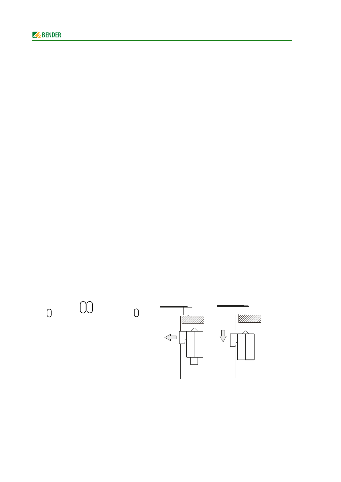
1. Insert the device frontally into the prepared, plane and smooth installation cut-out. The dimensions for the installation cut-outs can be found on page 161.
2. Attach the mounting brackets to the CP700. For this purpose, insert all mounting brackets into
the slots (marked with orange circles) at the CP700 and slide them down.
18
CP700_D00005_02_M_XXEN/06.2014
Page 19
Installation, connection and commissioning
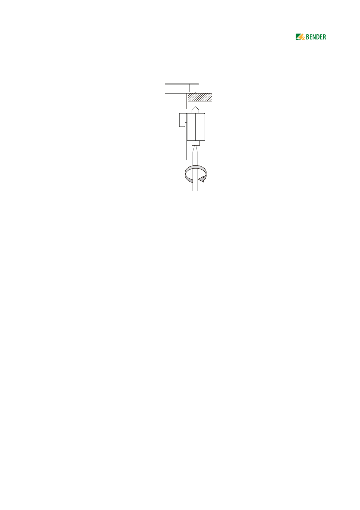
3. Fix the mounting brackets to the wall resp. to the sheet metal of the switchboard cabinet by
tightening the screws using a large flat-tip screwdriver. A tightening torque of approx. 0.5 Nm
is recommended.
CP700_D00005_02_M_XXEN/06.2014
19
Page 20
4.3 Connection of the device
15
910
234
678
4.3.1 Overview of the bus device interfaces
Installation, connection and commissioning
Key
Modbus/RTU interface. (cable included in the scope of delivery)
1
Switch for terminating resistor/bus bias voltage for Modbus/RTU interface.
2
BMS bus (Bender measuring device interface, cable included in the scope of delivery)
3
Switch for BMS bus termination/bus bias voltage.
4
USB interface, is not used
5
Connection to the supply voltage,
6
"see chapter "DC 24 V power supply" on page 21
Functional earth, see chapter "Earthing" on page 21
7
USB interfaces, are not used
8
Ethernet 10/100/1000, RJ45 socket for connection to a personal computer or to the local
9
network (hub, switch, router)
RS-232 interface, is not used
10
Details on the items 2 and 4:
"Terminating resistor/bus bias voltage" switch for Modbus/RTU interface:
Communication
mode
MASTER left activated on
Switch position
Terminating resistor/
bus bias voltage
LED
"Terminating resistor/bus bias voltage" switch for BMS interface.
Communication
mode
MASTER left activated on
Slave right deactivated off
Switch position
Terminating resistor/
bus bias voltage
20
LED
CP700_D00005_02_M_XXEN/06.2014
Page 21
Installation, connection and commissioning
1 2 3
CAUTION
4.3.2 DC 24 V power supply
The 3-pole plug required for the connection of the power supply is included in the scope of delivery.
The pin assignment is shown in the following table or is printed on the enclosure. The supply voltage
is internally protected by a permanently soldered fuse (10 A, fast-acting), so that in case of overload
(replacement of the fuse required) or wrong connection of the supply voltage the device will not be
damaged. If the fuse is damaged due to a fault, the device has to be returned to Bender for repair.
Pin Description
1 +
2 Functional earth
3-
Recommended power supply units:
Material
number/Type
0PS1025.2 B&R DC 24 V power supply unit, 2.5 A,
0PS1020.0 B&R DC 24 V power supply unit, 2 A,
1SVR427044R0200/
CP-D 24/2.5
EAN:
4016779661188
Manu-
facturer
DIN rail mounting/wall mounting
ABB Power supply unit
In: AC 100…240 V Out: DC 24 V/2.5 A,
Description
input AC 100…240 V,
WxHxD: 72 x 90 x 61 mm
input AC 100…240 V,
DIN rail mounting
WxHxD: 45 x 99 x 107 mm
DIN rail mounting
WxHxD: 71 x 91 x 57.5 mm
4.3.3 Earthing
Connect the functional earth (Pin 2) to the earth connection (e.g. switchboard
cabinet) using a cable as short as possible. Use the largest possible conductor
cross section that is permitted for the supply plug.
In addition, the earthing connection on the rear of the device has to be connected as follows.
CP700_D00005_02_M_XXEN/06.2014
21
Page 22
Installation, connection and commissioning
1
CP700
BMS
device
2
BMS
device
1
BMS
device
3
A2
A1
B2B1
15
69
BMS
BABA BA
CP700
RTU
device
2
RTU
device
1
RTU
device
3
A2
A1
B2B1
15
69
Modbus/RTU
D- D+D- D+ D- D+
BMS bus
Modbus/RTU
An earthing connection (1) is located at the rear of the CP700 for connection to a central earthing
point in the switchboard cabinet or the system where the device is to be installed. The largest possible wire cross section (minimum 2.5 mm²) should be used.
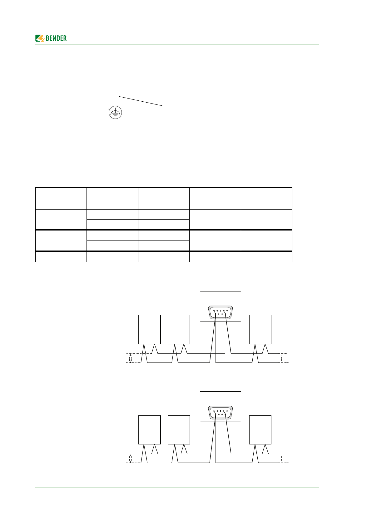
4.3.4 BMS bus, Modbus/RTU
Two connecting cables (RS-485 cable) are included in the scope of delivery. The double cable ends
facilitate the connection of the device if it is arranged in the middle of the bus. Both cables have the
same pin assignment.
Plug connector
Bridge 4--9
Bridge 1--6
Not connected shield black shield shield
Loose cable
ends
A1 white
A2 yellow
B1 brown
B2 green
Core colour
Connection to
the BMS bus
AD+
BD-
Connection to
Modbus
Wiring examples
22
CP700_D00005_02_M_XXEN/06.2014
Page 23

Installation, connection and commissioning
4.4 Commissioning
1. Switch the supply voltage on. - The "Settings" > "Interface" menu appears on the touch screen
(for details and factory settings refer to page 29).
Click on "Login" enter the settings.
2. Set the IP address.
If the connected computer network contains a DHCP server, activate the "DHCP" button. An IP
address is automatically assigned and displayed.
If the computer network does not include a DHCP server, the IP address, network mask (SN)
and standard gateway must be specified by the EDP administrator.
An IP address has been permanently assigned to the device. Therefore, deactivate the "DHCP"
button.
3. Set the BMS bus address for the CP700.
4. Set the baud rate and parity for the Modbus/RTU.
5. Set the display timeout. If no entry is made via the touchscreen of the CP700 for a predefined
time (e.g. five minutes), the screen is blanked.
The touch screen will be activated again when
– a new alarm occurs
– the number of alarms changes
– the screen is touched
6. Deactivate the "Show at startup" button. The "Settings" > "Interface" menu will no longer be
displayed during startup.
7. Confirm the changed settings with "OK". Tap on "Log out" when no more settings are to be
changed (not logged in).
CP700_D00005_02_M_XXEN/06.2014
23
Page 24

Installation, connection and commissioning
24
CP700_D00005_02_M_XXEN/06.2014
Page 25
5. Display and operating elements
1
2
7
6
5
4
3
11
10
9
8
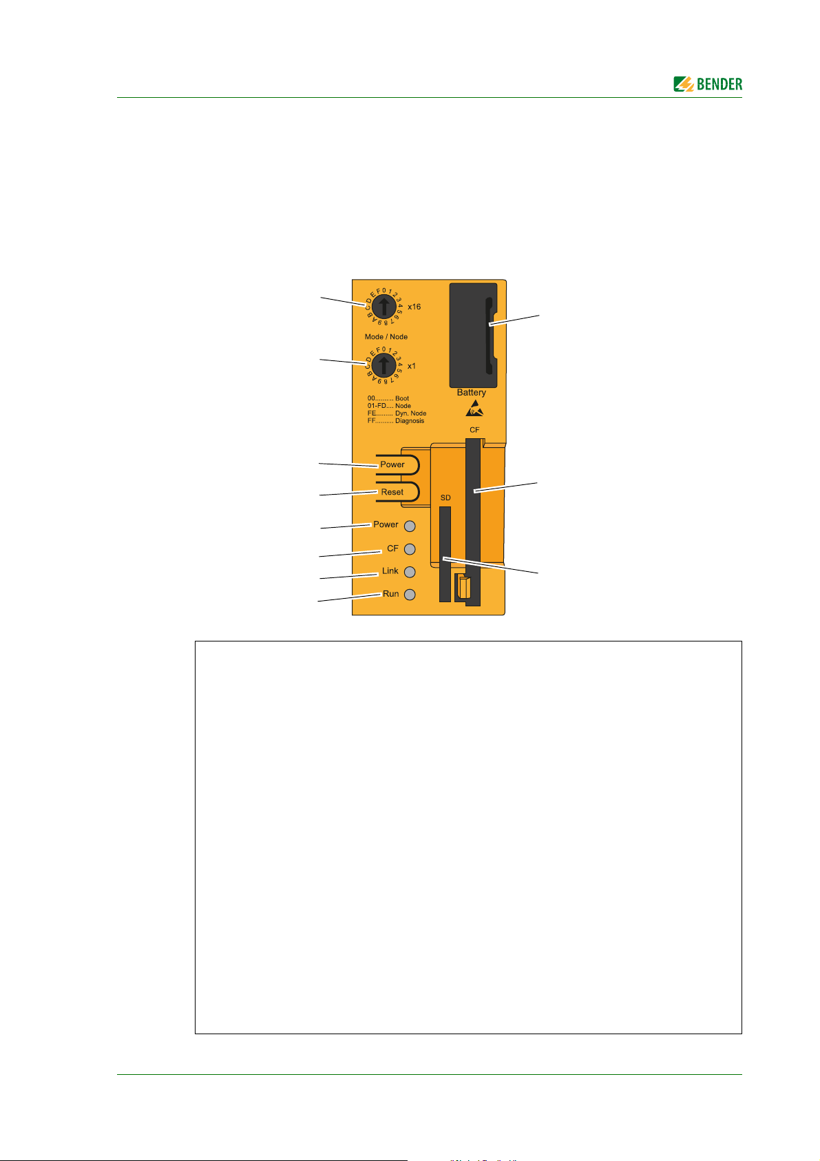
5.1 Operating elements at the rear of the device
Key
LED "Run"
1
LED "Link"
2
LED "CF"
3
LED "Power".
4
"Reset" button,
5
operation is not required. CP700 starts as soon as supply voltage is applied.
When the "Reset" button is pressed, a hardware reset will be initiated. The device restarts (cold
start). A system reset may result in data loss!
"Power" button“, operation not required. CP700 starts as soon as supply voltage is applied.
6
The function of the "Power" button is identical to that of a mains switch of current desktop personal computers:
Pressing the button for a short timewill switch the device on resp. will shut the operating system
down and switch the device off.
Pressing the button for a long timewill switch the device off without shutting down the operating system (Risk of data loss!)
"Mode/Node x16" switch, has no function
7
"Mode/Node x1" switch, has no function
8
SD memory card slot, has no function. Must not be used!
9
CompactFlash Slot. Must not be removed.
10
Battery, see chapter "Battery" on page 26
11
CP700_D00005_02_M_XXEN/06.2014
25
Page 26
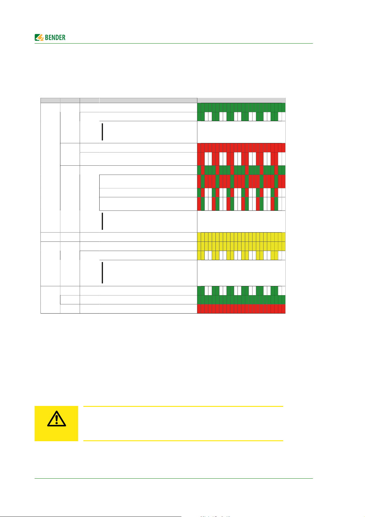
Display and operating elements
LED Color Status Meaning LED indicator
On Supply voltage OK
The device has booted, the battery status is "BAD".
Green
Blinking
Information:
For more information, see see " Battery" on page 33.
On The system is in standby mode (S5: soft-off mode or S4: hiber-
nate mode - suspend-to-disk)
Red
Blinking The MTCX is running, the battery status is "BAD". The system
is in standby mode (S5: soft-off mode or S4: hibernate mode suspend-to-disk)
Faulty or incomplete BIOS, MTCX or I/O FPGA update, battery
status OK, power supply OK
Faulty or incomplete BIOS, MTCX or I/O FPGA update, battery
status OK, standby mode (S5: soft-off mode or S4: hibernate
mode - suspend-to-disk)
Faulty or incomplete BIOS, MTCX or I/O FPGA update, battery
status BAD, power supply OK
Faulty or incomplete BIOS, MTCX or I/O FPGA update, battery
status BAD, standby mode (S5: soft-off mode or S4: hibernate
mode - suspend-to-disk)
Power
Red / green Blinking
Information:
An update must be performed again.
CF Yellow On Indicates IDE drive access (CF)
On Indicates an active SDL connection on the panel plug.
An active SDL connection has been interrupted by a loss of
power in the display unit.
Link Yellow
Blinking
Information:
Check the power supply / power connector of the
connected display unit.
Green Blinking Automation Runtime booting
Handled by Automation Runtime (ARemb and ARwin).
Green On Application running
Handled by Automation Runtime (ARemb and ARwin).
Run
Red On Application in service mode
Handled by Automation Runtime (ARemb and ARwin).
CAUTION
5.1.1 Status LEDs
For the status LEDs (Power, CF, Link, Run), the following time frame is being used:
Box width: 250 ms
Interval: 500 ms; Hence, 2 boxes correspond to one interval
5.1.2 Battery
The lithium battery (3 V, 950 mAh) buffers the internal real-time clock (RTC) and is located behind the
black cover. The duration of the battery is at least four years (at 50 °C, 8.5 μA current requirements of
the supplied components and a self-discharge of 40 %). The battery is subject to wear and should be
replaced regularly (at least following the specified life span) (see chapter "Battery change" on
page 165).
5.1.3 CompactFlash card
Do not remove the CompactFlash card in order to ensure that all device properties are available!
If a replacement of the CompactFlash card becomes necessary, you have to disconnect the device from the power supply.
26
CP700_D00005_02_M_XXEN/06.2014
Page 27

Display and operating elements
CAUTION
5.2 Touchscreen
Do not apply excessive force to the screen. Do not use a ballpoint pen, a pencil or
other sharp objects to operate the touch screen. This may damage or destroy the
touch screen.
The integrated 7 inch touch screen is used at the same time for indication and operation. This is a
resistive touch screen which responds to pressure.
For operation solely use finger or a touch pen. When sliding your finger over the display (e.g. when
scrolling through the language selection), apply the necessary pressure to the display.
CP700_D00005_02_M_XXEN/06.2014
27
Page 28

Display and operating elements
4
321
98756
5.3 Operation via touch screen
After the initial power-up, the CP700 enters the "Settings" > "Interface" menu. By tapping the " "
button you will access the main menu. If no entry has been made via the touch screen for several
minutes and the touch screen has switched to standby mode, the CP700 will automatically switch to
the main menu.
5.3.1 Main menu
The CP700 is equipped with a touch screen. That allows intuitive operation using your finger or a
special touch screen stylus.
Key
"Bus overview" button. Shows a list of the bus devices for selection, querying and parameterisa-
1
tion. BMS-bus device, Modbus/RTU devices, Modbus/TCP devices and virtual devices are displayed in the same list.
"Alarms" button. Shows a table of the pending alarms.
2
The background of the button
- is red when an alarm exists
- is white when no alarm exists.
"Settings" button. Allows the setting of the interface and the operation language of the device.
3
"Back" button. One operating step back.
4
5
" " button. Return to the main menu.
Device type or an individually entered text in the web user interface.
6
Date and time display.
7
Display "Logged in". Settings in the "Interface" menu can only be carried out after "Login". This
8
login applies to the operation of the touch screen only.
"Alarms" button. Shows a table of the pending alarms.
9
The same function as "2", but accessible from each submenu.
28
CP700_D00005_02_M_XXEN/06.2014
Page 29

Display and operating elements
5.3.2 "Settings" menu
Select:
Interface Interface parameter setting
Language Selection of the operation language for the CP700
5.3.2.1 "Interface" menu
Display settings
The existing settings will be displayed.
If you have not logged in, you cannot change the settings. Therefore the buttons for the setting values are not active (greyed out).
CP700_D00005_02_M_XXEN/06.2014
29
Page 30

Display and operating elements
Changing settings
The settings can only be changed in the "Logged in" mode. Tap on the "Login" button.
A password can be set in the "Bus overview > "Settings" > "Password" menu via the web user interface. The password consists of a 3-digit number. If a password has been set and activated (status
"on"), the following entry field will appear:
Enter the password. Then tap on "OK". The status "Logged in" is displayed.
If no password has been set, the status "logged in" will be displayed immediately.
Tap on the entry to be changed. An entry field appears. Enter the new value and Tap on "Close".
CP700 will check the settings:
identifies a permissible setting value
identifies an impermissible setting value or a setting value that makes no sense
30
CP700_D00005_02_M_XXEN/06.2014
Page 31

Display and operating elements
Parameter settings and factory settings
Factory setting Description
IP
SN
Standard
gateway
BMS
Modbus/RTU
DHCP
Display
timeout (min)
Show on
startup
192.168.0.254 Set the IP address of CP700
255.255.0.0 Set the subnet mask of CP700
192.168.0.1 Set the IP address of the gateway
2 Set the BMS address of CP700: 1…99 (internal BMS bus)
9600 Bd, even Modbus/RTU: Select baudrate and parity
Activate/deactivate automatic IP address assignment using the
DHCP server
1
If no entry is made via the touchscreen of the CP700 for a predefined time (e.g. five minutes), the screen is blanked.
Activate/deactivate the display of the "Settings" > "Interface"
menu when starting the device.
The CP700 can also be set via the web user interface (see "Parameter setting of
the CP700 using the "Settings" menu" on page 62).
5.3.2.2 "Language" menu
Select the preferred language by tapping on the respective button in the language column. Changes
take effect immediately.
The scroll bar on the right of the touch screen shows that more languages are
listed below. Move the presently displayed content upwards to display other languages.
CP700_D00005_02_M_XXEN/06.2014
31
Page 32

Display and operating elements
5.3.3 "Alarms" menu
Indication of alarm messages. Tap on "i" for a help text about this alarm.
5.3.4 "Bus overview" menu
The bus overview lists all devices connected to the CP700 as well as all virtual devices. Here, it does not
make a difference whether these devices are connected via BMS bus, Modbus/TCP or Modbus/RTU.
Address
,
Device name
Interface
Menu
32
Description
Device address
Indicates for this device: "No alarm" or "Alarm"
Device name. If previously entered in the web user interface, also an individual text will
be displayed.
Interface of the device that is used for communication with CP700, virtual device (VD)
Button to display all available menus of the device.
Example: Display alarm/meas. values and device info of the CP700.
The display is being updated. An update is performed every 3…5 seconds.
CP700_D00005_02_M_XXEN/06.2014
Page 33

Display and operating elements
5.3.5 Displaying the device info for CP700
Select "Bus overview" > "CP700 " > "Device info".
This menu displays information about the device and the software. Please have this information to
hand if you should need to contact us for assistance by telephone.
The scroll bar on the right of the touch screen shows that more information is
given below. Move the presently displayed content upwards to display the rest of
the information.
5.3.6 Using the functions for Bender PEM… universal measuring devices
Select "Bus overview" > "PEM575 " > "Device info". For a description of these functions refer to
chapter "Monitor for Power quality" on page 141.
CP700_D00005_02_M_XXEN/06.2014
33
Page 34

Display and operating elements
34
CP700_D00005_02_M_XXEN/06.2014
Page 35

6. Web user interface of the CP700
6.1 Menu structure of the web user interface
The table below provides an overview of the menus. The menus are easy to use by means of a browser. The listing is arranged according to the menu-bar shown below.
Menu bar Submenu: Description Page
Start
Bus overview
Alarms
Tools
Deutsch Indication and selection of the operating language 38
English
Other languages..
List of bus devices for
- Selection
- Query
- Parameter setting
Alarm window Presentation of all pending alarms and data of
BMS recording Manual recording of the BMS bus activity,
BMS analyser Evaluation of the BMS recording 83
BMS log files Selection and indication of the recorded BMS-log
Network parameters Displaying and changing network parameters* 86
Socket state Indication of the socket status in the browser win-
– Presentation of the bus structure with the exist-
ing interfaces (BMS, Modbus/RTU, Modbus/TCP)
– Colour coding of the bus devices according their
alarm or operating state
– Presentation of additional data of the bus device
selected via the "Device info" button
– Menu presentation of a selected bus device
– Parameter setting of the bus device selected
– Create, export or import a back-up/report includ-
ing all parameters of the respective device
– Enter individual texts for devices and channels
– Configure e-mail notification for alarm condition
– Activate/deactivate monitoring function for
device failure
– History memory and data logger
devices sending an alarm.
saving the record to a storage media outside the
CP700.
files in the browser window*
dow*
42
42
43
45
60
46
65
71, 74
77
50, 53
80
82
86
86
CP700_D00005_02_M_XXEN/06.2014
35
Page 36

Info
Visualisation
Web user interface of the CP700
Software update Update of the system software of CP700* 88
Software options Indication of the range of functions of the corre-
sponding option and the licensing of additional
options.
Modbus register Modbus register presentation of the connected
BMS devices and PEM... Bender universal measuring
devices
Modbus control commands Commands can be sent to BMS devices and Bender
PEM... universal measuring devices from an external
application (e.g. visualisation software). The "Modbus control commands" menu provides Modbus
control commands for selected BMS commands.
These commands can be copied to the clipboard of
the PC and then included in the programming for
external application.
Manage Modbus devices This function is used to make settings for Bender
devices of the PEM… series connected via Modbus/
RTU or Modbus/TCP and to save them in a template.
Individual texts Overview of all individual texts in the web user
interface pre-defined for devices and measuring
points (channels). Individual texts can be:
- exported to CSV format,
- processed externally (e.g. in Excel®)
- and imported.
Device failure monitoring Overview of all devices for which device failure
monitoring has been activated.
E-mail overview Overview of all devices and channels for which an
e-mail notification has been configured in the event
of an alarm.
E-mail configuration Setting e-mail templates: days of the week, time of
day, e-mail addressee and texts.
Visualisation Fast and simple visualisation without any program-
ming.
Manual Function, connection, operation etc.* 109
System visualisation Several gateways (COM460IP, CP700) on one web-
site. Displaying common alarms of the devices.
Manage virtual devices Set/modify/delete virtual devices 117
Software D405 V2.5x
Software D278 V2.5x
This menu displays information about the device
and the software. Please have this information to
hand if you need to contact us for assistance by tel-
ephone.
Carrying out visualisation 107
90
93
95
114
67
78
75
71
97
110
89
* Deactivate the pop-up-blocker function to use these functions, see chapter "6.2 ".
36
CP700_D00005_02_M_XXEN/06.2014
Page 37

Web user interface of the CP700
6.2 Browser configuration
The latest version of the Windows© Internet Explorer is recommended.
In order to fully benefit from all functions of the web user interface Silverlight
on the computer being used and Java Script has to be activated too. In addition, the pop-up blocker
has to be deactivated so that all functions are available to you.
Silverlight
JavaScript Should be activated; required for backup/report, software update etc.
Pop-up blocker Should be deactivated for the IP address of the CP700; otherwise there would be no
ActiveX Not required.
Microsoft Silverlight (version 5.0 or higher) must be installed.
access to the manual , software updates, network settings etc.
6.3 Initial operation of the web user interface:
1. Select the screen resolution as follows:
Width ≥ 1000 pixels, height ≥ 900 pixels, example: 1600 x 1200
2. Start the Internet browser
3. Read the IP address from the "Settings" > "Interface" menu using the touch screen and enter
the address into your Internet browser.
4. Select the user language for the web user interface. Click the language you want to use resp.
click the appropriate flag.
5. Click on "Bus overview" to get a graphical representation of all BMS bus devices. If everything
works properly, a list of all accessible BMS devices should appear after a few seconds. In the
most unfavourable case, it can take up to 7.5 minutes to list all the accessible devices on the
internal BMS bus (CP700 = MASTER).
If, nevertheless, malfunctions occur at the bus devices, please check if you use the current software
version for the respective device (also see "CP700-compatible devices" on page 14).
TM
has to be installed
CP700_D00005_02_M_XXEN/06.2014
37
Page 38

Web user interface of the CP700
6.4 Start page and operating language
6.4.1 Opening the start page
1. Open an Internet browser.
2. Enter the IP address of the CP700 into the address line (Example: http://162.18.22.18/). The
start screen will appear:
6.4.2 Changing the language
If a German Windows operating system is installed on the PC, the web user interface will start up in
German language.
1. Click " ".
2. Click the required language resp. on the typical national flag, to select the operating language
for the graphical user interface.
Fig. 6.1: Language selection
38
CP700_D00005_02_M_XXEN/06.2014
Page 39

Web user interface of the CP700
1342
6.5 Menu bar
The user interface can largely be controlled per mouse click.
Key
Menus and functions. Example: Start = select the menu language.
1
Input field for entering the password to log in. The edit filed won't appear unless a
2
"Login" password has been assigned in the password menu of the CP700 and the password protection has been activated before.
Button "Log in" resp. "Log out".
3
Logging in is the precondition for:
- the parameter setting of the recorded bus devices
- the settings of device failure monitoring, e-mail notification, individual texts and visualisation
Logging in ensures that only one user can change parameters at a given point of time.
For detailed information about parameter setting refer to page 60.
Common alarm indication. In the example illustrated above, two alarms exist. Click this
4
button to display the alarms (the same effect as menu item "Alarms").
CP700_D00005_02_M_XXEN/06.2014
39
Page 40

Web user interface of the CP700
DANGER
6.6 Bus overview and device information
6.6.1 Creating a password protection for CP700
Risk of damage to equipment due to unauthorized access
The password protection for the CP700 protects against unauthorised access to
a limited extent only. Attackers from the Internet may still be able to read data
and to change settings.
It is absolutely necessary
- that the network is separated from the Internet
- common security mechanisms are applied (firewall, VPN access)
The device allows a staggered password protection. The necessary settings are carried out via the
web user interface. Select "Bus overview" > "CP700" > "Load menu" resp. "Reload menu" > "Settings"
> "Password".
Protec-
Password
for
tion
ex
factory
Password
ex factory
Function of the password types
Character pool for passwords
Access to the "Settings" > "Interface" menu of
Device off 000
Server off default
Login off default
FTP off default
the CP700.
Login via the touch screen of the CP700
Password: 000…999
Access to the web server of the CP700 by logging on to the web server;
Password: a...z, 0...9, minus sign, underscore
Access to the parameterisation functions by logging on to the web user interface;
Password: a...z, 0...9, minus sign, underscore
Access to the FTP server of the CP700;
Password: a...z, 0...9, minus sign, underscore
If you log in with the password types "Server" and "FTP", you have to enter the
username "user" first!
Fig. 6.2: The standard user "user" logs on to the web server or FTP server with "default"
or by entering his password.
40
CP700_D00005_02_M_XXEN/06.2014
Page 41

Web user interface of the CP700
Example:
The parameterisation function of the CP700 is to be protected by a new password. According to the
table above, a login password has to be assigned. The password protection must also be activated!
1. Select "Bus overview" > "CP700" > "Load menu" resp. "Reload menu" > "Settings" > "Password"
> "Login".
In the first line, the appropriate edit field appears after which the maximum number of characters currently used is displayed. Double-click the current password and overwrite it with your
new password. After entering the first character, the colour of the edit field changes.
2. Click the button in the status line and select "on" in order to activate the password protection.
3. Press "Save". The result of the changes will appear in the "Parameterisation overview" window.
4. Click the "Log out" button in the menu bar.
As of now, parameter setting of the CP700 can only be carried out after logging in with the
new login password.
5. For logging on again, enter the password
CP700_D00005_02_M_XXEN/06.2014
Click "Login" prior to parameterisation even if password protection is deactivated! Logging in ensures that only one user can change parameters at a given
point of time.
41
Page 42

6.6.2 Buttons for the list of bus devices
CP700 on the internal BMS bus
3421 5
8
9
7
10
6
11
Web user interface of the CP700
Key
Button to open or close the list of bus devices and the device menu. Instead of using the
1
triangular buttons it is also possible to double-click or click the button of the bus device
resp. on the sub menus.
Alarm status of the device
2
Green Operating message
Red Alarm message
Grey Bus device has not responded for several minutes.
The grey symbol will only appear if the device failure monitoring function has
been activated before. As soon as the device failure monitoring function is
deactivated, the device will disappear from the list.
Internal BMS bus address
3
Type of BMS device
4
Click this button to open the device window indicating the measured values and alarms.
For details refer to chapter "6.6.4 Querying device information"
Indication of the CP700 the web server of which was used to set up a connection (font
5
"bold" and dark background)
Interface of the device that is used for communication with CP700:
6
B BMS bus
R Modbus/RTU
T Modbus/TCP
VD Virtual device
Number of alarms of this BMS device
7
Dark background identifies the selected bus device or menu item
8
Buttons for editing individual texts, configuring e-mails and activating device failure
9
monitoring function. You have to log in to activate the buttons. For details refer to
chapter "6.5 Menu bar"
Individual text "PQ Main Building"
10
11
+ Add Modbus devices or virtual devices.
Note: BMS devices are automatically recognised.
Close all opened menus of the bus overview
42
CP700_D00005_02_M_XXEN/06.2014
Page 43

Web user interface of the CP700
6.6.3 CP700 on the internal BMS bus
The device is operated on the internal bus. Only the internal addresses and bus devices are displayed.
6.6.4 Querying device information
1. Click on "Bus overview" in the menu bar to open the menu of the same name.
2. After uploading all devices, select the respective device from the list.
The device window will open displaying the measured values and alarms.
3. Enlarging and reducing the bus overview and device info: The display area can be enlarged to
the full width of the window by clicking on the "bus overview" resp. "device info" button.
Another click the button reduces the respective display area.
Presentation of basic data on the selected device:
No. Channel number resp. consecutive number of measured values resp. alarms
red
Ye l lo w
green
Alarm Possible alarm messages: "Alarm", "Fault", "Prewarning" or "Warning"
Te st "Internal test" or "External test"
Description Description of the alarm or operating message
Measured value Measured values transmitted from the bus
Alarm status of the channel
Red = alarm, warning, device error
Yellow = prewarning
Green = operating message
Additional data presented after clicking the "Device info" button:
Device type Example: isoMED427P
Last contact Last BMS-bus connection: Date and time
Number of alarms Number of alarms
External address
Internal address Internal BMS address
Activate "Hide inactive channels" to display active channels only.
CP700_D00005_02_M_XXEN/06.2014
External BMS address. will only be indicated when the CP700 is operated on the
external bus
43
Page 44

Web user interface of the CP700
6.6.5 Displaying the help text
If help texts exist, they will be marked by a blue "i" icon
1. Move the mouse pointer to the blue "i" icon in the "Measured value" column.
2. Keep the mouse pointer there (without clicking). - The help text will be displayed.
44
CP700_D00005_02_M_XXEN/06.2014
Page 45

Web user interface of the CP700
6.6.6 Loading the menu of a bus device
A PEM575 is used in the example below to illustrate the selection of a device menu
1. Start the browser and wait until the web
user interface appears.
2. Select the appropriate device: Click on ""
or double-click device type.
3. Click "Load menu".
The menu of the bus device is loaded completely. The menu presentation of the bus device in the
browser largely corresponds to the menu structure of the bus device in the device display.
6.6.7 Displaying the settings of a bus device
After loading the menu of the bus device, the "Settings" menu is available. In the example below, the
settings of an RCMS460-L are queried in the "General" menu.
1. Select "Settings": Click
"" or double-click
"Settings"
2. Click "General" 3. The settings of the "General"
menu item are listed
CP700_D00005_02_M_XXEN/06.2014
45
Page 46

Web user interface of the CP700
6.6.8 Creation and further processing of a bus device Back-up/Report
To store settings and measured values of a bus device, select the "Back-up/Report" menu item. In addition, the contents of the "Info" menu are recorded. The HTML file can be displayed and evaluated
using a standard browser. In order to display all the elements of a back-up file, JavaScript must be
activated. By creating a backup you can avoid data loss (e.g. by accidentally deleting settings). The
backup can also be imported to another device of the same type. This can be necessary when a device is to be replaced or when several devices with similar tasks are to be configured.
6.6.8.1 Creating a backup
1. Example CP700: Select "Bus overview" > "PEM575" > "Load menu" resp. "Reload menu" >
"Backup/Report“ > "Create backup".
2. Enter a text for backup identification.
3. Activate the appropriate check box "Device-specific settings":
Parameter Add the device settings to the backup.
Measured values Add the current measured values to the backup.
Comparison Load a stored backup to compare the parameters of an existing
backup with the parameters of a new backup to be created.
Click the "Next" button.
4. Activate the appropriate check boxes "System specific settings":
Activated system settings will be added to the backup.
Click the "Next" button. – Data is collected.
5. Click on "Complete". Confirm the subsequent security warning with OK. You can accept the file
name appearing in the subsequent window appearing or specify an individual name. After
storing the file the backup is completed.
46
CP700_D00005_02_M_XXEN/06.2014
Page 47

Web user interface of the CP700
6.6.8.2 Show the backup
1. Double-click the backup file in the storage location to open the file. As a result, the browser will
show a list field that corresponds to the device menu.
2. You can enlarge or reduce the individual menu items using the "+" and "-" buttons. Use "+All"
resp. "-All" to enlarge or reduce all menu items simultaneously.
3. Click the sub menu item you want to display. The associated parameters and its values will be
listed.
6.6.8.3 Creating a new backup with a comparison of the device parameters
1. Example RCMS460-L: Select "Bus overview" > "RCMS460-L" > "Load menu" resp. "Reload menu"
> "Backup/Report" > "Create backup".
2. Activate the respective selection box:
Parameter Add the device settings to the backup.
Measured values Add the current measured values to the backup.
Comparison Load a stored backup to compare the parameters of an existing back-
up with the parameters of a new backup to be created.
– Click the "Upload" button to load the previous backup to which the current parameters are
to be compared.
– Click the "Next" button. – Data is collected
3. Click on "Complete". Confirm the subsequent safety query with OK. You can accept the file
name appearing in the subsequent window appearing or specify an individual name. After
storing the file the backup is completed.
4. Double-click the backup in the storage location to open the file. In the new backup, the parameters and statuses to be compared are displayed side by side. Deviating measured values will
appear in red.
CP700_D00005_02_M_XXEN/06.2014
47
Page 48

Web user interface of the CP700
6.6.8.4 Using a backup for parameter setting
The parameter settings stored in a backup can be transferred to a bus device of the same type using
the function "Compare/Import".
On the one hand the backup file can be used to set the parameters of a bus device, on the other
hand, the parameters of a device used to replace an existing device can be set in a convenient manner.
PEM… only: If addresses are assigned twice, it is not possible to access the
device!
The backup files of PEM… also contain the address data of the original device.
After transmitting the backup file to another device, the address is also set in this
device. If two devices with the same address exist on the bus, it will be no longer
possible to access these devices via the web user interface. Correct the addresses
directly at the device.
1. Login to the menu bar.
2. Select "Bus overview" > "PEM575" > "Load menu" resp. "Reload menu" > „Backup/Report“ >
„Create backup".
3. Click the "Open backup" button to open the report file containing the parameter settings. Click
the "Next" button.
4. Activate the appropriate check box "Device-specific settings":
Parameter Add the device settings to the backup.
Measured values Add the current measured values to the backup.
Only activated settings will be transmitted from the backup file to the CP700
Click the "Next" button.
5. CP700 only: Activate the appropriate check boxes "System-specific settings": device failure
monitoring, e-Mail templates, individual texts, Modbus devices and templates, virtual devices.
Only activated settings will be transmitted from the backup file to the CP700.
Click the "Next" button.
6. The "Comparative overview" window will then open. By means of the "Excel" or "PDF" button.
The table can be exported for documentation purposes.
In the "Comparative overview" window only the differing parameter settings are displayed.
– Select the parameters to be transferred, by specifying the parameter individually or via the
respective check box.
48
CP700_D00005_02_M_XXEN/06.2014
Page 49

Web user interface of the CP700
– In case of longer lists, select via the "Select all" button or cancel the selection with the "Dese-
lect all" button or use the filter.
– Click on "Transfer selected values to device" to start the parameter transfer to the bus
devices. The "Parameterisation overview" window will show the process of transmission.
7. Click on "Complete". The backup has now successfully been loaded onto the device.
CP700_D00005_02_M_XXEN/06.2014
49
Page 50

Web user interface of the CP700
6.6.9 History memory
The history memory stores up to 1000 entries (prewarnings, alarms, tests) occurred on the BMS bus.
A maximum of 50 open alarm messages can be pending at the same time. The history memory can
be stored failsafe in the EEPROM.
If the history memory is full, the oldest entry will be deleted in each case in the event of an alarm, to
create space for the new entry.
6.6.9.1 Displaying the history memory
Select "Bus overview" > "CP700" > "Load menu" resp. "Reload menu" > "History". The history memory
will be displayed:
50
CP700_D00005_02_M_XXEN/06.2014
Page 51

Web user interface of the CP700
2
1
6.6.9.2 Evaluating the history memory
Sorting or filtering criteria saved in the history memory will be deleted after leaving the "History" menu.
Sorting entries
Click the column heading. Each time you click the column heading, you can choose whether you
want to sort in ascending or descending order.
Filtering entries
1. Move the mouse without clicking close to the required column heading.
2. Click the "" symbol.
3. Enter your own filter criteria (1) or activate/deactivate filter criteria proposed in the list (2).
You can link up to four filter criteria using "Or" resp. "And".
All entries of the history memory, including numerical values are treated like text by the filters.
4. Click the "Filter" button. The " " symbol will appear next to the column heading. The filter is
set.
It allows the setting of several filter criteria which are to be fulfilled at the same time. In addition, the
entries can be sorted.
Clearing filters
If a filter is no longer required, click the " " symbol and then on the "Clear" button.
Click on "Reset filters" to reset all filters
CP700_D00005_02_M_XXEN/06.2014
51
Page 52

Web user interface of the CP700
6.6.9.3 Exporting the history memory
The current representation of the history memory (if required, sorted and/or filtered) will be exported.
Excel
Pdf
Exports to an Excel file. That allows further processing of data.
Exports to a pdf file (e.g. forwarding by e-mail etc.).
6.6.9.4 Delete the history memory
1. Login to the menu bar.
2. Select "Bus overview" > "CP700" > "Load menu" resp. "Reload menu" > "Settings" > "History/
logger" > "History" > "1. Delete".
3. Click the "Delete" button. This entry must be confirmed once again.
Also refer to the description in table "History" on page 63.
6.6.9.5 Displaying the history memory of BMS devices
If a BMS device features a history memory, its entries can also be sorted and/or filtered as well as exported (Example: RCMS490-D).
52
CP700_D00005_02_M_XXEN/06.2014
Page 53

Web user interface of the CP700
6.6.10 Data logger
Up to 1000 entries can be recorded for each of the 12 data loggers.
6.6.10.1 Data logger setting
A new measured value will be saved when the conditions set in the "Bus overview" > "CP700" > "Load
menu" resp. "Reload menu" >"Settings" > "History/logger" > "Data logger" menu are fulfilled (refer
to the description of settings in the table "Data logger" on page 63). You also make settings for overwriting and deleting measured values here.
An existing data logger will be deleted when one of the settings "System", "Address" or "Channel" is changed.
6.6.10.2 Displaying the data logger
Select "Bus overview" > "CP700" > "Load menu" resp. "Reload menu" > "Data logger" > "Data logger..".
If measured values recently changed are not displayed, select "Load menu" resp.
"Reload menu".
CP700_D00005_02_M_XXEN/06.2014
53
Page 54

The selected data logger will be displayed:
2
3
1
Web user interface of the CP700
Overview of the graphical representation (Option D only).
1
Details of the graphical representation (Option D only).
2
Table view. Entries can be sorted and/or filtered as well as exported
3
Each of the three representations can be reduced by clicking the associated orange bar. This provides more space for other representations. Clicking the orange bar again will maximise the representation again.
6.6.10.3 Evaluating the data logger
All settings made for sorting or filtering the table view and settings for the graphical representation will be deleted as soon as the "Data logger..." menu is exited.
54
CP700_D00005_02_M_XXEN/06.2014
Page 55

Web user interface of the CP700
Using the overview
Determine the section to be zoomed in by moving the grey slider on the time axis to get a close-up
view of your document.
View details
In the "Details" mode you can zoom in the section to be viewed until the required zoom setting is
reached:
1. Click the beginning of the presentation to be viewed while holding down the mouse key.
2. Drag the mouse pointer to the end of the section to be viewed (dotted line) and
release it.
A close-up view of the selected section will appear immediately.
If you want to zoom in the current representation even more, repeat the previous procedure as
described in step 1 and 2.
Select "Zoom out" to restore the original representation.
CP700_D00005_02_M_XXEN/06.2014
55
Page 56

Web user interface of the CP700
2
1
Activate "Display limit lines" to display the limit lines (red) of the graphics. Enter the appropriate
limit values.
Sorting entries of the table view
Click the column heading. Each time you click the column heading, you can choose whether you
want to sort in ascending or descending order.
Filtering entries
1. Move the mouse without clicking close to the required column heading.
2. Click the "" symbol.
3. Enter your own filter criteria (1) or activate/deactivate filter criteria proposed in the list (2).
You can link up to four filter criteria using "Or" resp. "And".
4. Click the "Filter" button. The " " symbol will appear next to the column heading. The filter is
set.
It allows the setting of several filter criteria which are to be fulfilled at the same time. In addition, the
entries can be sorted.
56
CP700_D00005_02_M_XXEN/06.2014
Page 57

Web user interface of the CP700
Information on the use of the filter
Different filters are available for the entries of the data logger (numerical values, text, date/time).
Example: Text Example: Numerical values
Filtering numerical values reliably
Numerical values are treated as floating point values by the CP700 and are reduced to a meaningful representation. The "Equal to" therefore might not provide the appropriate numerical value. Use the filter criteria "Greater than" and
"Less than" to narrow down the numerical value.
Clearing filters
If a filter is no longer required, Click the " " symbol and then on the "Clear" button.
Click on "Reset filters" to reset all filters
CP700_D00005_02_M_XXEN/06.2014
57
Page 58

6.6.10.4 Apply the filter to the graphical representation
Click on "Update graph" to apply the filter to the graphical representation.
Web user interface of the CP700
6.6.10.5 Exporting the data logger
The current representation of the data logger (where applicable sorted and/or filtered) will be exported.
Excel Exports to an Excel file. That allows further processing of data.
Pdf Exports to a pdf file (e.g. forwarding by e-mail etc.).
58
CP700_D00005_02_M_XXEN/06.2014
Page 59

Web user interface of the CP700
6.6.10.6 Deleting the data logger
1. Login to the menu bar.
2. Select "Bus overview" > "CP700" > "Load menu" resp. "Reload menu" > "Settings" > "History/logger" > "Data logger".
3. Select one data logger or all data loggers (1…12).
4. Click the "9. Delete". This entry must be confirmed once again.
Also refer to the description in table "Data logger" on page 63.
6.6.10.7 Displaying the data logger of BMS devices
If a BMS device features a data logger its entries can also be sorted and/or filtered as well as exported
(Example: RCMS490-D).
CP700_D00005_02_M_XXEN/06.2014
59
Page 60

Web user interface of the CP700
CAUTION
6.7 Parameter setting for bus devices
The CP700 is compatible with Bender BMS devices and universal measuring devices PEM… (also see
"CP700-compatible devices" on page 14).
Incorrect parameter setting on bus devices may result in malfunctions! Therefore, the CP700 is to be protected by passwords against unauthorized access!
In the factory setting, password protection is deactivated. This facilitates the first
parameter setting during commissioning.
6.7.1 Operating elements for parameter setting
Edit field to change the values using the "" or
"
" buttons Slide the cursor over the edit field
to view the value range
Drop down list to select modes and functions.
Click the button to open the list
Corresponding function of the button
60
CP700_D00005_02_M_XXEN/06.2014
Page 61

Web user interface of the CP700
6.7.2 Setting the parameters for RCMS460-L
Click "Login" prior to parameterisation even if password protection is deactivated! Logging in ensures that only one user can change parameters at a given
point of time.
If a user has already logged on via the CP700, the next user will be informed about it.
Example:
The percentage prewarning level of the RCMS460-L is to be set to 55% of the alarm value.
1. Login to the menu bar for setting the parameters.
The "General" window will then show additional input fields.
2. Select "Bus overview" > "RCMS460-L" > Load menu" resp. "Reload menu" >"Settings" > "General".
3. Select "2. Prewarning", to increase the response value "" from 50 to 55%. The colour of the
edit field changes when a change has been made. The percentage prewarning threshold has
been changed.
4. Press "Save". The result of the changes will appear in the "Parameterisation overview" window.
Side effects displayed, displayed where appropriate, provide information about indirect
impact of parameter setting on other device functions.
5. Click the "Log out" button in the menu bar, if no other settings are to be changed.
Further parameter setting is only possible after logging on again.
CP700_D00005_02_M_XXEN/06.2014
61
Page 62

Web user interface of the CP700
6.7.3 Parameter setting of the CP700 using the "Settings" menu
If the device is incorrectly connected, parameter setting is not possible!
If the plug of the BMS connecting cable is not plugged in, the CP700 will not be
presented on the web user interface. Therefore, ensure that the BMS connecting
cable is connected to the CP700.
Once the CP700 is installed, parameterised via the device display and connected to the web server
of the gateway, additional settings or changes can be carried out comfortably using the browser. For
this purpose, the CP700 provides its own menu.
1. Login to the menu bar.
2. Select "Bus overview" > "CP700" > "Load menu" resp. "Reload menu" > "Settings".
Menu level 2 Menu level 3 Menu level 4 Factory
setting
Server
Interface
Modbus
Display
IP 1. IP 192.168.0.254 Set the IP address of the CP700
2. SN 255.255.0.0 Set the subnet mask of CP700
Standard
gateway
DHCP 1. DHCP on Activate/deactivate automatic IP address
1. Address 2
2. Interval 2 s Set the cycle time 1…3s for the sequence:
1. Control off Switch on or switch off the control via Mod-
2. Baud rate 9600 Select the baudrate for the Modbus
3. Parity even Select parity for the Modbus
1. Timeout 5 min If no entry is made via the touchscreen for a
1. IP 192.168.0.1 Set the IP address of the gateway
2. T(off) 30 s CP700 contacts the DHCP server for maxi-
Description
assignment using the DHCP server
mum 30s to obtain an IP address;
the communication time is adjustable in
steps of five seconds
for approx. 5...60s;
if no DHCP server can be reached, CP700 will
use the currently set IP address
Set the BMS address of CP700: 1…99
Setting has an effect on the internal bus
- Querying alarms in the BMS bus
- Querying new bus devices
- Offering the BMS master function
bus
predefined time, the touch screen will be
blanked (energy-saving mode). If the touch
screen of the CP700 is touched, it will switch
on again.
62
CP700_D00005_02_M_XXEN/06.2014
Page 63

Web user interface of the CP700
Menu level 2 Menu level 3 Menu level 4 Factory
setting
History/
History 1. Delete Delete the history memory. The entry must
Logger
Data logger Data logger 1 Click the "" symbol and select the data log-
1. Status off Activate or deactivate the data logger
Address and channel of the device to be monitored:
2. System 1 External BMS bus address
3. Address 2 Internal BMS bus address
4. Channel 1 Channel of the BMS device
A new entry will be saved when all three conditions (modification, trigger,
modification) are fulfilled (AND operator):
5.Modific. 2% A new measured value will be saved if it dif-
6. Trigger off A new entry will be saved after xx hours resp.
7. Modific off A new measured value is saved if it differs
8. Overwrite yes yes: If the memory is full (1000 entries per
9. Delete Delete data logger. The entry must be
Interface 1.Interface off Recording of the BMS-bus traffic, adjustable
Clock
1. Format d.m.y Date format
2. Date 01.01.2010 Date
3. Time 00:00 Time
4. CEST off Select Central European Summer Time:
5. NTP off Activate/deactivate the NTP server query for
6. IP 192.168.0.123 Set the IP address for the NTP server
7. UTC +1 Time zone setting (-12...+13):
Description
be confirmed once again.
ger to be set.
1, 2, … single data logger
1…12 all 12 data loggers
fers from the previous measured value by the
percentage value defined here.
7 days.
from the previous measured value by the
absolute value defined here.
data logger), the oldest entry will be
deleted to create space for the new
entry (ring buffer).
no: Data logger records 1000 measured
values then stops.
confirmed once again.
for 1...7 days or deactivation of the log function
off = Function switched off
DST = Automatic switchover, USA, CDN
CEST = Automat. switchover, Central Europe
on = set time zone + 1 h
time synchronisation;
UTC + 1h = CET
UTC + 2h = …
UTC + 3h = …
CP700_D00005_02_M_XXEN/06.2014
63
Page 64

Web user interface of the CP700
Menu level 2 Menu level 3 Menu level 4 Factory
Description
setting
Password
Device 1. Password 000 Enter/change password: 0…999
2. Status off Enable/disable password protection for
Parameter setting via the buttons of the
CP700
Server 1. Password default Enter/change password with a maximum of
10 characters: a...z, 0...9, minus sign, underscore
2. Status off Enable/disable password protection for
access to the CP700 web server
Login 1. Password default Enter/change password with a maximum of
10 characters: a...z, 0...9, minus sign, underscore
2. Status off Enable/disable password protection for the
Parameter setting via web user interface
FTP 1. Password default Enter/change password with a maximum of
10 characters: a...z, 0...9, minus sign, underscore
2. Status off Enable/disable password protection for FTP
access to CP700
The setting of the password protection is described on page 40, the parameter setting of a bus device by
the example of an RCMS460-D starting on page 60.
64
CP700_D00005_02_M_XXEN/06.2014
Page 65

Web user interface of the CP700
or
6.8 Entering individual texts
Individual texts allow unique identification of devices and measuring points (channels). The texts appear on the webuser interface, in exported files (backups) or in the visualisation.
Economising on texts in larger BMS systems!
If an individual text is assigned to each channel of a device, the limit of 1200 texts
can be reached in larger BMS systems. Therefore it is recommended to use texts
that apply to the whole device. These will be counted as one text entry, although
they are displayed for all device channels.
6.8.1 Enter individual texts for an RCMS460-L
Example: Individual texts are to be assigned to an RCMS460-L and to its channels.
1. Login to the menu bar.
2. Click the "Edit texts" field of the "RCMS460-L" bus device. This is optionally available in the bus
overview or in the device information.
CP700_D00005_02_M_XXEN/06.2014
65
Page 66

Web user interface of the CP700
3. Complete all fields which are to be applied for the whole "RCMS460-L" device. It is possible to
leave fields unused.
4. Proceed as follows to enter texts which are to be used for several channels:
– Click in turn the respective channels to open its input form. Clicking a channel again will
close the input form.
– In case of longer lists, use the "Open/close all" button
– Complete all fields which are intended for each of the selected channels. (Example: channel
3). It is possible to leave fields unused.
5. Press "Save". Modifications take effect immediately. The bus overview shows the RCMS460-L
and the associated text.
6. Click the "Log out" button in the menu bar, if no other settings are to be changed.
66
CP700_D00005_02_M_XXEN/06.2014
Page 67

Web user interface of the CP700
2
1
6.8.2 Displaying, filtering, exporting and importing individual texts
6.8.2.1 Displaying individual texts
1. Select "Tools" > "Configuration" > "Individual texts". The window "Individual texts" appears.
2. Click or double-click the column heading. The data will be sorted according to the column
heading in ascending or descending order.
6.8.2.2 Filtering entries
1. Move the mouse without clicking close to the required column heading.
2. Click the "" symbol.
3. Enter your own filter criteria (1) or activate/deactivate filter criteria proposed in the list (2).
CP700_D00005_02_M_XXEN/06.2014
67
Page 68

Web user interface of the CP700
4. Click the "Filter" button. The " " symbol will appear next to the column heading. The filter is
set.
5. It allows the setting of several filter criteria which are to be fulfilled at the same time. In addition, the entries can be sorted. If a filter is no longer required, Click the " " symbol and then
on the "Clear" button.
6.8.2.3 Exporting individual texts
Click on "Export" to export data in CSV format. The data can be externally displayed (e.g. in Excel®)
printed and edited.
68
CP700_D00005_02_M_XXEN/06.2014
Page 69

Web user interface of the CP700
23154
6.8.3 Editing and importing individual texts
Individual texts can be externally created in CSV format (character encoding: UTF-8), edited and imported to the CP700.
Evaluation is carried out line by line. The identification in the first line informs about the type of individual text. The lines can be in any order. The layout within the lines is as follows:
Key
Identifier allowing the CP700 to recognise what kind of individual text it is.
1
Other possible identifiers:
// Comment line
External BMS bus address
2
Internal BMS bus address
3
Channel number of the BMS device.
4
Channel number "0" means that this text applies to the whole device.
Individual text which will be assigned to the BMS device
5
Description of identification in column A
Identification in
column A
DeviceName Device name ... as name of the device
DeviceLost Device failure ... when the device has failed
DeviceFault Device error ... when the device signals a fault
DeviceWarning Alarm (for all channels) ... when one of the channels signals an alarm
DevicePreWarning Prewarning (for all
ChannelDescription Description channel ... as a description of an individual channel
ChannelWarning Warning/alarm chan-
ChannelPreWarning Prewarning channel ... when a prewarning is signalled by an individual
Plain text Individual text is being displayed..
... when a prewarning is signalled by one of the
channels)
nel
channels
... when an alarm is signalled by an individual channel
channel
CP700_D00005_02_M_XXEN/06.2014
69
Page 70

Web user interface of the CP700
If individual texts are to be assigned to many BMS devices, we recommend to proceed as follows:
1. Login to the menu bar.
2. Create individual texts for a BMS device on the web user interface (see chapter "7.7 Entering
individual texts")
3. Export these individual texts to a CSV file
4. Open the CSV file (e.g. using the Windows editor). Enter individual texts in the same way for all
other devices in the CSV file according.
5. Select "Tools" > "Configuration" > "Individual texts".
6. The window "Individual texts" will appear. Click "Import" and select the file to be imported.
7. After successful import, the message appears.
Click "OK"
8. Click the "Log out" button in the menu bar, if no other settings are to be changed.
Individual texts can also be set and assigned to devices not currently existing, if
device failure monitoring has been parameterised.
70
CP700_D00005_02_M_XXEN/06.2014
Page 71

Web user interface of the CP700
6.9 E-mail notification in the event of an alarm
CP700 allows e-mail notifications to be sent in the event of an alarm or system fault to different
gr oups of us ers. U p to five d ifferent templates can be set up. For using e-mail notifications, the CP700
must include Option A.
In just two steps e-mail notifications can be set up:
1. Create templates: To whom and when is an e-mail to be sent
2. Select devices and channels which are to trigger an e-mail notification
6.9.1 Create templates: To whom and when is an e-mail to be sent
A maximum of five templates can be created.
Example: A template for the weekend emergency service is to be created.
1. Login to the menu bar.
2. Select "Tools" > "Configuration" > "E-mail configuration".
3. Click " " to edit this template.
4. Enter the template name and the server settings.
The CP700 uses the e-mail server of the network in which it is located. Enter the IP address and
the port of the e-mail server. Enter the name of the user and the password for SMTP authentication.
CP700_D00005_02_M_XXEN/06.2014
71
Page 72

Web user interface of the CP700
5. E-mail settings
– Enter the sender address to be displayed.
– Enter the address the e-mail is to be sent to. Click "+" to add address fields.
– Enter subject, header and footer. There must not be umlauts in the subject line.
6. E-mail behaviour:
- Select days and hours that are to be applied for the template.
- Activate or deactivate "E-mail in the event of test alarm" resp. "E-mail in the event of prewarning" “.
7. Click "Save" to save the entries.
72
CP700_D00005_02_M_XXEN/06.2014
Page 73

Web user interface of the CP700
8. The list of configured templates will appear.
Click "Send test e-mail" to check the correct function of this e-mail notification. Other operating options:
- Click " " to delete this template
- Click " " to change this template
9. Open your e-mail post box to display the "Test e-mail".
10. Click the "Log out" button in the menu bar, if no other settings are to be changed.
CP700_D00005_02_M_XXEN/06.2014
73
Page 74

Web user interface of the CP700
or
6.9.2 Select devices and channels that are to trigger an e-mail notification
1. Login to the menu bar.
2. Click the "Configure e-mail" field of the "RCMS460-L" bus device. This is optionally available in
the bus overview or in the device information.
3. Assign the devices and channels that are to trigger an e-mail notification to the respective tem-
plates.
Click "Save" to save the entries. The blue symbol " " in the bus overview shows that e-mail
notifications for this device have been stored.
74
CP700_D00005_02_M_XXEN/06.2014
Page 75

Web user interface of the CP700
4. Repeat steps 2 and 3 for all devices assigned to the CP700.
You can also set up e-mail notifications for devices currently not available on the
bus if a device failure monitoring function has been configured for these devices.
5. Click the "Log out" button in the menu bar, if no other settings are to be changed.
6.9.3 Displaying an e-mail overview
Once the e-mail notifications are set up for all required devices, an overview can be displayed. Select
"Tools" > "Configuration" > "E-mail overview"
CP700_D00005_02_M_XXEN/06.2014
75
Page 76

Web user interface of the CP700
6.10 Using the device failure monitoring function
Devices assigned to the CP700 can be monitored for failure.
Behaviour when device failure monitoring is activated
If the device fails the "Alarm status" field in the bus overview is grey-shaded out.
Although the device is currently not available, it is treated as if it were available:
– An alarm will be signalled in the event of a device failure
– It will be displayed in the bus overview
– Individual texts can be entered
– E-mail notifications can be configured
– It can be visualised
Behaviour when device failure monitoring is deactivated
The device RCMS490-D will not be monitored for failure.
If the device RCMS490-D fails, it will disappear from the list. No alarm will be signalled.
76
CP700_D00005_02_M_XXEN/06.2014
Page 77

Web user interface of the CP700
or
6.10.1 Activating/deactivating device failure monitoring function in the bus overview
Activating device failure monitoring function
Example: The RCMS460-D is to be monitored for failure.
1. Login to the menu bar.
2. Click "Device failure monitoring on/off" of the bus device "RCMS460-D". This is optionally available in the bus overview or in the device information.
3. A message will confirm the activation of device failure monitoring.
In the bus overview the symbol " " shows that this device is monitored for failure.
4. Click the "Log out" button in the menu bar, if no other settings are to be changed.
Deactivating the device failure monitoring function
Example: The device failure monitoring function of the RCM460-L is to be deactivated
1. Login to the menu bar.
2. Click the "Device failure monitoring on/off" field of the bus device "RCMS460-L". This is optionally available in the bus overview or in the device information.
3. A message will confirm the deactivation of device failure monitoring.
4. Click the "Log out" button in the menu bar, if no other settings are to be changed.
Further parameter setting is only possible after logging on again.
CP700_D00005_02_M_XXEN/06.2014
77
Page 78

Web user interface of the CP700
6.10.2 Displaying overview device failure monitoring and adding devices
An overview of the devices monitored for failure will be displayed. Devices not yet connected to the
BMS bus can be added by entering the planned BMS address. For these devices individual texts can
be entered and e-mails can be configured. They can be visualised.
1. Login to the menu bar.
2. Select "Tools" > "Configuration" > "Device failure monitoring".
3. An overview of the devices monitored for failure will be displayed.
Monitoring all BMS devices
Select "Tools" > "Configuration" > "Device failure monitoring". Click "Import current state" and then
"Save" to monitor all active devices for failure which are currently connected to the BMS bus.
In the bus overview now all devices are now marked with the symbol " ".
78
CP700_D00005_02_M_XXEN/06.2014
Page 79

Web user interface of the CP700
Assigning a device to the CP700 that has not yet been connected
1. Select "Tools" > "Configuration" > "Device failure monitoring". Click "Add entry" to add a device
not yet connected.
2. Select the BMS address of the device and then click "OK".
Repeat step 2 for all devices to be added. Once all devices are added, click "Save". Although the devices are currently not available, they are treated as if they were available:
– An alarm will be signalled in the event of failure of these devices
– They will be displayed in the bus overview
– Individual texts can be entered
– E-mail notifications can be configured
– They can be visualised
CP700_D00005_02_M_XXEN/06.2014
79
Page 80

Web user interface of the CP700
6.11 Alarms
1. Click the common alarm button marked with an "!" or on the "Alarms" menu to open the window with the same name. Opening the window "Alarms" will deactivate the background.
Alarms can be sorted and filtered.
2. Close the alarm window by clicking on the "Close" symbol in the top right corner or press the
"ESC" button to return to the main menu.
The meaning of the table entries is described below.
No.
Address
Channel
red
Ye l lo w
Alarm
Te st
Device name
Description
Measured value
Timestamp
Consecutive number of alarms
Internal BMS address
BMS channel number
Red = alarm, warning, device error
Yellow = prewarning
Alarm, warning, prewarning, device error
Alarm caused by "Internal test"
Name of the BMS device
Description of the alarm or operating message
Measured values transmitted from the bus
Time and date the first alarm occurred
80
CP700_D00005_02_M_XXEN/06.2014
Page 81

Web user interface of the CP700
6.12 Tools
Select "Bus overview" > "Tools".
Display Menu Menu item Page
BMS Recording 82
Analyser 83
Log files 86
Network Parameters 86
Socket state 87
Software Update 88
Options 90
Modbus Register 93
Control commands 95
Manage devices 114
Configuration Individual texts 67,
96
Device failure monitoring 78,
96
E-mail overview 75,
96
E-mail configuration 71,
96
Visualisation 97
Other Manual 109
System visualisation 110
Manage virtual devices 117
CP700_D00005_02_M_XXEN/06.2014
81
Page 82

Web user interface of the CP700
6.12.1 BMS recording
You can record the current BMS bus traffic for control and analysing purposes and save it in a separate file on an external medium. For accessing and analysing recordings, use the BMS analyser.
1. Click "Tools" > "BMS" > "Recording". Recording will start immediately.
2. As soon as you consider the volume of the recording as sufficient, press the "Stop" button.
Recording is finished.
3. Now you have the choice to
– delete the recording
– save it on the PC or an external medium
– or to evaluate it using the BMS analyser
4. Click the respective button to carry out one of the activities listed above
In addition to the method described here, it is possible to record the BMS traffic (BMS logger) for a
period of 1…7 days.
Select "Bus overview" > "CP700" > "Load menu" resp. "Reload menu" > "Settings" > "History/logger"
> "Interface". Select the preferred duration by mouse click.
82
CP700_D00005_02_M_XXEN/06.2014
Page 83

Web user interface of the CP700
6.12.2 BMS analyser
With this tool, you can select the log file you need, open this file and analyse the recorded data of the
BMS bus using the different submenus.
The log files either are derived from the BMS logger previously activated in CP700 (CP700 >Settings
> History/Logger > Interface) or from the BMS recording. The recorded files of the BMS logger are
listed in the "Data source" submenu. Click the "Open external file" button to import the recorded
BMS data.
In the following example, data of the BMS logger are used.
Open recorded log files:
1. Click "Tools" > "BMS" > "Analyser".
2. Click the date of the desired file you need to open the "Statistics" data field.
3. In this data field, in particular, check the value "Protocol errors in %".
If the value is greater than 0, further analyses will be necessary. The "Errors" submenu may be
helpful in this case.
BMS analysis, statistics
CP700_D00005_02_M_XXEN/06.2014
83
Page 84

Web user interface of the CP700
BMS analysis, error
In the "Errors" list field, bus faults and special bus activities are listed. Faults appearing in the right
protocol field are marked in red, bus activities by contrast are marked in grey.
1. Click the first line of the list in the "Errors" list field. As a result, the first faulty line in the right
protocol field will appear red marked.
2. Proceed accordingly with the next and the other lines in the "Errors" list field. The selected line
of the protocol field will be highlighted.
BMS analysis, answers
In the "Answers" list field, the master-slave behaviour relating to the BMS addresses of the bus devices is shown in detail. The column "Unrequested", for example, shows whether a certain bus device
has answered without having received a request.
1. Click the "Answer" tab“, to open the list field of the same name and to get information about
the answering behaviour of the recorded bus devices.
84
CP700_D00005_02_M_XXEN/06.2014
Page 85

Web user interface of the CP700
BMS analysis, timestamp
Every minute, timestamps are added to the BMS data flow.
In the "Timestamps" list field, the timestamps added and the associated line numbers are put into
context. In addition, you can see how many lines have been recorded between two timestamps. This
information may be useful for the analysis of bus faults.
1. Click the "Timestamps" tab. The timestamps will appear in the list box in chronological order.
2. Click on one of the other timestamps in the list field on the left. In parallel, the associated
timestamp of the recorded BMS traffic will be highlighted in the protocol field.
CP700_D00005_02_M_XXEN/06.2014
85
Page 86

Web user interface of the CP700
CAUTION
6.12.3 BMS Log files
Use this menu item to view the complete text of the log file in a browser window.
Start recording
Select "Bus overview" > "CP700" > "Load menu" resp. "Reload menu" > "Settings" > "History/logger"
and specify the number of days you want to record.
Display recording
1. Click "Tools" > "BMS" > "Log files". The list of all log files that are automatically recorded will
appear in a browser window.
2. Click the required log file in the "File name" column. The recorded BMS lines appear in text format in a separate window.
6.12.4 Network parameters
You can change the network parameters of the CP700 in this menu.
Only change parameters after careful planning!
Incorrect settings may lead to serious disturbances in the network!
The following parameters can be set:
IP address
Netmask
Standard gateway
DHCP activated/deactivated
86
CP700_D00005_02_M_XXEN/06.2014
Page 87

Web user interface of the CP700
Proceed as follows:
1. Select "Tools" > „"Network" > "Parameter". The window "Network parameters" will appear.
2. Carry out your modifications and enter them into the input fields intended for this purpose
and confirm with "Change".
If you do not want the entries to be saved, select "Undo" to maintain the previous value.
6.12.5 Socket state
The current socket parameters appear in this list field. It allows to check the client/server connections.
1. Select "Tools" > "Network" > "Socket status". The current state of all sockets appears in a
browser window.
2. Click on "Refresh", if you want to update the list of connections.
CP700_D00005_02_M_XXEN/06.2014
87
Page 88

Web user interface of the CP700
6.12.6 Software update
You can update the operating software for CP700 as soon as Bender makes a new software version
available.
The "Software Update" menu allows you to comfortably:
load the update file from your computer to the CompactFlash card of the CP700
start the operating software update
Proceed as follows:
Adjust the browser settings
1. Make sure that JavaScript is activated.
2. Deactivate the pop-up blocker for the duration of the update process.
Open the "Software Update" window
1. Select "Tools" > "Software" > "Update"
2. Find out which software version is installed, e.g.: 2.xx.
Loading the current update file from the Bender Internet server
1. Click on "Bender download area" in the "Software update" window.
Alternatively you can also enter the address
http://www.bender-de.com/en/service-support/download.html
into the address line of your web browser.
2. Load the update file CP700 Vx.xx.BUF from the category software.
The category software will be visible as soon as the login procedure has elapsed.
3. Click the respective icon in the software list and specify a place Icon and specify a place to save
the update when you are prompted to do so.
Uploading the update file to the CP700
1. Click on "Browse" in the "Software update" menu to select the loaded update file. In the window "Software update" the respective path will appear.
2. Click on "Upload" to copy the update file CP700 Vx.xx.BUF to CP700. Once the file transfer
is completed the file path is blanked out.
Starting the software update
1. Click on "Start update" to start the update of the system files.
The progress bar in the "Software update" window will tell you when transmission is complete.
2. An activity indicator and the lettering "UPDATE" will appear in the display of the CP700.
Once the update is completed, after approximately 10 minutes, the device can be operated
again.
During the software update, the following directories are deleted and renamed:
\DEVICES
\IMAGES
\JS
\BIN
\HELP
\MISC
\LANG
88
CP700_D00005_02_M_XXEN/06.2014
Page 89

Web user interface of the CP700
Select language:
.
Testing the status of the updated software
1. Select "Info" from the menu bar to open the window of the same title.
2. If the software has been updated correctly, the numbers of the software versions will be
identical.
If the number of the version in the upper line is higher than the number in the line below, the browser cache should be cleared and the request for the software version should be repeated.
CP700_D00005_02_M_XXEN/06.2014
89
Page 90

Web user interface of the CP700
6.12.7 Software options and licensing
6.12.7.1 Identifying activated software options
Click the menu item "Software options" to make the currently enabled options visible. In line "Activated" in the "Software options" window, currently activated options are indicated with a green
check mark, options that are not activated are marked with a red X.
In the standard version of the CP700, all software options are already activated.
Proceed as follows to identify activated options:
1. Select "Tools" > "Software" > "Options".
2. Line "Activated" shows the activated options.
Fig. 6.3: The software options A, B, C and D are activated
When not all software options are activated, other options can be acquired and can be imported using a license file.
90
CP700_D00005_02_M_XXEN/06.2014
Page 91

Web user interface of the CP700
6.12.7.2 Acquiring licences for additional software options and loading the licence file
Once a licence is acquired from our sales department for one or several software options, the corresponding licence *.BLF will be available under the address
http://www.bender-de.com/en/licences.html
As soon as the login procedure has been passed successfully, the website "licences" appears. Follow
the user guidance there.
1. Enter the groups of numbers, which are printed on the device label or on the enclosure or are
available in the Info menu of the CP700, into the edit fields "Artikel-Nr./Art. no" and Werk-Nr./
Serial no".
2. Then click on "Get licence file". A green text field will appear showing the name of your new
licence.
3. Right-click to open the context menu and click on „Target save as”. There, you select the memory location and confirm with OK.
Fig. 6.4: Enter the article number and serial number into the licence window
Fig. 6.5: The licence file was generated and must be saved
CP700_D00005_02_M_XXEN/06.2014
91
Page 92

Web user interface of the CP700
6.12.7.3 Activate acquired software options
The license file *.BLF loaded from the Bender server has to be imported to the CP700 in order to
activate additional software options.
1. Select "Tools" > "Software" > "Options".
2. Click on "Import" to open the file list that contains the loaded licence file of the format *.BLF.
3. Select the required file and confirm with "Open".
All available options will then be confirmed by a green check mark in the line "Activated" of the
"Software options" window.
92
CP700_D00005_02_M_XXEN/06.2014
Page 93

Web user interface of the CP700
6.12.8 Modbus register
Also refer to the chapters "Manage Modbus devices" on page 114, "Data access using the Modbus/
TCP protocol" on page 121 and "Process image in the memory of the CP700" on page 123.
Display Modbus functions and their register addresses
Sections of the memory image of a BMS device can be represented graphically using the "Modbus
register" menu. 12 BMS channels can be displayed individually or details about the device. Up to 30
channels can be displayed on universal measuring devices PEM….
A detailed description of the Modbus data structure can be found on page 121 onwards.
6.12.8.1 Modbus representation of device information
In the example below details about an RCMS460 device with BMS address 18 is shown.
1. Select "Tools" > "Modbus" > "Modbus register".
2. First click on RCMS460-D in the device list and then select "Device info" from the drop down list
next to it. The Modbus representation of the device information and the corresponding start
addresses will appear.
In the column furthest to the right, the hexadecimal start addresses of the respective information
blocks are listed:
Start address 0x1200 = BMS address 18, device type
Start address 0x120A = BMS address 18, timestamp
Start address 0x120E = BMS address 18, common alarm and device error
CP700_D00005_02_M_XXEN/06.2014
Fig. 6.6: Modbus representation of device information
A real BMS device cannot have address 0!
Address 000/TEST only serves to simulate data access
(see "Reference data records of the process image" on page 131).
93
Page 94

Web user interface of the CP700
6.12.8.2 Modbus representation of a BMS channel
In the following example, the BMS channel 1 of an RCMS460 with BMS address is shown.
1. Select "Tools" > "Modbus" > "Modbus register".
2. First click on RCMS460-D in the device list and then select "Channel 1" from the drop down list
next to it. The Modbus representation of BMS channel 1 with the respective start addresses will
appear.
In the column furthest to the right, the hexadecimal start addresses of the selected BMS channel are
shown. These addresses represent the beginning of the related information blocks in each case:
Start address 0x1210 = BMS address 18, channel 1, floating point value (Value (Float))
Start address 0x1212 = BMS address 18, channel 1, alarm type and type of test as well as range &
unit
Start address 0x1213 = BMS address 18, channel 1, description
Fig. 6.7: Selection of the BMS device and of an BMS channel
Fig. 6.8: Modbus representation of the BMS address and BMS channel 1
94
CP700_D00005_02_M_XXEN/06.2014
Page 95

Web user interface of the CP700
6.12.9 Modbus control commands for BMS devices
From an external application (e.g. visualisation software) commands can be sent to BMS devices. This
menu item provides the Modbus control commands for selected BMS commands.
The control function via Modbus can be activated in the "Settings" > 3. Modbus > 1. Control" menu.
(see chapter "6.7.3 ").
Control commands for the internal BMS bus
– Test Isometer
– Test changeover device PRC, ATICS
– Start automatic test changeover 1->2, end after T(test)
– Start Test generator without changing over
– Changeover to line 1
– Changeover to line 2
– RESET alarm (broadcast)
– RESET alarm EDS (broadcast)
– Buzzer off [for alarm address] (broadcast)
– Switch on relay/switch
– Switch off relay/switch
These control commands can be copied to the clipboard of the PC and then included in the programming for external application. The menu item "Modbus control commands" therefore serves as
a programming aid.
1. Select "Tools" > "Modbus" > "Control commands".
2. Select the address of the device from the list the command is to be sent to. The list shows all
devices available on the BMS bus as well as devices which are currently not available, for which
a "device failure monitoring" function is set up.
CP700_D00005_02_M_XXEN/06.2014
95
Page 96

Web user interface of the CP700
3. Select the command you intend to send to the device from the list "BMS command". Commands marked with "Broadcast" apply to all BMS devices.
The Modbus commands and the associated explanations will be displayed.
4. Click "To the clipboard“. This command can now be included into the programming of an
external application (e.g. visualisation software).
6.12.10 Individual texts, device failure monitoring, e-mail configuration
The following functions are described elsewhere within this operating manual:
Menu item Description Page
Individual texts Overview of all individual texts in the web user interface
pre-defined for devices and measuring points (channels).
Individual texts can be:
- exported to CSV format,
- edited externally (e.g. in Windows® editor)
- and can be imported.
Device failure monitoring Overview of all devices for which device failure monitoring
has been activated.
E-mail overview Overview of all devices and channels for which an e-mail
notification has been configured in the event of an alarm.
E-mail configuration Setting e-mail templates: days of the week, time of day, e-
mail addressee and texts.
67
78
75
71
96
CP700_D00005_02_M_XXEN/06.2014
Page 97

Web user interface of the CP700
132 4
6.13 Visualisation
Fast and simple visualisation without any programming. For example, measured values and alarm
statuses of devices and channels can be arranged on a floor plan and can be displayed.
Displaying an overview the contents of which takes up more than one page. Jump to another view
page and back to the overview page.
6.13.1 Create visualisation
1. Login to the menu bar.
2. Select "Tools" > "Configuration" > "Visualisation".
Key
Tools for configuration:
1
- Add view Creating a new view page
- Add link Add a jump to another view page
- Add text Add a text line with max. 100 characters
- Add data logger Add a data logger. A maximum of 12 data loggers can be
BMS bus devices and channels
2
Insert the selected device or channel into the displayed view page by clicking "+".
CP700_D00005_02_M_XXEN/06.2014
inserted in one view page.
97
Page 98

Web user interface of the CP700
Key
Options:
3
- Save configuration Saves the current configuration to the CP700's micro-SD
card.
- Export Exports the current configuration to a file on the PC (e.g. as
backup copy)
- Import Imports the configuration file saved on the PC to the CP700.
Visualisation view
4
Up to 20 view pages can be displayed.
Clicking on the "Options" button will reduce the display area to provide more
space for the visualisation view.
Use "Save configuration" to save the visualisation configuration on the CompactFlash card in the CP700 (see "Save and exit configuration" on page 106).
You can save the visualisation to a file on the PC by clicking "Export", even after
only a fraction of the configuration file has been loaded (see "Export configuration" on page 106). In this way, you can avoid data loss (e.g. unintentionally deleting a page).
You can also carry out settings for visualisation for devices currently not
available on the bus if a device failure monitoring function has been configured
for this device.
98
CP700_D00005_02_M_XXEN/06.2014
Page 99

Web user interface of the CP700
6.13.1.1 Creating a new view page
Add view
3. Select "Add view". Enter a name for this
A new view page with the name "Start" will appear. The "Properties" button provides the fol-
lowing functions:
– Name Changing the name of the view page.
– Load image Adds a new background image. Existing back ground images will
– Delete element Deletes this view page.
view page (e.g. "Start") and click "OK".
be replaced.
Loading a background image
4. Have a picture at hand in png or jpg format. Click "load image". Select the image file and click
"Open". The image will be displayed immediately.
Images with clear contours and few colours produce a clear image. In case of
coloured and complex images, CP700 optimises memory requirement in order to
avoid blurred images.
CP700_D00005_02_M_XXEN/06.2014
99
Page 100

Web user interface of the CP700
Adding additional view pages
5. Repeat the steps 4 and 5 to add additional view pages. Example: "Circuit diagram" and "Plan
view".
100
CP700_D00005_02_M_XXEN/06.2014
 Loading...