

Page 1
Manual
EN
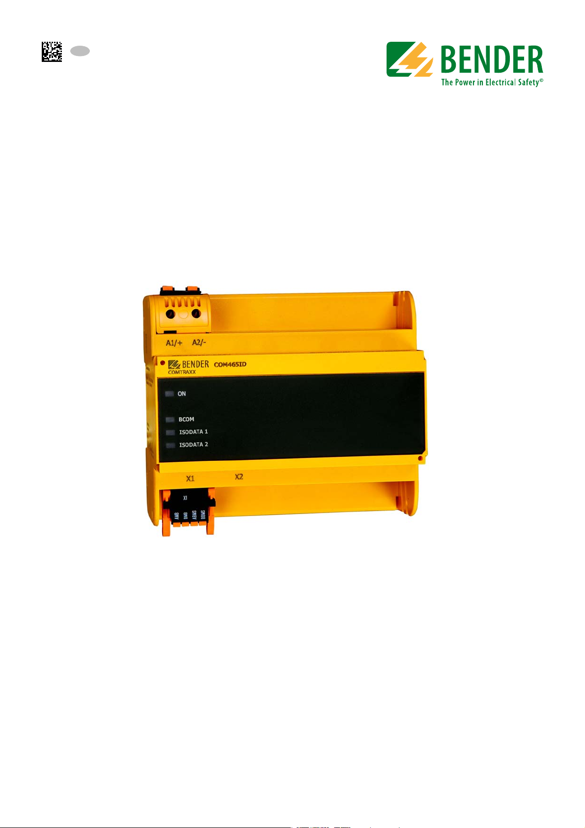
COMTRAXX® COM465ID
Condition Monitor with integrated gateway
for the connection of Bender isoData devices
with Ethernet TCP/IP networks
Software version: D472 V3.xx
COM465ID_D00368_01_M_XXEN/05.2019
Page 2

Bender GmbH & Co. KG
P.O. Box 1161 • 35301 Gruenberg • Germany
Londorfer Strasse 65 • 35305 Gruenberg • Germany
Tel.: +49 6401 807-0 • Fax: +49 6401 807-259
E-mail: info@bender.de • www.bender.de
Photos: Bender archive.
© Bender GmbH & Co. KG
All rights reserved.
Reprinting only with permission
of the publisher.
Subject to change!
Page 3

Table of Contents
1. General instructions ............................................................................................... 5
1.1 How to use this manual ......................................................................................................... 5
1.2 Technical support: service and support ........................................................................... 6
1.2.1 Consultation ........................................................................................................................ 6
1.2.2 Repair ..................................................................................................................................... 6
1.2.3 Customer service ............................................................................................................... 6
1.3 Training courses ....................................................................................................................... 6
1.4 Delivery conditions ................................................................................................................. 7
1.5 Inspection, transport and storage ..................................................................................... 7
1.6 Warranty and liability ............................................................................................................. 7
1.7 Disposal ....................................................................................................................................... 7
2. Safety instructions .................................................................................................. 8
2.1 General safety instructions ................................................................................................... 8
2.2 Work activities on electrical installations ........................................................................ 8
2.3 Intended use .............................................................................................................................. 8
3. Product description ................................................................................................ 9
3.1 Scope of delivery ...................................................................................................................... 9
3.2 Device features ......................................................................................................................... 9
3.2.1 Range of functions COM465ID (basic device without function modules) ... 9
3.2.2 Function module A ........................................................................................................ 10
3.2.3 Function module B ........................................................................................................ 10
3.2.4 Function module C ........................................................................................................ 10
3.2.5 Function module D* ...................................................................................................... 10
3.2.6 Function module E ........................................................................................................ 10
3.2.7 Function module F ........................................................................................................ 10
3.3 Applications ............................................................................................................................ 11
3.3.1 Interfaces ........................................................................................................................... 11
3.4 Function ................................................................................................................................... 11
3.4.1 Absence of interaction ................................................................................................. 11
4. COM465ID installation ........................................................................................ 12
4.1 Preparation .............................................................................................................................. 12
4.2 Installation ............................................................................................................................... 13
COM465ID_D00368_01_M_XXEN/05.2019
3
Page 4

5. COM465ID connection ........................................................................................ 14
5.1 Connections ........................................................................................................................... 14
5.1.1 Wiring diagrams .............................................................................................................. 15
5.1.2 Termination of the isoData interface ...................................................................... 16
5.2 Display and operating elements ..................................................................................... 16
5.3 COMTRAXX® user interface of the COM465… ............................................................ 17
5.4 Changing parameters ..........................................................................................................18
6. Commissioning of the COM465ID ..................................................................... 19
7. Troubleshooting ................................................................................................... 23
7.1 Malfunctions ........................................................................................................................... 23
7.1.1 What should be checked? ........................................................................................... 23
7.1.2 Frequently asked questions ....................................................................................... 23
7.2 Maintenance ........................................................................................................................... 23
7.3 Cleaning .................................................................................................................................... 23
8. Technical data ....................................................................................................... 24
8.1 Tabular data ............................................................................................................................ 24
8.2 Standards, approvals and certifications ........................................................................ 26
8.3 Ordering details ..................................................................................................................... 26
Table of Contents
INDEX ...........................................................................................................................27
4
COM465ID_D00368_01_M_XXEN/05.2019
Page 5
1. General instructions
1.1 How to use this manual
This manual is intended for qualified personnel working in electrical engineering and electronics.
This manual describes the gateway COMTRAXX® COM465ID. Before using the device, please read:
This manual. It describes the function, installation and commissioning of the device as well as the appli-
cation using the interfaces isoData and OPC UA.
The "COMTRAXX" manual for the functions of the COMTRAXX® user interface.
The supplement "Important safety instructions for Bender products".
The manuals for the system components.
If the respective interface is used, please read:
The "BCOM" manual. It describes the new Bender interface.
COMTRAXX® COM465ID is also referred to in this manual as "COM465ID" for short.
COMTRAXX® is a registered trademark of Bender GmbH & Co. KG.
Always keep this manual within easy reach for future reference.
We have used symbols to identify important instructions and information:
This signal word indicates that there is a high risk of danger, that will result in
death or serious injury if not avoided.
This signal word indicates a medium risk of danger that can lead to death or se-
rious injury, if not avoided.
This signal word indicates a low-level risk that can result in minor or moderate
injury or damage to property if not avoided.
This symbol refers to information that is designed to help you make the best use
of the product.
COM465ID_D00368_01_M_XXEN/05.2019
5
Page 6

General instructions
1.2 Technical support: service and support
For commissioning and troubleshooting Bender offers:
1.2.1 Consultation
Technical support by phone or e-mail for all Bender products
Questions about specific customer applications
Commissioning
Troubleshooting
Telephone: +49 6401 807-760*
Fax: +49 6401 807-259 In Germany only: 0700BenderHelp (telephone and fax)
E-mail: support@bender-service.de
1.2.2 Repair
Repair, calibration, update and replacement service for Bender products
Repair, calibration, testing and analysis of Bender products
Hardware and software update for Bender devices
Delivery of replacement devices for faulty or incorrectly delivered Bender devices
Extended warranty for Bender devices with in-house repair service or replacement device at no extra
cost
Telephone: +49 6401 807-780** (technical issues)/
+49 6401 807-784**, -785** (commercial issues)
Fax: +49 6401 807-789
E-mail: repair@bender-service.de
Please send the devices for repair to the following address:
Bender GmbH, Repair Service,
Londorfer Str. 65,
35305 Gruenberg
1.2.3 Customer service
On-site service for all Bender products
Commissioning, parameter setting, maintenance, troubleshooting for Bender products
Analysis of the electrical installation in the building (power quality test, EMC test, thermography)
Practical training courses for customers
Telephone: +49 6401 807-752**, -762 ** (technical issues)/
+49 6401 807-753** (commercial issues)
Fax: +49 6401 807-759
E-mail: fieldservice@bender-service.de
Internet: www.bender.de
*Available from 7.00 a.m. to 8.00 p.m. on 365 days of the year (CET/UTC +1)
**Mo-Thu 7.00 a.m. - 4.00 p.m., Fr 7.00 a.m. - 1.00 p.m.
1.3 Training courses
Bender is happy to provide training regarding the use of test equipment. The dates of training courses and
workshops can be found on the Internet at www.bender.de -> Know-how -> Seminars.
6
COM465ID_D00368_01_M_XXEN/05.2019
Page 7

General instructions
1.4 Delivery conditions
The conditions of sale and delivery set out by Bender apply.
For software products, the "Softwareklausel zur Überlassung von Standard- Software als Teil von Lieferungen,
Ergänzung und Änderung der Allgemeinen Lieferbedingungen für Erzeugnisse und Leistungen der Elektroindustrie" (software clause in respect of the licensing of standard software as part of deliveries, modifications and
changes to general delivery conditions for products and services in the electrical industry) set out by the ZVEI
(Zentralverband Elektrotechnik- und Elektronikindustrie e.V., (German Electrical and Electronic Manufacturers'
Association) also applies.
Conditions of sale and delivery can be obtained from Bender in printed or electronic format.
1.5 Inspection, transport and storage
Inspect the dispatch and equipment packaging for damage, and compare the contents of the package with the
delivery documents. In the event of damage in transit, please contact Bender immediately.
The devices must only be stored in areas where it is protected from dust, humidity and spray or dripping water,
and in which the specified storage temperatures can be assured.
1.6 Warranty and liability
Warranty and liability claims in the event of injury to persons or damage to property are excluded if they can
be attributed to one or more of the following causes:
Improper use of the device.
Incorrect mounting, commissioning, operation and maintenance of the device.
Failure to observe the instructions in this operating manual regarding transport, commissioning, oper-
ation and maintenance of the device.
Unauthorised changes to the device made by parties other than the manufacturer.
Non-observance of technical data.
Repairs carried out incorrectly and the use of replacement parts or accessories not approved by the
manufacturer.
Catastrophes caused by external influences and force majeure.
Mounting and installation with device combinations not recommended by the manufacturer.
This operating manual, especially the safety instructions, must be observed by all personnel working on the device. Furthermore, the rules and regulations that apply for accident prevention at the place of use must be observed.
1.7 Disposal
Abide by the national regulations and laws governing the disposal of this device. Ask your supplier if you are
not sure how to dispose of the old equipment.
The directive on waste electrical and electronic equipment (WEEE directive) and the directive on the restriction
of certain hazardous substances in electrical and electronic equipment (RoHS directive) apply in the European
Community. In Germany, these policies are implemented through the "Electrical and Electronic Equipment
Act" (ElektroG). According to this, the following applies:
Electric and electronic equipment are not to be included in household waste.
Batteries and accumulators are not to be included in household waste but must be disposed of in
accordance with the regulations.
Old electrical and electronic equipment from users other than private households which was intro-
duced to the market after 13th August 2005 must be taken back by the manufacturer and disposed of
properly.
For more information on the disposal of Bender devices, refer to our homepage at
www.bender.de -> Service & support.
COM465ID_D00368_01_M_XXEN/05.2019
7
Page 8
2. Safety instructions
2.1 General safety instructions
Part of the device documentation in addition to this manual is the enclosed "Safety instructions for Bender
products".
2.2 Work activities on electrical installations
Only qualified personnel are permitted to carry out the work necessary to install, commission and run a device or system.
Risk of electrocution due to electric shock!
Touching live parts of the system carries the risk of:
An electric shock
Damage to the electrical installation
Destruction of the device
Before installing and connecting the device, make sure that the installation
has been de-energised. Observe the rules for working on electrical installa-
tions.
If the device is used outside the Federal Republic of Germany, the applicable local standards and regulations
must be complied with. The European standard EN 50110 can be used as a guide.
2.3 Intended use
The gateway connects the following devices to Ethernet TCP/IP networks:
Bender devices with isoData or BCOM interface
Bender PEM… universal measuring devices which feature a Modbus TCP interface
The COM465ID converts alarms, measured values and states of the devices to the protocols Modbus TCP as well
as HTTP and OPC UA. This conversion allows coupling to Modbus TCP networks, data visualisation and evaluation using standard web browsers and analysis via OPC UA-capable software solutions.
Operation and settings are made via the COMTRAXX® user interface integrated in the device.
8
COM465ID_D00368_01_M_XXEN/05.2019
Page 9

3. Product description
3.1 Scope of delivery
Included within the scope of delivery is:
The COM465ID gateway
A printed quick-start guide
Download the manuals "COMTRAXX® COM465ID", "COMTRAXX" and "BCOM" at:
http://www.bender.de > Service & support > Download > Operating manuals
3.2 Device features
Condition monitor for Bender systems:
An integrated modular gateway between the Bender system and TCP/IP allows remote access
via LAN, WAN or Internet.
Features adaptable by means of the function modules.
Ethernet (10/100 MBit/s) for remote access via LAN, WAN or Internet.
Support of devices that are connected via isoData, BCOM or Modbus TCP.
3.2.1 Range of functions COM465ID (basic device without function modules)
Condition monitor with a web interface for use with Bender isoData and BCOM devices as well as uni-
versal measuring devices.
Support of devices
– via isoData (one device per interface)
– via BCOM interface (max. 139 devices with one gateway / max. 98 * 139 devices in an interconnec-
tion with other gateways)
– via Modbus TCP (max. 247 devices)
Remote display of present measured values, operating/alarm messages
Gateway to Modbus TCP: Reading the latest subsystem measured values, operating status and alarm
messages from addresses 1…10 via Modbus TCP *
Ethernet interface with 10/100 Mbit/s for remote access via LAN, WAN or the Internet
Time synchronisation for all assigned devices
History memory (1,000 entries)
Data loggers, freely configurable (30 * 10,000 entries)
50 data points from third-party devices can be integrated into the system.
A virtual device with 16 channels can be created.
*) Individual parameters can be set via a web-based application and externally (BCOM),
but not via Modbus. The parameters of assigned devices can only be read.
In order to change settings, function module C is required.
COM465ID_D00368_01_M_XXEN/05.2019
9
Page 10

Product description
3.2.2 Function module A
Allocating individual texts for devices, channels (measuring points) and alarms
Device failure monitoring
E-mail notification in the event of alarms or system faults to different users
Configuring e-mail notifications
Documenting the device: A PDF file to document the settings of any device in the system can be
generated.
Documenting the system: A PDF file to document the settings of all devices in the system can be
generated.
3.2.3 Function module B
Supporting external applications (e.g. visualisation programs or PLCs) via the Modbus TCP protocol
Reading the latest measured values, operating status and alarms messages from all assigned devices
Uniform access to all assigned devices by means of Modbus TCP via an integrated server
Control commands: From an external application (e.g. visualisation software or PLC), commands can be
sent to devices via Modbus TCP.
Access to alarms and measured values via SNMP protocol (V1, V2c or V3)
3.2.4 Function module C
Quick and easy parameterisation of all devices assigned to the gateway via web browser
A backup file containing the settings of all devices in the system can be generated and imported.
3.2.5 Function module D*
Fast, simple visualisation without programming. Device states, alarms or readings can be arranged and
displayed (e.g. a spatial plan) in front of a background image.
– Displaying an overview covering several pages. Jumping to another view page and return to the
overview page.
– Graphical display of the data loggers with scaling of the time axis
– System visualisation: Several gateways (COM460IP, COM465IP, COM465DP, CP700, COM465ID) are
displayed on a web page. Display of common gateway alarms. Clicking on a displayed gateway
opens its COMTRAXX® user interface.
*) Currently, the Silverlight web interface is still required.
3.2.6 Function module E
100 virtual devices with 16 channels each can be created.
3.2.7 Function module F
1,600 data points from third-party devices can be integrated into the system via Modbus TCP.
10
COM465ID_D00368_01_M_XXEN/05.2019
Page 11

Product description
3.3 Applications
Optimum display and visualisation of device and plant states in the web browser
Recorded data can be made available via Modbus TCP and OPC UA.
Specific system overview according to individual installation description
Selective notification to various users in case of alarms
Information from the Bender system can be transmitted to POWERSCOUT® for analysis and archiving.
Commissioning and diagnosis of Bender systems
Remote diagnosis, remote maintenance
3.3.1 Interfaces
The COM465ID communicates with the assigned devices and systems via various interfaces:
2 isoData interfaces RS-485
BCOM (RJ45) for new and future Bender systems, such as ISOMETER® isoDB685-D-x.
Modbus TCP (RJ45)
OPC-UA (RJ45)
3.4 Function
COM465… devices are integrated in a network system like a PC. After connection to the network and other
compatible Bender products, all system devices can be accessed from any PC using a standard web browser.
The COM465ID is an extension based on the Bender COM465IP serial device. Among other things, it enables
the integration of 2 isoData devices into the system. Only one isoData device can be connected to each physical interface.
3.4.1 Absence of interaction
The absence of interaction between isoData device and COM465ID is ensured by the hardware. The transmission line of the isoData interface has been interrupted for this reason. This way, data can only be received via
isoData, but none can be sent.
Rx
Tx
A1/+
A2/-
COM465ID
COMTRAXX
ON
ETHERNET/IP
ISODATA 1
ISODATA 2
X1 X2
The Tx connection is interrupted.
X3 X4
TCP-IP
COM465ID_D00368_01_M_XXEN/05.2019
11
Page 12

4. COM465ID installation
The gateway can usually be integrated into existing LAN structures, but can also be operated via a single PC on
the Ethernet side.
Preparing configuration
If you are familiar with the configuration of computer networks, you can carry
out the connection of the COM465ID yourself. Otherwise please contact your
EDP administrator!
4.1 Preparation
1. Does the computer network comprise a DHCP server?
Otherwise, the IP address and subnet mask must be set manually.
2. Determine the IP address of the NTP server for automatic time setting.
3. Are suitable PC hardware and software available for commissioning? System requirements (minimum): 1.6 GHz processor/512 MB RAM /
Windows XP/Vista/7/10/web browser.
Initial connection
When connecting for the first time, a basic configuration of the COM465ID must
be carried out outside the system.
62
40
107,5
Dimension diagram
33
93
62,9
11
14,4
45
12
COM465ID_D00368_01_M_XXEN/05.2019
Page 13

COM465ID installation
108
54
Ø M4
Screw mounting DIN rail mounting
Klick!
4.2 Installation
Only qualified personnel are permitted to carry out the work necessary to in-
stall, commission and run a device or system.
Risk of electrocution due to electric shock!
Touching live parts of the system carries the risk of:
An electric shock
Damage to the electrical installation
Destruction of the device
Before installing and connecting the device, make sure that the installation
has been de-energised. Observe the rules for working on electrical installa-
tions.
Pay attention to installation location
Operation of the device is only permitted in locations that are protected from unauthorised access! This can be installation in a switch cabinet, for example.
108
72
100
54
107,3
COM465ID_D00368_01_M_XXEN/05.2019
13
Page 14

5. COM465ID connection
OFF ON
R
ID1
OFF ON
R
ID2
5 6 7
1
3 4
5.1 Connections
A1/+
A2/-
COM465ID
COMTRAXX
ON
BCOM
ISODATA 1
ISODATA 2
X1 X2
1 Voltage supply: see nameplate and Kapitel „8.3 Ordering details"
3 1. isoData interface: Terminals A-ID1 and B-ID1
4 2. isoData interface: Terminals A-ID2 and B-ID2
5 Ethernet port (RJ45) for connection to the PC network as well as to BCOM X2 plug
6 isoData channel 1 terminating resistor switch
7 isoData channel 2 terminating resistor switch
X1 plug
Make the connection as follows:
1. Remove terminal covers of the device
2. Connect terminals A-ID1 and B-ID1 (3) of the X1 plug of the COM465ID to the isoData device.
3. Connect terminals A-ID2 and B-ID2 (4) of the X1 plug of the COM465ID to another isoData device.
4. The terminating resistor of both interfaces should be set to "ON". (7)
5. Establish connection with PC and BCOM:
Connect Ethernet cable (RJ45/min. CAT5) to the COM465ID (5) and to the PC network.
6. Connect voltage supply:
Connect terminals A1/+ and A2/- (1) to a supply voltage. Position the terminal covers and click them
into place.
14
COM465ID_D00368_01_M_XXEN/05.2019
Page 15

COM465ID connection
A–
ID1B–ID1A–ID2B–ID2
A–
ID1B–ID1A–ID2B–ID2
isoDB685...
COM465ID
isoDB685...
5.1.1 Wiring diagrams
Wiring diagram COM465ID to IRDH265
IRDH265
IRDH265
Us = AC/DC 24...240 V
A1/+
A2/-
COM465ID
COMTRAXX
ON
ETHERNET/IP
ISODATA 1
ISODATA 2
X1 X2
COM465ID
X3 X4
Wiring diagram COM465ID to isoDB685...
Us = AC/DC 24...240 V
COM465ID
A1/+
A2/-
COM465ID
isoDB685...
COMTRAXX
ON
ETHERNET/IP
ISODATA 1
ISODATA 2
X1 X2
X3 X4
isoDB685...
X1 connector pin assignment COM465ID und isoDB685…
I1
+
Q1
Q2
COM465ID_D00368_01_M_XXEN/05.2019
BAI3I2
M+
M+
BAI3I2
15
I1
+
Q1
Q2
Page 16

COM465ID connection
OFF ON
R
ID1
OFF ON
R
ID2
5 6 7
In the case of the COM465ID, the required 120-ohm
resistor per channel is switched on via the micro
switches on the device side (6 & 7).
When connecting older device series, an external
resistor of 120 Ω must be installed at the terminals
of the connecting cable.
The new device series features a micro switch to
switch on the 120-Ω bus terminating resistor. (17)
120 Ω
141211RETH
181716
COMTRAXX
ON
BCOM
ISODATA 1
ISODATA 2
COM465ID
1
2
5.1.2 Termination of the isoData interface
For an error-free data transmission from the isoData device to the COM465ID, a terminating resistor of 120 Ω is
to be connected to both ends of the bus cable for each channel. This terminating resistor is either switched on
OR connected externally.
5.2 Display and operating elements
Element Function
"ON" LED: Flashes during the start process.
1
2 LEDs indicate activity on the various interfaces.
The LED lights continuously as soon as the device is ready for
operation.
16
COM465ID_D00368_01_M_XXEN/05.2019
Page 17

COM465ID connection
5.3 COMTRAXX® user interface of the COM465…
The device has a COMTRAXX® user interface for configuring and operating the device. The COMTRAXX® user
interface is described in the "COMTRAXX®" manual.
T - SCT - PM - 5 - 1
2
18.07.2017 13:30
HOME
BUSÜBERSICHT
ALARME
WERKZEUGE
1
4
COM465ID
COMTRAXX ®
Device info
COMTRAXX® COM465ID Vxx.xx
1207990020-Bxxxxxxxx
BENDER
5
System OK
1 LOGO Bender logo with device description
Device address
Date and time of the accessing browser system.
2 SYSTEM INFORMATION
LOGIN LOGIN to the device
The web user interface does not display the current device
time. The current device time can be determined in the
menu at
Device > Settings > Clock.
DE
3
3
LANGUAGES LANGUAGE selection
MENU Show MENU/Hide MENU
4 BROWSER MENU
5 SYSTEM MESSAGE
COMTRAXX® manual
Further information on functionality and configuration of the COM465ID or COM465…
can be found in the COMTRAXX® manual.
COM465ID_D00368_01_M_XXEN/05.2019
Main menu of the web server
•START
•BUS OVERVIEW
•ALARMS
•TOOLS
SYSTEMS without faults
ALARMS with number of faults
EN
System OK
System OK
Alarms 2
17
Page 18

COM465ID connection
Drop-down menu Value input Text input
Text input incorrect
Text input not confirmed
Value input not confirmedDrop-down menu not confirmed
Text input confirmed
Value input confirmedDrop-down menu confirmed
Confirm or discard
5.4 Changing parameters
Changes can be made via drop-down menu, value input or text input. The following figure shows application
examples.
Changed values are highlighted in YELLOW in the input field until final storage (green button).
Fig. 5.1: Input options COMTRAXX® user interface
18
COM465ID_D00368_01_M_XXEN/05.2019
Page 19

6. Commissioning of the COM465ID
1. Determine the address space of the system network before commissioning the COM465ID. Contact
your network administrator for the following required information:
– IP address of the COM465ID
– Subnet mask of the network system
– Gateway address
– DNS server address
– Is there a DHCP server in the network system?
2. Connect a PC/laptop directly to the COM465ID
COM465ID
A1/+
A2/-
COM465ID
COMTRAXX
ON
ETHERNET/IP
ISODATA 1
ISODATA 2
X1 X2
3. Switch on the supply voltage:
The device is ready for operation when the "ON" LED lights continuously.
4. Start COMTRAXX® user interface:
– Open a web browser.
– Enter the following IP address to open the COMTRAXX® interface of the gateway: 169.254.0.1
5. Select the COM465ID: [BUS OVERVIEW/Select device]
X3 X4
Ethernet (1:1)
COM465ID_D00368_01_M_XXEN/05.2019
19
Page 20

Commissioning of the COM465ID
6. Adjust the IP settings:
– Navigate to the input field of the Ethernet settings
[ "Overview" > "Menu" > "Settings" > "Interface" > "Ethernet" ]
Fig. 6.1: Input menu Ethernet
– If there is a DHCP server in the network, enable DHCP. Otherwise, enter the IP address COM465ID,
subnet mask, gateway and DNS server.
– Save the settings.
7. Adjust BCOM settings:
– Navigate to the input field of the BCOM settings
[ "Overview" > "Menu" > "Settings" > "Interface" > "BCOM" ]
– Enter system name, subsystem and device address.
– Save the settings.
Double address assignment
The default system name on all Bender BCOM devices is "SYSTEM". If several systems are set up in the same network, there is a risk that addresses will be assigned twice. This may lead to serious malfunctions. Therefore always assign
a new BCOM system name.
8. Configuration isoData devices
20
Fig. 6.2: Input menu BCOM
COM465ID_D00368_01_M_XXEN/05.2019
Page 21

Commissioning of the COM465ID
– Navigate to the menu "TOOLS" > "Device management" > "isoData devices".
– During initial commissioning, generally no devices are connected via the interfaces.
– Click on the button "New element".
– The following input window will appear:
Fig. 6.3: Input menu for configuration of isoData devices
– Select the device type.
– Set the timeout parameter.
– Confirm your inputs by pressing "Ok".
– If applicable, connect the second device. The overview is displayed as follows:
Fig. 6.4: Indication of two devices at the isoData interfaces
– Confirm by pressing "Save changes".
9. Configuration OPC UA
COM465ID_D00368_01_M_XXEN/05.2019
21
Page 22

Commissioning of the COM465ID
– Navigate to the menu OPC UA ["Menu" > "Settings" > "Interface" > "OPC UA"].
Fig. 6.5: Input menu OPC UA
– Activate OPC UA transfer
– Set the port number of the address
– Select whether the communication of the devices should be encrypted via OPC UA.
– Specify whether the communication should take place with a separate authentication. If this option
is enabled, user name and password must be entered.
– Confirm your changes by pressing "Save changes" or discard them by pressing "Discard changes".
22
COM465ID_D00368_01_M_XXEN/05.2019
Page 23

7. Troubleshooting
7.1 Malfunctions
If the COM465… causes malfunctions in the connected networks, please refer to this manual.
7.1.1 What should be checked?
Check whether
the COM465… device is supplied with the correct supply voltage U
the isoData cable of the COM465 … is correctly connected and terminated (120 Ω).
7.1.2 Frequently asked questions
How do I access the device if the address data are unknown?
1. Connect the device directly to a Windows PC using a patch cable.
2. Activate the DHCP function on the PC.
3. Wait for about one minute.
4. Access is now possible using the following pre-defined IP address: 169.254.0.1.
5. Now set the new address data.
Use the backup function to save all settings of the device (see Kapitel „3.2 Device
features" as well as the COMTRAXX® manual).
.
S
Frequently asked questions on the Internet
You will find FAQs on many Bender devices at:
http://www.bender.de > Service & support > Rapid assistance > FAQ
7.2 Maintenance
The device does not contain any parts that must be maintained.
7.3 Cleaning
The device is only allowed to be cleaned using a clean, dry, soft, antistatic cloth.
COM465ID_D00368_01_M_XXEN/05.2019
23
Page 24

8. Technical data
8.1 Tabular data
( )* = Factory setting
Insulation coordination in acc. with IEC 60664-1/IEC 60664-3
(For 230 V variants B95061060)
Rated voltage ........................................................................................................................................................ AC 250 V
Rated impulse voltage/overvoltage category ......................................................................................................... 4 kV/III
Pollution degree..................................................................................................................................................................3
Safe separation (reinforced insulation) between
...................................................................................................... (A1/+, A2/-) - [(A-ID1, B-ID1), (A-ID2, B-ID2), (X2)]
Insulation coordination in acc. with IEC 60664-1/IEC 60664-3
(for 24 V variants B95061061)
Rated voltage .......................................................................................................................................................... AC 50 V
Rated impulse voltage/overvoltage category ...................................................................................................... 0.5 kV/III
Pollution degree .................................................................................................................................................................3
Supply voltage
Supply voltage U
Tolerance of U
Frequency range U
Power consumption................................................................................................................................. ≤ 9.6 VA/≤ 4 W
Indication
LEDs:
ON ......................................................................................................................................................... Operation indicator
BCOM ............................................................................................................................................ ........Data transfer BCOM
ISODATA 1 ...................................................................................................................................... Data transfer isoData 1
ISODATA 2 ...................................................................................................................................... Data transfer isoData 2
................................................................................................................................ AC/DC 24…240 V
s
..............................................................................................................................................-20…+15 %
s
......................................................................................................................................... 50…60 Hz
s
Memory
E-mail configurations (function module A only) and device failure monitoring ................................... max. 250 entries
Individual texts (function module A only) ....................................unlimited number of texts, each with 100 characters
Number of data points for "third-party devices" on Modbus TCP ..................................................................................50
Number of data loggers ....................................................................................................................................................30
Number of data points per data logger .................................................................................................................... 10 000
Number of entries in the history memory................................................................................................................... 1000
Visualisation
Number of pages...............................................................................................................................................................20
Background image size .................................................................................................... 50 kByte (scaled down if larger)
Data points (per page) ..................................................................................... 50 devices or channels, 150 text elements
Interfaces
Ethernet
Connection .................................................................................................................................................................... RJ45
Data rate .................................................................................................................................... 10/100 MBit/s, autodetect
DHCP ............................................................................................................................................................... on/off (off)*
(DHCP) ............................................................................................................................................... 5…60 s (30 s)*
t
off
IP address ...............................................nnn.nnn.nnn.nnn, can always be reached via: (192.168.0.254*, 169.254.0.1)
Net mask........................................................................................................................ nnn.nnn.nnn.nnn (255.255.0.0)*
Protocols (depending on function module selected) .........................TCP/IP, Modbus TCP, DHCP, SMTP, NTP, OPC UA
24
COM465ID_D00368_01_M_XXEN/05.2019
Page 25

Technical data
SNMP
Versionen...................................................................................................................................................................1, 2c, 3
Devices supported ........................................................Queries to all devices (channels) possible (no trap functionality)
isoData
Interface/protocol....................................................................................................................................... RS-485/isoData
Operating mode ........................................................................................................................................................ Master
Baud rate ............................................................................................................................................. 9.6…115.2 kBit/s
Cable length ...................................................................................................................................................... ≤ 1200 m
Cable: twisted pair, shielded, one end of shield connected to PE .......................... recommended: J-Y(St)Y min. 2x0.8
Connection........................................................................................................................ X1 (A-ID1, B-ID1, A-ID2, B-ID2)
Connection type................................................................................................ see connection „Push-wire terminal X1“
Terminating resistor ............................................................................... 120 Ω (0.25 W), can be switched on internally
Device address .......................................................................................................................... isoData1 (2); isoData2 (3)
BCOM
Interface/protocol........................................................................................................................................Ethernet/BCOM
BCOM system name ...........................................................................................................................................(SYSTEM)*
BCOM subsystem address ................................................................................................................................ 1…99 (1)*
BCOM device address ....................................................................................................................................... 1…99 (1)*
Modbus TCP
Interface/protocol ........................................................................................................................... Ethernet/Modbus TCP
Operating mode .................................................................................. client for assigned PEM and "third-party devices"
Operating mode ................................................. server for access to process image and for Modbus control commands
Environment/EMC
EMC .................................................................................................................................................................. EN 61326-1
Ambient temperatures:
Operating temperature ............................................................................................................................... -25…+55 °C
Transport ..................................................................................................................................................... -40…+85 °C
Long-term storage ..................................................................................................................................... -25…+70 °C
Classification of climatic conditions acc. to IEC 60721:
Stationary use (IEC 60721-3-3) ........................................................... 3K5 (except condensation and formation of ice)
Transport (IEC 60721-3-2) ........................................................................................................................................... 2K3
Long-term storage (IEC 60721-3-1) ........................................................................................................................... 1K4
Classification of mechanical conditions acc. to IEC 60721:
Stationary use (IEC 60721-3-3) .................................................................................................................................. 3M4
...
Transport (IEC 60721-3-2) ......................................................................................................
................................. 2M2
Long-term storage (IEC 60721-3-1) .......................................................................................................................... 1M3
Connection
Connection type................................................................................................................. pluggable push-wire terminals
Push-wire terminals
Conductor sizes..................................................................................................................................................AWG 24-12
Stripping length........................................................................................................................................................ 10 mm
rigid/flexible ................................................................................................................................................ 0.2…2.5 mm²
flexible with ferrule, with/without plastic sleeve ....................................................................................0.25…2.5 mm²
Multiple conductor, flexible with TWIN ferrule with plastic sleeve.......................................................... 0.5…1.5 mm²
COM465ID_D00368_01_M_XXEN/05.2019
25
Page 26

Push-wire terminal X1
Conductor sizes .................................................................................................................................................AWG 24-16
Stripping length........................................................................................................................................................ 10 mm
rigid/flexible ................................................................................................................................................ 0.2…1.5 mm²
flexible with ferrule without plastic sleeve............................................................................................... 0.25…1.5 mm²
flexible with ferrule with plastic sleeve ..................................................................................................0.25…0.75 mm²
Other
Operating mode ............................................................................................................................... continuous operation
Mounting position ..........................................................front-orientated, air must pass through cooling slots vertically
Degree of protection, internal components (IEC 60529) ........................................................................................... IP30
Degree of protection, terminals (IEC 60529) ............................................................................................................. IP20
DIN rail mounting acc. to .................................................................................................................................... IEC 60715
Screw mounting ..................................................................................................................................................... 2 x M4
Type of enclosure ........................................................................................................................................................ J460
Enclosure material ........................................................................................................................................ polycarbonate
Flammability class ................................................................................................................................................ UL94V-0
Dimensions (W x H x D) ................................................................................................................... 107.5 x 93 x 62.9 mm
Software version ......................................................................................................................................................... D472
Documentation number.......................................................................................................................................... D00368
Weight ................................................................................................................................................................... ≤ 240 g
( )* = Factory setting
Technical data
8.2 Standards, approvals and certifications
8.3 Ordering details
Type Application
COM465ID
Condition monitor with
an integrated gateway
Supply voltage/Frequency
range U
S
AC/DC 24…240 V, 50…60 Hz ≤ 9.6 VA /≤ 4 W B95061070
Function modules
Function module
(software licence)
Individual texts for devices/channels, device failure monitor-
Function module A
Function module B
Function module C
Function module D Visualisation of Bender systems, system visualisation B75061014
Function module E Virtual devices B75061015
Function module F Integrating third-party devices B75061016
ing, e-mail in the event of an alarm, documenting the device,
documenting the system
Modbus TCP server for max. 98 * 139 BMS nodes as well as
BCOM devices and universal measuring devices, SNMP server
Parameter setting for BMS devices as well as BCOM and universal measuring devices, generating and importing backup files
Application Art. No.
Power
consumption
B75061011
B75061012
B75061013
Art. No.
26
COM465ID_D00368_01_M_XXEN/05.2019
Page 27

INDEX
A
Applications 11
C
Certifications 26
Commissioning
COMTRAXX® user interface of COM465…
17
Connection
19
14
S
Safety instructions 8
Service
6
Standards
26
Storage
7
Support
6
T
Technical data 24
Training courses
Troubleshooting
6
23
D
Delivery conditions 7
Device features
Display and operating elements
Disposal
9
7
F
Function 11
G
General instructions 5
I
Installation 12
Intended use
8
M
Maintenance 23
Malfunctions
23
O
Ordering details 26
16
W
Warranty and liability 7
Wiring diagrams
Work activities on electrical installations
15
8
P
Parameters
- Changing
Preparation
COM465ID_D00368_01_M_XXEN/05.2019
18
12
27
Page 28

Bender GmbH & Co. KG
P.O. Box 1161 • 35301 Gruenberg • Germany
Londorfer Strasse 65 • 35305 Gruenberg • Germany
Tel.: +49 6401 807-0 • Fax: +49 6401 807-259
E-mail: info@bender.de • www.bender.de
Photos: Bender archive.
BENDER Group
 Loading...