

Page 1
Manual
EN
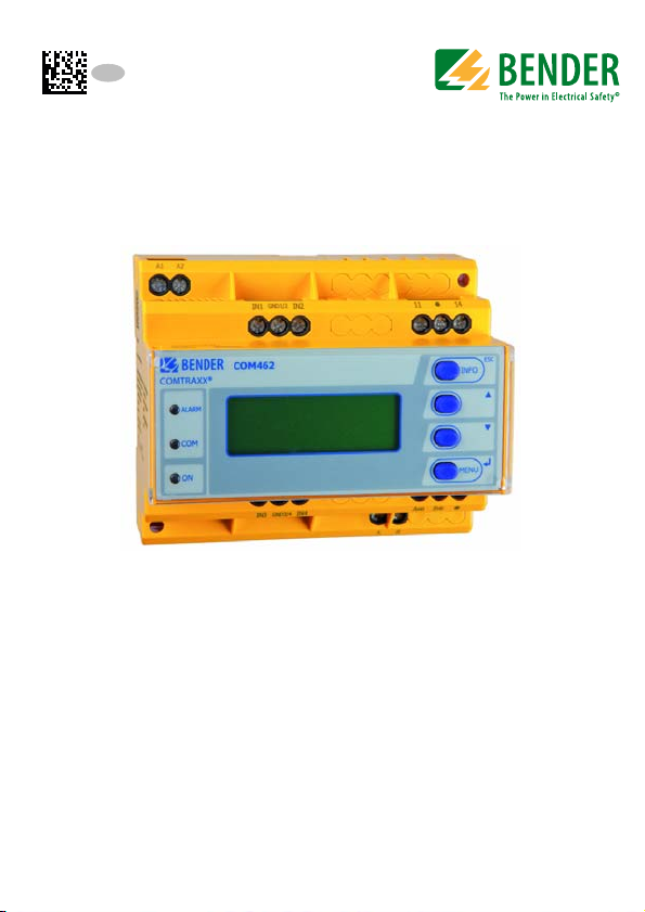
COMTRAXX® COM462RTU
BMS-Modbus RTU gateway for the connection
of BMS-capable Bender devices
to the Modbus RTU
Software version: D415 V1.2x
COM462RTU_D00010_03_M_XXEN/04.2018
Page 2

Bender GmbH & Co. KG
P.O. Box 1161 • 35301 Grünberg • Germany
Londorfer Str. 65 • 35305 Grünberg • Germany
Tel.: +49 6401 807-0 • Fax: +49 6401 807-259
E-mail: info@bender.de • www.bender.de
© Bender GmbH & Co. KG
All rights reserved.
Reprinting and duplicating only with permission of the publisher.
Subject to change!
Photos: Bender archives
Page 3

Table of Contents
1. Important information .................................................................................... 7
1.1 How to use this manual ................................................................................. 7
1.2 Technical support: Service and support .................................................. 8
1.2.1 First level support ............................................................................................. 8
1.2.2 Repair service ..................................................................................................... 8
1.2.3 Field service ........................................................................................................ 9
1.3 Training courses ................................................................................................ 9
1.4 Delivery conditions .......................................................................................... 9
1.5 Inspection, transport and storage ........................................................... 10
1.6 Warranty and liability ................................................................................... 10
1.7 Disposal ............................................................................................................ 11
1.8 Quick-start guide ........................................................................................... 11
2. Safety instructions ......................................................................................... 13
2.1 General safety instructions ........................................................................ 13
2.2 Work activities on electrical installations ............................................. 13
2.3 Intended use ................................................................................................... 14
2.4 Address setting and termination ............................................................. 14
3. Product description ....................................................................................... 15
3.1 Scope of delivery ........................................................................................... 15
3.2 Short description ........................................................................................... 15
3.3 Device features .............................................................................................. 15
3.4 Possible applications ................................................................................... 15
3.5 Details about the Modbus RTU ................................................................ 16
4. Installation, connection and commissioning ........................................... 17
4.1 Preliminary considerations ........................................................................ 17
4.2 COM462RTU on the internal BMS bus ................................................... 18
COM462RTU_D00010_03_M_XXEN/04.2018
3
Page 4

Table of Contents
4.3 Installing the device ..................................................................................... 19
4.4 Connecting the device ................................................................................ 20
4.5 Commissioning .............................................................................................. 22
5. Operation and configuration ...................................................................... 23
5.1 Display and operating elements .............................................................. 23
5.1.1 Automatic contrast setting for the display .......................................... 24
5.1.2 Display in standard mode .......................................................................... 24
5.1.3 Display in menu mode ................................................................................ 25
5.2 Factory settings .............................................................................................. 25
5.3 Settings on the device ................................................................................. 26
5.3.1 Operating example: Setting BMS address ............................................ 26
5.4 Display INFO list ............................................................................................. 28
6. Data access using Modbus RTU protocol .................................................. 29
6.1 Exception code ............................................................................................... 29
6.2 Modbus requests ........................................................................................... 30
6.3 Modbus responses ........................................................................................ 30
6.4 Structure of the exception code .............................................................. 31
6.5 Modbus address structure for BMS devices ......................................... 31
7. Modbus process image in the memory of the COM462RTU ................. 33
7.1 Querying data ................................................................................................. 33
7.1.1 Modbus function code ................................................................................ 33
7.1.2 How are the memory areas organised? ................................................ 33
7.2 Memory scheme of the process image ................................................. 35
7.2.1 BMS device address assignment on the Modbus .............................. 35
7.2.2 Memory scheme of an individual BMS device .................................... 36
7.2.3 Device type ...................................................................................................... 38
7.2.4 Timestamp ....................................................................................................... 39
7.2.5 Common alarm and device failure .......................................................... 39
7.2.6 Channels 1 to 32 with analogue and/or digital values .................... 40
7.2.6.1 Float = Floating point value of the BMS channels .................... 40
4
COM462RTU_D00010_03_M_XXEN/04.2018
Page 5

Table of Contents
7.2.6.2 AT&T = Alarm type and test type (internal/external) .............. 41
7.2.6.3 R&U = Range and unit ......................................................................... 43
7.2.6.4 Channel description ............................................................................ 45
7.2.6.5 Channel 33 to 64 ................................................................................... 46
7.3 Reference data records of the process image .................................... 47
7.3.1 Address assignment of the reference data record ............................ 47
7.3.2 Reference value on channel 1 ................................................................... 48
7.3.3 Reference value on channel 2 ................................................................... 49
7.3.4 Explanation of how to access floating point values ......................... 49
7.4 Channel descriptions for the process image ....................................... 51
7.5 Modbus control commands ...................................................................... 63
8. Technical data ................................................................................................. 67
8.1 Tabular data .................................................................................................... 67
8.2 Dimension diagram ...................................................................................... 69
8.3 Standards, approvals, certifications ........................................................ 69
8.4 Ordering details ............................................................................................. 70
9. Troubleshooting ............................................................................................ 71
9.1 Malfunctions ................................................................................................... 71
9.1.1 What should be checked? .......................................................................... 71
9.1.2 Where to find help? ...................................................................................... 71
INDEX ..................................................................................................................... 73
COM462RTU_D00010_03_M_XXEN/04.2018
5
Page 6

Table of Contents
6
COM462RTU_D00010_03_M_XXEN/04.2018
Page 7
1. Important information
DANGER
WARNING
CAUTION
1.1 How to use this manual
This manual is intended for qualified personnel working in
electrical engineering and electronics!
Always keep this manual within easy reach for future reference.
To make it easier for you to understand and revisit certain sections in this manual, we have used symbols to identify important instructions and information.
The meaning of these symbols is explained below:
This signal word indicates that there is a high risk of danger,
that will result in death or serious injury if not avoided.
This signal word indicates a medium risk of danger that can
lead to death or serious injury, if not avoided.
This signal word indicates a low-level risk that can result in
minor or moderate injury or damage to property if not
avoided.
This symbol denotes information intended to assist the user
in making optimum use of the product.
COM462RTU_D00010_03_M_XXEN/04.2018
7
Page 8

Important information
This manual has been compiled with great care. It might nevertheless contain
errors and mistakes. Bender cannot accept any liability for injury to persons or
damage to property resulting from errors or mistakes in this manual.
1.2 Technical support: Service and support
For commissioning and troubleshooting Bender offers you:
1.2.1 First level support
Technical support by phone or e-mail for all Bender products
Questions concerning specific customer applications
Commissioning
Troubleshooting
Telephone: +49 6401 807-760*
Fax: +49 6401 807-259
In Germany only: 0700BenderHelp (Tel. and Fax)
E-mail: support@bender-service.de
1.2.2 Repair service
Repair, calibration, update and replacement service for Bender products
Repairing, calibrating, testing and analysing Bender products
Hardware and software update for Bender devices
Delivery of replacement devices in the event of faulty or incorrectly
delivered Bender devices
Extended guarantee for Bender devices, which includes an in-house
repair service or replacement devices at no extra cost
Telephone: +49 6401 807-780** (technical issues)
+49 6401 807-784**, -785** (sales)
Fax: +49 6401 807-789
E-mail: repair@bender-service.de
8
COM462RTU_D00010_03_M_XXEN/04.2018
Page 9

Important information
Please send the devices for repair to the following address:
Bender GmbH, Repair-Service,
Londorfer Straße 65,
35305 Grünberg
1.2.3 Field service
On-site service for all Bender products
Commissioning, parameter setting, maintenance, troubleshooting for
Bender products
Analysis of the electrical installation in the building (power quality test,
EMC test, thermography)
Training courses for customers
Telephone: +49 6401 807-752**, -762 **(technical issues)
+49 6401 807-753** (sales)
Fax: +49 6401 807-759
E-mail: fieldservice@bender-service.de
Internet: www.bender-de.com
*Available from 7.00 a.m. to 8.00 p.m. 365 days a year (CET/UTC+1)
**Mon-Thurs 7.00 a.m. - 8.00 p.m., Fr 7.00 a.m. - 13.00 p.m.
1.3 Training courses
Bender is happy to provide training regarding the use of test equipment.
The dates of training courses and workshops can be found on the Internet at
www.bender-de.com -> Know-how -> Seminars.
1.4 Delivery conditions
Bender sale and delivery conditions apply.
COM462RTU_D00010_03_M_XXEN/04.2018
9
Page 10

Important information
For software products, the "Softwareklausel zur Überlassung von StandardSoftware als Teil von Lieferungen, Ergänzung und Änderung der Allgemeinen
Lieferbedingungen für Erzeugnisse und Leistungen der Elektroindustrie"
(software clause in respect of the licensing of standard software as part of deliveries, modifications and changes to general delivery conditions for products and services in the electrical industry) set out by the ZVEI (Zentralverband
Elektrotechnik- und Elektronikindustrie e.V.) (German Electrical and Electronic
Manufacturers' Association) also applies.
Sale and delivery conditions can be obtained from Bender in printed or electronic format.
1.5 Inspection, transport and storage
Inspect the dispatch and equipment packaging for damage and compare the
contents of the package with the delivery documents. In the event of damage
in transit, please contact Bender immediately.
The devices must only be stored in areas where they are protected from dust,
damp, and spray and dripping water, and in which the specified storage temperatures can be ensured.
1.6 Warranty and liability
Warranty and liability claims in the event of injury to persons or damage to
property are excluded if they can be attributed to one or more of the following causes:
Improper use of the device.
Incorrect mounting, commissioning, operation and maintenance of the
device.
Failure to observe the instructions in this operating manual regarding
transport, commissioning, operation and maintenance of the device.
Unauthorised changes to the device made by parties other than the
manufacturer.
Non-observance of technical data.
Repairs carried out incorrectly and the use of replacement parts or
accessories not approved by the manufacturer.
10
COM462RTU_D00010_03_M_XXEN/04.2018
Page 11

Important information
Catastrophes caused by external influences and force majeure.
Mounting and installation with device combinations not recom-
mended by the manufacturer.
This operating manual, especially the safety instructions, must be observed by
all personnel working on the device. Furthermore, the rules and regulations
that apply for accident prevention at the place of use must be observed.
1.7 Disposal
Abide by the national regulations and laws governing the disposal of this device. Ask your supplier if you are not sure how to dispose of the old equipment.
The directive on waste electrical and electronic equipment (WEEE directive)
and the directive on the restriction of certain hazardous substances in electrical and electronic equipment (RoHS directive) apply in the European Community. In Germany, these policies are implemented through the "Electrical and
Electronic Equipment Act" (ElektroG). According to this, the following applies:
Electrical and electronic equipment are not part of household waste.
Batteries and accumulators are not part of household waste and must
be disposed of in accordance with the regulations.
Old electrical and electronic equipment from users other than private
households which was introduced to the market after 13th August 2005
must be taken back by the manufacturer and disposed of properly.
For more information on the disposal of Bender devices, refer to our
homepage at www.bender-de.com -> Service & support.
1.8 Quick-start guide
Connection of the COM462RTU
If you are familiar with the installation and connection of electrical devices,
particularly with Modbus RTU, you can start right away with the wiring diagram on page 20.
It may also be helpful to refer to the block diagrams representing an application example with an internal BMS bus (BMS=Bender measuring device interface) on page 18.
COM462RTU_D00010_03_M_XXEN/04.2018
11
Page 12

Important information
Using the Modbus RTU functions
Information about this field can be found from page 29 onwards.
12
COM462RTU_D00010_03_M_XXEN/04.2018
Page 13
2. Safety instructions
DANGER
2.1 General safety instructions
Part of the device documentation in addition to this manual is the enclosed "
Safety instructions for Bender products".
2.2 Work activities on electrical installations
Only qualified personnel are permitted to carry out the
work necessary to install, commission and run a device or
system.
Risk of electrocution due to electric shock!
Touching live parts of the system carries the risk of:
An electric shock
Damage to the electrical installation
Destruction of the device
Before installing and connecting the device, make sure
that the installation has been de-energised. Observe the
rules for working on electrical installations.
If the device is used outside the Federal Republic of Germany, the applicable
local standards and regulations must be complied with. The European standard EN 50110 can be used as a guide.
COM462RTU_D00010_03_M_XXEN/04.2018
13
Page 14
Safety instructions
CAUTION
2.3 Intended use
The BMS-Modbus RTU gateway COM462RTU connects the serial Bender BMS
bus to the serial Modbus RTU. The gateway converts alarms, measured values
and statuses from the BMS bus to Modbus RTU. Control commands can be
converted from Modbus RTU to BMS bus.
This allows connection to Modbus networks. The gateway is operated on the
internal BMS bus.
2.4 Address setting and termination
In order to ensure proper functioning of the BMS-Modbus RTU gateway
COM462RTU, correct address assignment and termination of the BMS bus and
the Modbus RTU is of utmost importance.
Assigning addresses that are already used by existing devices
in the BMS or Modbus RTU networks concerned may cause
serious malfunctions.
Ensure correct address setting and termination of the COM462RTU. For details
refer to "Commissioning" on page 22.
Interface on the Modbus RTU side
The COM462RTU is always operated as slave on the Modbus
RTU side. Therefore, the COM462RTU and its Modbus RTU
has to be communicated to the Modbus RTU master.
Interface on the BMS side:
COM462RTU can be operated as master or slave.
14
COM462RTU_D00010_03_M_XXEN/04.2018
Page 15

3. Product description
3.1 Scope of delivery
You will receive:
the COM462RTU
an operating manual
3.2 Short description
The BMS-Modbus RTU gateway COM462RTU contains a Modbus RTU slave
that converts BMS data for a Modbus master.
A setting menu makes it possible to configure the COM462RTU using the setting menu (see "Commissioning" on page 22).
3.3 Device features
Setting of address data for the BMS bus and Modbus RTU and date and
time setting using the internal operating menu.
Time synchronisation for all BMS bus devices
Operation on the internal BMS bus
Modbus RTU data access to the internal BMS bus, max. 150 BMS
devices
Commands can be sent from an external application (e.g. visualisation
software) to BMS devices and measured values read.
3.4 Possible applications
The use of professional visualisation programs by converting BMS data
to Modbus RTU protocols.
Observing and analysing Bender products that support communica-
tion, such as RCMS, EDS and MEDICS® systems.
COM462RTU_D00010_03_M_XXEN/04.2018
15
Page 16

Product description
3.5 Details about the Modbus RTU
The Modbus RTU (Remote Terminal Unit) field bus has been specified by Modicon, a company under the Schneider Automation brand and made available
to the market license-free.
Modbus uses the serial hardware interface RS-485 and communicates via a
two-wire, twisted copper wire. A transmission rate of 19200 baud is s tandard.
Key data:
Master-slave communication
Up to 32 bus devices per network, or up to 247 bus devices (with
repeater)
Baud rate between 1200 and 57600 bit/s
Diagnostics mechanisms
16
COM462RTU_D00010_03_M_XXEN/04.2018
Page 17
4. Installation, connection and commissioning
DANGER
Only qualified personnel are permitted to carry out the
work necessary to install, commission and run a device or
system.
Risk of electrocution due to electric shock!
Touching live parts of the system carries the risk of:
An electric shock
Damage to the electrical installation
Destruction of the device
Before installing and connecting the device, make sure
that the installation has been de-energised. Observe the
rules for working on electrical installations.
If you are familiar with the configuration of Modbus RTU
networks, you can carry out the connection of the
COM462RTU by yourself. Otherwise please contact your
EDP administrator!
4.1 Preliminary considerations
1. Have all the questions as regards the installation been answered by the
technician responsible for the installation?
2. The device is operated on the internal bus. Is the BMS address to be set
known?
If, apart from the COM462RTU, an alarm indicator and test combination
MK800 is connected to the internal bus, the COM462RTU must not
have the address 1 (master).
You will find more detailed information on the BMS topic, in particular
about the wiring of bus devices, in the separate document "BMS bus".
COM462RTU_D00010_03_M_XXEN/04.2018
17
Page 18
Installation, connection and commissioning
COM462RTU
D+ D- D- D-D+ D+
D-D+
Modbus RTU
You can download the document from the download area of the website www.bender-de.com.
3. Is the Modbus RTU address to be set known?
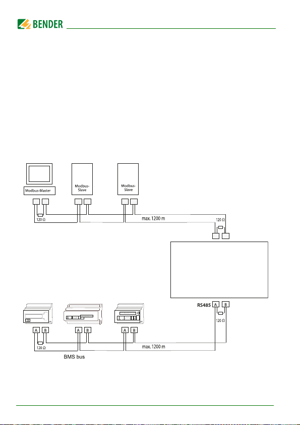
4.2 COM462RTU on the internal BMS bus
Bender systems such as EDS46x/49x, RCMS46x/49x and MEDICS communicate with each other via the Bender measuring device interface BMS.
The BMS-Modbus RTU gateway COM462RTU provides the coupling between
the BMS bus and Modbus RTU networks. The following block diagram illustrates the operation of the gateway in an internal BMS bus.
Fig. 4.1: Block diagram of a coupling between an internal BMS bus
and Modbus RTU
18
COM462RTU_D00010_03_M_XXEN/04.2018
Page 19
Installation, connection and commissioning
WARNING
Internal and external BMS bus
The majority of Bender devices communicate via the interna l
BMS bus.
Individual devices, such as MK800, TM800 or Bender panels
can communicate via both the internal BMS bus (BMS i) and
the external BMS bus (BMS e).
The BMS-Modbus RTU gateway COM462RTU can only
communicate via the internal BMS bus (BMS i).
4.3 Installing the device
Possible methods of mounting:
DIN rail mounting
Screw mounting with 2 x M4 (dimension diagram on page 69)
When installing the device, please take into consideration
that the device is only to be used in locations that are
protected from unauthorised entry! This can be installation
in a switch cabinet, for example.
COM462RTU_D00010_03_M_XXEN/04.2018
19
Page 20
Installation, connection and commissioning
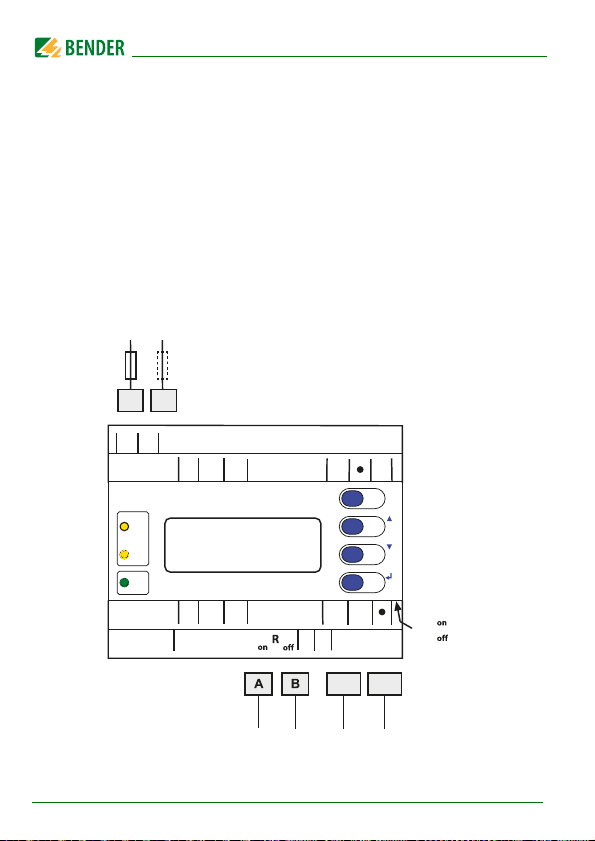
4.4 Connecting the device
For UL applications, the following is to be observed:
– Supply voltage U
– Maximum ambient temperature: 55°C
– For use in pollution degree 2 environments
– Use 60/70 °C copper lines only
– Tightening torque for terminals: 0.5…0.6 Nm
Connect the terminals and sockets on the COM462RTU according to the wiring diagram.
U
S
: see nameplate and ordering details
s
20
6 A
6 A
A1
A2
A1 A2
GND
IN2
IN1
1/2
ALARM
COM
ON MENU
GND
IN4
IN3
3/4
A
BMS-Bus
RS-485
COM462RTU_D00010_03_M_XXEN/04.2018
11
AMB
BMB
B
AMB BMB
Modbus RTU
RS-485
14
ESC
INFO
RMB
(AMB, BMB)
Page 21

Installation, connection and commissioning
Terminal Description
A1, A2
A, B
A
MB, BMB
R
on/off
(A, B)
R
MB
on/off
(A
MB, BMB)
IN1,
GND1/2,
IN2
11, 14
IN3,
GND3/4,
IN4
Connection to the supply voltage, 6 A fuse recommended,
two-pole fuses should be used in IT systems.
For UL and CSA applications, it is mandatory to use 5 A fuses.
Connection to the BMS bus (internal) with shielded cable
(e.g. J-Y(St)Y 2x0.8).
Connection Modbus RTU with shielded cable
(e.g. J-Y(St)2x0.8).
Switch for BMS bus termination. When the device is installed
at the end of the bus, set the terminating switch to "on".
Switch for Modbus RTU termination. When the device is
installed at the end of the bus, set the terminating switch to
"on".
Currently has no function (digital inputs)
Currently has no function (alarm relay K1)
Currently has no function (digital inputs)
COM462RTU_D00010_03_M_XXEN/04.2018
21
Page 22

Installation, connection and commissioning
4.5 Commissioning
1. Apply the supply voltage to the COM462RTU. The green "ON" LED
lights up.
2. Set language and time.
3. Set the BMS bus. The COM462RTU is operated on the internal BMS bus.
4. Set the Modbus RTU.
For details about the settings, refer to the chapter "Settings on the device" on
page 26.
22
COM462RTU_D00010_03_M_XXEN/04.2018
Page 23
5. Operation and configuration
1
2
3
4
5
6
7
8
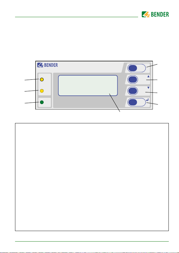
5.1 Display and operating elements
COMTRAXX®
Legend
"ON“ LED lights when supply voltage is applied.
1
"COM" LED lights when the gateway is responding to BMS
2
requests.
"ALARM“ LED, lights to signal an internal device error on the
3
COM462RTU.
"INFO" button, to query the COM462RTU for device-specific infor-
4
mation.
"ESC" button to exit the menu function without changing parameters.
5
"" button: to move up in the menu, to increase values
6
"" button: to move down in the menu, to decrease values
"MENU" button for starting and exiting the menu.
7
↵" button to confirm parameter change.
"
LC display for standard and menu mode.
8
COM462
ALARM
COM
ON MENU
COM462RTU_D00010_03_M_XXEN/04.2018
ESC
INFO
23
Page 24

Operation and configuration
5.1.1 Automatic contrast setting for the display
The display contrast control is factory set to an optimum value. In exceptional
cases, it may be necessary to adjust the contrast manually.
Press and hold the buttons "ESC" and "↵" simultaneously. All available con-
trast modes are continuously indicated in an infinite loop: minimum contrast,
maximum contrast, no contrast (lasting some seconds), then the same cycle
starts again. If the button "" is additionally pressed, the contrast modes will
be displayed in the opposite direction.
Release the button as soon as the desired level of contrast is reached.
5.1.2 Display in standard mode
Network-related parameters will be indicated.
COM462RTU
1
Address:1
2
Modbus:240
3
22.06.2013 12:34
4
Legend
Device type
1
BMS address of the COM462RTU
2
Modbus address of the COM462RTU
3
Current date and time
4
24
COM462RTU_D00010_03_M_XXEN/04.2018
Page 25

Operation and configuration
5.1.3 Display in menu mode
Use the "MENU" button to switch to the Menu mode.
Exit
1. Settings
2. Info
A blinking cursor supports menu navigation.
You can access the individual menus by means of the "" or "" but-
ton.
Press the "↵" button to confirm the selection of a menu or any setting
you changed.
To leave the respective menu level or discard a setting which is not
confirmed yet, press the "ESC" button.
Menu mode is exited if no button is pressed for longer than
five minutes.
Menu item Function Page
Exit Exit menu mode
1.Settings Make the necessary settings for this device 26
2.Info Display information on device type and
firmware versions. The same information as
indicated in the standard mode when
pressing the "INFO" button.
5.2 Factory settings
All factory settings you will find in the table on page 26.
COM462RTU_D00010_03_M_XXEN/04.2018
28
25
Page 26

Operation and configuration
5.3 Settings on the device
The menu is divided into three levels. All menu items listed in the table can be
called up via the main menu item "1. Settings" in the top menu level. All control buttons are explained on page 23.
5.3.1 Operating example: Setting BMS address
The following example shows the operating principle. All settings are carried
out in the same way.
1. Press the "MENU" button on the COM462RTU
2. Select "1. Settings" > "1. Interface" > "1. Address". The factory-set BMS
address will be displayed and can be changed now.
3. Modify the addresses using the button "" or "".
4. Confirm the modified BMS address with "↵".
Menu
level 2
Menu
level 3
Fac tor y
setting
Description
1. Interface 1. Address 2 Set the BMS address of
COM462RTU: 1…99 (internal BMS
bus)
2. Interval 2 s Set the cycle time 1…3s for the
sequence:
- Querying alarms in the BMS bus
- Querying new bus devices
- Offering the BMS master function
3. Failure
monitoring
5
Number of BMS bus cycles until a
BMS device failure is signalled. The
setting is only effective when the
COM462RTU has the master function on the BMS bus (address 1).
Adjustable cycles: 1…10
26
COM462RTU_D00010_03_M_XXEN/04.2018
Page 27

Operation and configuration
Menu
level 2
2. Modbus 1. Address 2 Set the Modbus RTU address for
3. Language
4. Clock 1. Format d.m.y Date format: m-d-y/d.m.y
5. Password
Menu
level 3
2. Baud rate 19200 Set the baud rate
3. Parity even Set the parity
4. Control off Switch on or switch off the control
1. English Deutsch Selection of the operating language
2. Deutsch
3. Français
2. Date 01.01.2010 Date
3. Time 00:00 Time
4. Summertime
1. Password 000 Enter/change password: 0…999
2. Status
Fac tor y
setting
Description
COM462RTU: 2…247
commands via Modbus
off Select Central European Summer
Time:
off = Function switched off
DST = Automatic switchover, USA,
CDN
CEST = Automatic switchover, Central Europe
on = Set time zone +1 h
off Enable/disable password protection
for parameter setting via the buttons of the COM462RTU
COM462RTU_D00010_03_M_XXEN/04.2018
27
Page 28

Operation and configuration
Menu
level 2
6. Service For authorised Bender Service personnel only.
Menu
level 3
Fac tor y
setting
Description
5.4 Display INFO list
Open the "INFO" menu:
In standard mode: press the "INFO" button or
In menu mode: select function "2. Info"
COM462RTU
Address:1
Device:B95061022
S:0123456789
This menu displays information about the device and the software. Navigate
in the list using the "" resp. the "" button.
1. Name of the device
2. BMS address
3. Order number
4. Serial number
5. Software version
6. Manufacturer's address
Please have this information to hand if you need to contact us for assistance
by telephone.
28
COM462RTU_D00010_03_M_XXEN/04.2018
Page 29

6. Data access using Modbus RTU protocol
Request to the COM462RTU are sent using the function code 0x03 (read several registers). The COM462RTU generates a function-related response and returns it.
6.1 Exception code
If a request cannot be answered for whatever reason, the COM462RTU sends
a so-called exception code with which possible faults can be narrowed down.
Exception
code
0x01
0x02
0x03
0x04
0x05
0x06
0x08
0x0A
0x0B
Description
Impermissible function
Impermissible data access
Impermissible data value
Slave device error
Acknowledgement of receipt (answer will be time-delayed)
Request not accepted (repeat request, if necessary)
Memory: Parity Error
Gateway path not available
Gateway error
COM462RTU_D00010_03_M_XXEN/04.2018
29
Page 30

Data access using Modbus RTU protocol
6.2 Modbus requests
The required words of the process image can be read from the "Holding registers" in the COM462RTU using the function code 0x03. For this purpose, the
start address and the number of the registers to be read out have to be entered.
A complete bus image including all devices and device parameters is stored
in these "Holding registers". This image represents the current statuses and
values of up to 150 BMS devices for each monitored internal BMS bus. The operating manuals of the devices indicate which channel contains which information. Example: In the table below, Words 0 and 1 are to be read out from
the "Holding registers“ 0x100 and 0x101.
Byte Name Example
Byte 0 BMS address of the COM462RTU 0x02
Byte 1 Function code 0x03
Byte 2, 3 Start address 0x01 00
Byte 4, 5 Number of registers 0x00 02
Byte 6, 7 CRC16 0x12 34
6.3 Modbus responses
The responses consist of 2 bytes per register.
Byte Name Example
Byte 0 BMS address of the COM462RTU 0x02
Byte 1 Function code 0x03
Byte 2 Number of data bytes 0x04
Byte 3…6 Information 0xAB CD 01 23
Byte 7, 8 CRC16 0x12 34
30
COM462RTU_D00010_03_M_XXEN/04.2018
Page 31

Data access using Modbus RTU protocol
6.4 Structure of the exception code
Byte Name Example
Byte 0 BMS address of the COM462RTU 0x02
Byte 1 Function code (0x03) + 0x80 0x83
Byte 2 Data 0x04
Byte 3, 4 CRC16 0x12 34
6.5 Modbus address structure for BMS devices
Function Address range
Device type 0x00…0x09 20 bytes 10 words
Timestamp 0x0A…0x0D 8 bytes 4 words
Common alarm 0x0E
No BMS bus connection
Unused 0x0F 2 bytes 1 word
Channel 1…32 0x10…0x8F 32 x 8 bytes 128 words
Alarm and test
Channel 33…64
COM462RTU_D00010_03_M_XXEN/04.2018
(high byte)
0x0E
(low byte)
0x90…0xFC 218 x 8 bytes 109 words
Number of
bytes
1 byte 0.5 words
1 byte 0.5 words
Number of
words
31
Page 32

Data access using Modbus RTU protocol
32
COM462RTU_D00010_03_M_XXEN/04.2018
Page 33

7. Modbus process image in the memory of the COM462RTU
The device holds a process image in memory. This image represents the curren t sta tuses and v alue s of u p to 15 0 BMS devices for each monitored internal
BMS bus.
7.1 Querying data
7.1.1 Modbus function code
The memory in the COM462RTU can be read using the Modbus function 0x03
(read several registers). The volume of the queried data depends on the
number of bytes selected in the Modbus client used. Up to 125 words (0x7D)
can be read with a single query.
An individual addressable byte, such as the set bit for a saved common alarm,
can also be read.
7.1.2 How are the memory areas organised?
Memory utilisation Start address
Reference values
for test purposes
Process image 0x0100 0x95FF 0x9500
Unused 0x96FF 0xFFFF 0x6900
COM462RTU_D00010_03_M_XXEN/04.2018
0x0000 0x00FF 0x0100
End of
memory area
Size of memory
area
33
Page 34

Modbus process image in the memory of the COM462RTU
In some Modbus clients, an offset of 1 must be added to the
register addresses.
Example: process image start address = 0x0101.
The assignment of the memory addresses and the associated memory content is described below.
34
COM462RTU_D00010_03_M_XXEN/04.2018
Page 35

Modbus process image in the memory of the COM462RTU
7.2 Memory scheme of the process image
7.2.1 BMS device address assignment on the Modbus
As illustrated in the table, the Modbus start address for the respective process
image is derived from the BMS device address. 256 (0x100) Words or 512 bytes
are reserved for each BMS device. They contain all the information requested
and transmitted from the bus.
Modbus address ranges of the process images in the
memory
Word
BMS
Device
address
10x01 Device 1
2 0x02 Device 2
30x03 Device 3
…… …
32 0x20 Device 32
HiByte LoByte
00 … FF
…… …
150 0x96 Device 150
Tab. 7.1: Modbus start address for each BMS device for which a request is to be
sent.
COM462RTU_D00010_03_M_XXEN/04.2018
35
Page 36

Modbus process image in the memory of the COM462RTU
7.2.2 Memory scheme of an individual BMS device
BMS devices feature various types of analogue and/or digital channels. Please
take into consideration that there are device-specific differences:
BMS devices usually feature 12 channels
MK800/TM800 supports up to 64 digital channels in the master mode
The channels 33 to 64 transmit digital messages only
Use the tables on page 35 and page 38 to determine the start address to request the following device parameters:
Device type
Timestamp
Common alarm
Device error
BMS channel
Example:
In our example, channel 2 of the device with BMS address 3 is queried. How is
the start address determined for querying the channel? In our example, the
relevant cells in the table are marked bold.
1. The first address part 0x03 (HiByte) is applied from table 7.1 for BMS
device address 3.
2. The second address part 0x14 (LoByte) is applied from table 7.2 for
channel 2. Apply number 4 from the same table for the number of
words to be queried: (0x14 to 0x17 = 0x04).
3. The start address 0x0314 is composed by HiByte and LoByte.
36
COM462RTU_D00010_03_M_XXEN/04.2018
Page 37

Modbus process image in the memory of the COM462RTU
Memory image of a BMS device
0123456789ABCDEF
LoByte
--------------------------- Device type -----------------------
0x00
Channel 1 Channel 2 Channel 3 Channel 4
0x10
Channel 5 Channel 6 Channel 7 Channel 8
0x20
Channel 9 Channel 10 Channel 11 Channel 12
0x30
Channel 13 Channel 14 Channel 15 Channel 16
0x40
Channel 17 Channel 18 Channel 19 Channel 20
0x50
Channel 21 Channel 22 Channel 23 Channel 24
0x60
Channel 25 Channel 26 Channel 27 Channel 28
0x70
Channel 29 Channel 30 Channel 31 Channel 32
0x80
--
---- Time stamp ---- C D R.
33343536373839404142434445464748495051525354555657585960616263
0x90
R. R. R. R. R. R. R. R. R. R. R. R. R. R. R. R. R. R. R. R. R. R. R. R. R. R. R. R. R. R. R. R.
0xA0
R. R. R. R. R. R. R. R. R. R. R. R. R. R. R. R. R. R. R. R. R. R. R. R. R. R. R. R. R. R. R. R.
0xB0
R. R. R. R. R. R. R. R. R. R. R. R. R. R. R. R. R. R. R. R. R. R. R. R. R. R. R. R. R. R. R. R.
0xC0
COM462RTU_D00010_03_M_XXEN/04.2018
64
37
Page 38

Modbus process image in the memory of the COM462RTU
R. R. R. R. R. R. R. R. R. R. R. R. R. R. R. R. R. R. R. R. R. R. R. R. R. R. R. R. R. R. R. R.
0xD0
R. R. R. R. R. R. R. R. R. R. R. R. R. R. R. R. R. R. R. R. R. R. R. R. R. R. R. R. R. R. R. R.
0xE0
R. R. R. R. R. R. R. R. R. R. R. R. R. R. R. R. R. R. R. R. R. R. R. R. R. R. R. R. R. R. R. R.
0xF0
Tab. 7.2: Modbus address assignment of the channels in a BMS device; Hex
representation: horizontal = units, vertical = sixteens
Abbreviations for memory contents:
C = Common alarm
D = Device lost (device failure)
R. = Reserved
A detailed description of the data formats for the device type, timestamp etc.
is given below.
7.2.3 Device type
Word
0x01 0x02 0x03 0x04 0x05 0x06 0x07 0x08 0x09
0x00
ASCII text, 10 Words/20 bytes
The device type is set by a BMS bus scan.
38
COM462RTU_D00010_03_M_XXEN/04.2018
Page 39

Modbus process image in the memory of the COM462RTU
7.2.4 Timestamp
Word 0x0A 0x0B 0x0C 0x0D
HiByte LoByte HiByte LoByte HiByte LoByte HiByte LoByte
Yea r
YY
The timestamp is set according to a datagram received from a transmitting
device.
MonthMMDayDDHourhhMinutemmSecondssReserve
d
7.2.5 Common alarm and device failure
C = Common alarm und D = Device lost (device failure)
Word 0x0E
HiByte LoByte
CD
Common alarm, 1 byte:
LSB = 0 or 1
The common alarm bit is set as soon as an alarm status from the respective
BMS device is detected.
The device error bit is set when communication with the respective BMS device is no longer possible.
Device error, 1 byte:
LSB = 0 or 1
COM462RTU_D00010_03_M_XXEN/04.2018
39
Page 40

Modbus process image in the memory of the COM462RTU
7.2.6 Channels 1 to 32 with analogue and/or digital values
Word 0x00 0x01 0x02 0x03
HiByte LoByte HiByte LoByte HiByte LoByte HiByte LoByte
Floating point value (Float) AT&T R&U
Channel
description
Every analogue BMS device channel can contain alarm messages, operating
messages, measured values, test messages and descriptive text. Both analogue and digital information can be transmitted.
AT&T = Alarm type and test type (internal/external)
R&U = Range and unit
For details on the channel description refer to chapter 7.4.
7.2.6.1 Float = Floating point value of the BMS channels
Word
HiByte LoByte HiByte LoByte
Byte
31
30
Bit
S E E E E E E E E MMMMMMMMMMMMMMMMMMMMMMM
0x00 0x01
242322
16
15
8
7
Presentation of the bit order for processing analogue measuring values according to IEEE 754
S = Sign
E = Exponent
M = Mantissa
40
COM462RTU_D00010_03_M_XXEN/04.2018
0
Page 41

Modbus process image in the memory of the COM462RTU
7.2.6.2 AT&T = Alarm type and test type (internal/external)
Bit 76543210 Meaning
Errors
Status
Test internal
Tes t e xte rn al
XXXXX000 No alarm
XXXXX001 Prewarning
00XXX010 Device error
XXXXX011 Reserved
Alarm type
XXXXX100
X X X X X 1 0 1 Alarm (red LED)
XXXXX110 Reserved
XXXXX……… Reserved
XXXXX111 Reserved
00XXXXXX No test
01XXXXXX Internal test
Tes t
10XXXXXX External test
Reserved
Alarm
Reserved
Alarm (yellow LED), e.g.
insulation fault
The alarm type is coded by the bits 0 to 2. The bits 3 and 4 are reserved and
always have the value 0. Bit 5 usually has the value 0 and represents the digital
value of the status (this column is relevant for the SMI472 only).
COM462RTU_D00010_03_M_XXEN/04.2018
41
Page 42

Modbus process image in the memory of the COM462RTU
Bit 6 or 7 is usually set when an internal or external test has been completed.
Other values are reserved. The complete byte is calculated from the sum of
the alarm type and the test type.
42
COM462RTU_D00010_03_M_XXEN/04.2018
Page 43

Modbus process image in the memory of the COM462RTU
7.2.6.3 R&U = Range and unit
Bit 76543210 Meaning
XXX00000 Invalid (init)
XXX00001 No unit
XXX00010 Ω
XXX00011 A
XXX00100 V
XXX00101 %
XXX00110 Hz
XXX00111 Baud
XXX01000 F
XXX01001 H
Unit
XXX01010 °C
XXX01011 °F
XXX01100 Second
XXX01101 Minute
XXX01110 Hour
XXX01111 Day
XXX10000 Month
X X X …………… Reserved
XXX11110 CODE
XXX11111 Reserved
X X X …………… Reserved
XXX11111 Reserved
COM462RTU_D00010_03_M_XXEN/04.2018
43
Page 44

Modbus process image in the memory of the COM462RTU
Bit 76543210 Meaning
00XXXXXX Actual value
01XXXXXX The actual value is lower
10XXXXXX The actual value is higher
11XXXXXX Invalid value
Range of validity
The units of the bits 0 to 4 are coded.
Bits 6 and 7 describe the validity range of a value. Bit 5 is reserved.
The complete byte is calculated from the sum of the unit and the range of validity.
Caution!
If the unit byte refers to CODE, the recorded value or status will result in a text
message. The content of this text message is listed in the table on page 45 or
page 51. The floating point value contains an internal CODE but no valid
measured value.
44
COM462RTU_D00010_03_M_XXEN/04.2018
Page 45

Modbus process image in the memory of the COM462RTU
30x0droW
dezi-
mal
BedeutungByte
etyBoLetyBiH
Bit1514131211109876543210
Alarme und Warnungen
0000000000000000 0 Reserviert
0000000000000001 1 Isolationsfehler
0000000000000010 2 Überlast
0000000000000011 3 Übertemperatur
0000000000000100 4 Ausfall Leitung 1
0000000000000101 5 Ausfall Leitung 2
0000000000000110 6 Isolation OP-Lampe
0000000000000111 7 Reserviert
0000000000001000 8 Ausfall Verteiler
0000000000001001 9 Sauerstoff
0000000000001010 10 Vakuum
0000000000001011 11 Narkosegas
0000000000001100 12 Druckluft 5 Bar
………………………………………… … …
7.2.6.4 Channel description
A code with the associated descriptive text is available for each channel. The
table above only shows an extract from the texts. For a complete list of the
available codes or texts refer to page 51.
COM462RTU_D00010_03_M_XXEN/04.2018
45
Page 46

Modbus process image in the memory of the COM462RTU
7.2.6.5 Channel 33 to 64
Bit 76543210 Meaning
Errors
Status
Tes t in ter nal
Tes t ext erna l
XXXXX000 No alarm
XXXXX001 Prewarning
000XX010 Device error
XXXXX011 Reserved
Alarm type
XXXXX100
XXXXX101 Alarm (red LED)
XXXXX110 Reserved
XXXXX……… Reserved
XXXXX111 Reserved
00XXXXXX No test
01XXXXXX Internal test
Te st
10XXXXXX External test
Reserved
Alarm
Reserved
Alarm (yellow LED), e.g. insu-
lation fault
The BMS channels 33 to 64 only provide digital information. The information
is coded as an alarm or message type or test type (internal, external).
The coding is similar to the data format AT&T for the channels 1 to 32, with the
exception of the additional bit 4, which is used for coding device errors, e.g.
connection faults or internal device errors.
46
COM462RTU_D00010_03_M_XXEN/04.2018
Page 47

Modbus process image in the memory of the COM462RTU
7.3 Reference data records of the process image
To make it easier to check the configuration and the Modbus RTU data access
to BMS devices, COM462RTU provides a reference data record at the virtual
BMS address 0.
A real BMS device cannot have BMS address 0!
Address 0 only serves to simulate data access.
Special features of the Modbus communication are the byte offset and the
word and byte order in the memory (Big Endian). At the end of this chapter, a
few examples of correct configuration are given, which might be helpful.
7.3.1 Address assignment of the reference data record
As shown in the following table, the Modbus start address for access to the
reference data record is derived from BMS device address 0.
Modbus addresses for reference data record
Virtual
BMS
Device
address
0
COM462RTU_D00010_03_M_XXEN/04.2018
Word
HiByte
0x00
Tab. 7.3: Start addresses for the reference data record query
00 0E 10 14
Device
type
Common
Alarm
LoByte
Channel 1 Channel 2
47
Page 48

Modbus process image in the memory of the COM462RTU
The start addresses provide the following reference values:
0x0000: TEST (device type)
0x000E: 1 (common alarm, LSB of the HiByte is set)
0x0010: 230 V undervoltage (reference value on channel 1)
0x0014: 12.34 A overcurrent (reference value on channel 2)
7.3.2 Reference value on channel 1
The following reference value is stored in this channel: 230.0 V undervoltage
Word 0x10 0x11 0x12 0x13
HiByte LoByte HiByte LoByte HiByte LoByte HiByte LoByte
0x43 0x66 0x00 0x00 0x00 0x04 0x00 0x4D
Floating point value (Float) AT&T R&U Description
230.0 No/No Volt Undervoltage
Tab. 7.4: Reference data stored in channel 1
48
COM462RTU_D00010_03_M_XXEN/04.2018
Page 49

Modbus process image in the memory of the COM462RTU
7.3.3 Reference value on channel 2
The following reference value is stored in this channel:12.34 A
Word 0x14 0x15 0x16 0x17
HiByte LoByte HiByte LoByte HiByte LoByte HiByte LoByte
0x41 0x45 0x70 0xA4 0x00 0x03 0x00 0x4A
Floating point value (Float) AT&T R&U Description
12,34 No/No Ampere Overcurrent
Tab. 7.5: Reference data stored in channel 2
7.3.4 Explanation of how to access floating point values
The test value 12.34 can be read out via Modbus RTU using Modbus function
0x03 at the address 0x0014. The test value has a size of 2 words.
Proceed as follows:
1. Determine the correct byte offset
Interpreting both words as unsigned integer values should result in the
following values:
Word 1 with address 0x14: unsigned integer value => 16709 (0x4145)
Word 2 with address 0x15: unsigned integer value => 28836 (0x70A4)
2. Determine the correct byte resp. word swap
There are four different combinations of swapping. The only correct
value is 12.34.
All swapping combinations are represented in the following table.
COM462RTU_D00010_03_M_XXEN/04.2018
49
Page 50

Modbus process image in the memory of the COM462RTU
Hex value
sequence
CORRE CT
Word
swapping
Byte
swapping
Word and byte
swapping
Word 1 Word 2 Floating
Byte 1 Byte 2 Byte 3 Byte 4
A
41
C
70
B
45
D
A4
45
A4
41
70
B
D
A
C
70
41
A4
45
C
A
D
B
D
A4
B
45
C
70
A
41
point
value
12.34
4.066E+29
3098.27
-5.21E-17
50
COM462RTU_D00010_03_M_XXEN/04.2018
Page 51

Modbus process image in the memory of the COM462RTU
7.4 Channel descriptions for the process image
Measured value
Valu e
0
1 (0x01) Insulation fault
2 (0x02) Overload
3 (0x03) Overtemperature
4 (0x04) Failure line 1
5 (0x05) Failure line 2
6 (0x06) Insul. OP light Insulation fault operating
7 (0x07)
8 (0x08) Failure distribution
9 (0x09) Failure oxygen
description
alarm message/
operating message
board
Note
theatre light
10 (0x0A) Failure vacuum
11 (0x0B) Anaesthetic gas
12 (0x0C) Compressed air 5
bar
COM462RTU_D00010_03_M_XXEN/04.2018
51
Page 52

Valu e
Modbus process image in the memory of the COM462RTU
Measured value
description
alarm message/
operating message
Note
13 (0x0D) Compressed air 10
14 (0x0E) Failure nitrogen
15 (0x0F) Failure CO2
16 (0x10) Insulation UPS Insulation fault UPS
17 (0x11) Overload UPS
18 (0x12) Converter UPS
19 (0x13) UPS fault
20 (0x14) UPS emergency
21 (0x15) UPS test run
22 (0x16) Failure air condi-
23 (0x17) Batt.op. OP-L Battery-operated operat-
24 (0x18) Batt.op. OP-S Battery-operated Sat OP
25 (0x19) Fail.norm.supply Line normal power supply
bar
operation
tioning
ing theatre light
light
52
COM462RTU_D00010_03_M_XXEN/04.2018
Page 53

Modbus process image in the memory of the COM462RTU
Measured value
Valu e
26 (0x1A) Fail.safet.supply Line safety power supply
description
alarm message/
operating message
Note
27 (0x1B) Failure UPS Line additional safety
power supply
28 (0x1C) Ins.safety supply
29 (0x1D) Fail.N conductor
30 (0x1E) Short dist. panel Short circuit distribution
board
31 (0x1F)
32 (0x20)
33 (0x21)
34 (0x22)
35 (0x23) Standby function (Measuring function
switched off (standby))
36 (0x24)
37 (0x25)
38 (0x26) Batt.op. UPS Battery operation, special
safety power supply
39 (0x27) Phase sequ. left
COM462RTU_D00010_03_M_XXEN/04.2018
53
Page 54

Valu e
Modbus process image in the memory of the COM462RTU
Measured value
description
alarm message/
operating message
Note
40 (0x28) Failure UPS Battery-supported safety
41 (0x29)
66 (0x42)
67 (0x43) Function test till: Date
68 (0x44) Service till: Date
69 (0x45) Ins.fault locat Insulation fault location
70 (0x46) Peak Fault EDS system
71 (0x47) Insulation fault Insulation resistance in Ω
72 (0x48) Current Measured value in A
73 (0x49) Undercurrent
74 (0x4A) Overcurrent
75 (0x4B) Residual current Measured value in A
76 (0x4C) Voltage Measured value in V
power supply
54
COM462RTU_D00010_03_M_XXEN/04.2018
Page 55

Modbus process image in the memory of the COM462RTU
Measured value
Valu e
77 (0x4D) Undervoltage
78 (0x4E) Overvoltage
79 (0x4F) Frequency Measured value in Hz
80 (0x50)
81 (0x51) Asymmetry
82 (0x52) Capacitance Measured value in F
83 (0x53) temperature Measured value in °C
84 (0x54) Overload Measured value in %
85 (0x55) Digital input State 0 or 1
86 (0x56) Insulation fault Impedance
description
alarm message/
operating message
Note
87 (0x57) Insulation fault Alarm from an insulation
88 (0x58) Load Measured value in %
89 (0x59) Total Hazard Cur-
rent
90 (0x5A) Inductance Measured value in H
COM462RTU_D00010_03_M_XXEN/04.2018
fault locator
THC
55
Page 56

Valu e
Modbus process image in the memory of the COM462RTU
Measured value
description
alarm message/
operating message
Note
97 (0x61) Service code Information about service
101 (0x65) Connection system
102 (0x66) Connection earth
103 (0x67) Short-circuit trans-
former
104 (0x68) No CT connected
105 (0x69) Short temp.sensor Temperature sensor
106 (0x6A) Temp.sensor open. Connection temperature
107 (0x6B) K1 Fault contactor K1
108 (0x6C) K2 Fault contactor K2
109 (0x6D)
56
intervals
CT short circuit
short-circuit
sensor
COM462RTU_D00010_03_M_XXEN/04.2018
Page 57

Modbus process image in the memory of the COM462RTU
Measured value
Valu e
110 (0x6E)
111 (0x6F) No address: Failure BMS device
112 (0x70)
113 (0x71) Failure K1/Q1 Failure contactor K1/Q1
114 (0x72) Failure K2/Q2 Failure contactor K2/Q2
115 (0x73) Device error Fault ISOMETER
116 (0x74) Manual mode K1/2 manual mode
117 (0x75) Open circuit K1on Line to K1 on interrupted
118 (0x76) Open circ. K1off Line to K1 off interrupted
119 (0x77) Open circuit K2 on Line to K2 on interrupted
120 (0x78) Open circ. K2 off Line to K2 off interrupted
121 (0x79) K/Q1on Fault
description
alarm message/
operating message
Note
122 (0x7A) K/Q1off Fault
123 (0x7B) K/Q2on Fault
124 (0x7C) K/Q2off Fault
125 (0x7D) Failure K3
COM462RTU_D00010_03_M_XXEN/04.2018
57
Page 58

Modbus process image in the memory of the COM462RTU
Measured value
Valu e
126 (0x7E) Q1 Fault
127 (0x7F) Q2 Fault
128 (0x80) No master
129 (0x81) Device error
130 (0x82)
131 (0x83) Fault RS-485
132 (0x84)
133 (0x85)
134 (0x86)
135 (0x87)
136 (0x88)
137 (0x89) Short circuit Q1
description
alarm message/
operating message
Note
138 (0x8A) Short circuit Q2
139 (0x8B) CV460 CV460 fault
140 (0x8C) RK4xx Fault RK4xx
58
COM462RTU_D00010_03_M_XXEN/04.2018
Page 59

Modbus process image in the memory of the COM462RTU
Measured value
Valu e
description
alarm message/
operating message
Note
141 (0x8D) Address collision BMS address has been
142 (0x8E) Invalid address
143 (0x8F) Several masters
144 (0x90) No menu access
145 (0x91) Own address
201 (0xC9) Line 1 normal op
202 (0xCA) Line 2 normal op
203 (0xCB) Switch. el. 1 on
204 (0xCC) Switch. el. 2 on
205 (0xCD)
206 (0xCE) Auto mode
207 (0xCF) Manual mode
208 (0xD0)
assigned several times
COM462RTU_D00010_03_M_XXEN/04.2018
59
Page 60

Modbus process image in the memory of the COM462RTU
Measured value
Valu e
209 (0xD1)
210 (0xD2) Line AV on
211 (0xD3) Line SV on
212 (0xD4) Line UPS on
213 (0xD5) Channel disabled
description
alarm message/
operating message
Note
214 (0xD6) switching back
interlocking function
215 (0xD7) Phase sequ. right
216 (0xD8) Switch. el. pos.0
217 (0xD9) Line BSV on
218 (0xDA) On SMO48x: Alarm, relay
60
Switching back interlocking function enabled
COM462RTU_D00010_03_M_XXEN/04.2018
Page 61

Modbus process image in the memory of the COM462RTU
To convert parameter data, data type descriptions are required. Text representation is not necessary in this case.
Value Description of parameters
1023 (0x3FF) Parameter/measured value invalid.
1022 (0x3FE) No measured value/no message
1021 (0x3FD) Measured value/parameter inactive
1020 (0x3FC) Measured value/parameter only temporarily inactive
1019 (0x3FB) Parameter/measured value (value) unit not displayed
1018 (0x3FA) Parameter (code selection menu) unit not displayed
1017 (0x3F9) String max. 18 characters (e.g. device type, - variant, …)
1016 (0x3F8)
1015 (0x3F7) Time
1014 (0x3F6) Date: Day
1013 (0x3F5) Date: Month
1012 (0x3F4) Date: Year
1011 (0x3F3) Register address (unit not displayed)
1010 (0x3F2) Time
The menu item of this parameter is not displayed.
(e.g. during the transfer of a new parameter) Display in
the menu "…".
COM462RTU_D00010_03_M_XXEN/04.2018
61
Page 62

Modbus process image in the memory of the COM462RTU
Value Description of parameters
1009 (0x3F1) Factor multiplication [*]
1008 (0x3F0) Factor division [/]
1007 (0x3EF) Baud rate
62
COM462RTU_D00010_03_M_XXEN/04.2018
Page 63

Modbus process image in the memory of the COM462RTU
7.5 Modbus control commands
Commands can be sent to BMS devices by an external application (e.g. visualisation software).
Control via Modbus can be enabled or disabled in the browser menu "1. Settings" > "2. Modbus" > "4. Control".
Command structure (example)
Example: system setup:
BMS addr. 1 COM460IP
BMS addr. 2 COM462RTU (Modbus addr. 2)
BMS addr. 4 IRDH275
Request:
Byte Name Example
Byte 0 Modbus address of the COM462RTU 02
Byte 1 Function code 10
Byte 2, 3 Start register FC 00
Byte 4, 5 Number of registers 00 04
Byte 6 Number of bytes 08
Byte 7, 8 External address:
must always be "1" for COM462RTU.
Byte 9, 10 The internal BMS address to which the com-
mand applies.
Byte 11, 12 Channel 00 00
Byte 13, 14 Control command 00 01
Byte 15, 16 CRC16 Checksum 84 86
00 01
00 04
COM462RTU_D00010_03_M_XXEN/04.2018
63
Page 64

Modbus process image in the memory of the COM462RTU
Answer:
Byte Name Example
Byte 0 Modbus address of the COM462RTU 02
Byte 1 Function code 10
Byte 2, 3 Start register FC 00
Byte 4, 5 Number of registers 00 04
Byte 6, 7 CRC16 Checksum F1 A9
Register addresses for writing. function code write: 0x10
0xFC00: Ext. address.
0xFC01: Int. address.
0xFC02: Channel
0xFC03: Control command
Writing to register:
Use the COM462RTU's address.
Use function code 0x10 (write several registers).
Start address in the register: 0xFC00
Number of registers: 4
Number of bytes: 8
External address: must always be "1" for COM462RTU.
The internal BMS address to which this control command applies.
Channel number
Control command
CRC16 Checksum
64
COM462RTU_D00010_03_M_XXEN/04.2018
Page 65

Modbus process image in the memory of the COM462RTU
Register addresses for reading. Function code read: 0x03
0xFC00: Ext. address.
0xFC01: Int. address.
0xFC02: Channel
0xFC03: Control command
0xFC04: Status
Reading out register:
To read, use function code 0x03 (read several registers).
Possible response in "Status" register:
0 Busy Processing command.
1 Error An error has occurred.
2 Ready Command has been processed suc-
cessfully.
Control commands for the internal BMS bus:
Register
Ext
Register
Int
Register
channel
Register
control
command
Func tion
1 1-150 0 1 Test Isometer
11-1500 2Test changeover
device PRC
1 1-150 0 3 Start automatic test
changeover
1->2. End after time
T(test)
1 1-150 0 4 Start test generator
without changeover
COM462RTU_D00010_03_M_XXEN/04.2018
65
Page 66

Modbus process image in the memory of the COM462RTU
Register
Ext
11-1500 5Switchover to line 1
11-1500 6Switchover to line 2
1 0 0 7 RESET alarm (broad-
1 0 0 8 RESET alarm EDS
1 1-150 0 9 Buzzer off [for alarm
1 1-150 1-12 10 Switch on relay/
1 1-150 1-12 11 Switch off relay/
Register
Int
Register
channel
Register
control
command
Func tion
cast)
(broadcast)
address] (BC)
switch
switch
66
COM462RTU_D00010_03_M_XXEN/04.2018
Page 67

8. Technical data
( )* = factory settings
8.1 Tabular data
Insulation coordination acc. to IEC 60664-1
Rated insulation voltage .................................................................................................................................. AC 250 V
Rated impulse withstand voltage/pollution degree .......................................................................................... 4 kV/3
Supply voltage
Supply voltage U
Frequency range U
Power consumption ....................................................................................................................... See ordering details
LED indicators
ALARM ........................................................................................................................................... internal device error
COM ................................................................................................................................................ data traffic BMS bus
ON ..................................................................................................................................................... operation indicator
Interfaces
BMS bus internal:
Interface/protocol.................................................................................................................. RS-485/BMS bus internal
Operating mode........................................................................................................................... master/slave (slave)*
Baud rate BMS internal.................................................................................................................................... 9.6 kbit/s
Cable length ....................................................................................................................................................≤ 1200 m
Cable (twisted pairs, shielded, shield connected to PE on one side)........................... recommended: J-Y(St)Y 2x0.8
Connection, BMS internal ........................................................................................................................ terminals A, B
Terminating resistor................................................................................................................................120 Ω (0.25 W)
Device address, BMS bus internal .............................................................................................................. 1…99 (2)*
Modbus RTU:
Interface/protocol..........................................................................................................................RS-485/Modbus RTU
Operating mode....................................................................................................................................................... slave
Baud rate Modbus RTU....................................................................................................................... 9.6…57.6 kbit/s
Cable length ....................................................................................................................................................≤ 1200 m
............................................................................................................................ See ordering details
s
......................................................................................................................... See ordering details
s
COM462RTU_D00010_03_M_XXEN/04.2018
67
Page 68

Technical data
Cable (twisted pairs, sh ielded, shield connected to PE on one side) ........................... recommended: J-Y(St)Y 2x0.8
Connection, Modbus RTU ....................................................................................................................terminals D+, D-
Terminating resistor................................................................................................................................120 Ω (0.25 W)
Device address, Modbus RTU ................................................................................................................... 2…247 (2)*
Environment/EMC)
EMC .............................................................................................................................................................. EN 61326-1
Classification of climatic conditions acc. to IEC 60721:
Stationary use (IEC 60721-3-3) ....................................................... 3K5 (except condensation and formation of ice)
Transport (IEC 60721-3-2) ...................................................................................................................................... 2K3
Long-term storage (IEC 60721-3-1)........................................................................................................................ 1K4
Operating temperature............................................................................................................................ -10…+55 °C
Classification of mechanical conditions acc. to IEC 60721:
Stationary use (IEC 60721-3-3)............................................................................................................................... 3M4
Transport (IEC 60721-3-2) ..................................................................................................................................... 2M2
Long-term storage (IEC 60721-3-1) ...................................................................................................................... 1M3
Connection
Connection type ............................................................................................................................ screw-type terminals
Connection properties:
Rigid/flexible............................................................................................... 0.2…4/0.2…2.5 mm
2
(AWG 24…12)
Multi-conductor connection (2 condu ctors with the same cross section):
Rigid/flexible........................................................................................................................ 0.2…1.5/0.2…1.5 mm
Stripping length ............................................................................................................................................. 8…9 mm
Tightening torque ..................................................................................................................................... 0.5…0.6 Nm
General data
Operating mode ........................................................................................................................... Continuous operation
Mounting............................................................................................................................................... display oriented
Degree of protection, internal components (IEC 60529) ....................................................................................... IP30
Degree of protection, terminals (IEC 60529) ......................................................................................................... IP20
Type of enclosure .....................................................................................................................................................X460
Screw mounting ................................................................................................................................................... 2 x M4
DIN rail mounting acc. to................................................................................................................................. IEC 60715
Flammability class ............................................................................................................................................ UL94V-0
Weight ................................................................................................................................................................≤ 310 g
2
68
COM462RTU_D00010_03_M_XXEN/04.2018
Page 69

Technical data
Option "W" data different from the standard version
Classification of climatic conditions acc. to IEC 60721:
Stationary use (IEC 60721-3-3) .................................................... 3K5 (condensation and formation of ice possible)
8.2 Dimension diagram
93
8.3 Standards, approvals, certifications
For information about UL applications refer to page 20.
COM462RTU_D00010_03_M_XXEN/04.2018
69
Page 70

Technical data
Other interface protocols
Connection to SCADA systems (Supervisory Control and Data Acquisition)
and/or PLCs via OPC, BACnet or other protocols on request.
8.4 Ordering details
Typ e
COM462RTU
BMSModbus RTU
Gateway
COM462RTUW
BMSModbus RTU
Gateway
* Absolute values
Supply voltage/
frequency range
U
S
AC/DC 76…276 V */
AC 42…460 Hz/DC
For UL application:
US AC = 76…250 V,
40…150 mA,
42…460 Hz
US DC = 76…250 V,
10…35 mA
AC/DC 76…276 V */
AC 42…460 Hz/DC
Power
consumption
3.5…40 VA,
2.4 W
3.5…40 VA,
2.4 W
UL:
Approval
available
Lloyds
Approval
available
Lloyds
Approval
available
:
:
Art.
No.
B 9506
1022
B 9506
1022W
Option W
Devices with the suffix "W“ feature increased shock and vibration resistance.
The electronics is covered with a special varnish to provide increased protection against mechanical stress and moisture. This particular feature permits
the use in ships, on rolling stock and also in seismic environment.
70
COM462RTU_D00010_03_M_XXEN/04.2018
Page 71

9. Troubleshooting
9.1 Malfunctions
If the COM462RTU causes malfunctions in the connected networks, please refer to this operating manual.
9.1.1 What should be checked?
Check whether…
the device is supplied with the correct supply voltage.
the BMS bus cable is correctly connected and terminated (120 Ω).
the Modbus RTU cable is correctly connected and terminated (120 Ω).
the BMS address is set correctly.
The Modbus RTU address is correctly set and communicated to the
master.
9.1.2 Where to find help?
If, despite thorough study of the technical manual and intensive troubleshooting in your installation, you cannot rectify the fault related to the BMSModbus RTU gateway COM462RTU, please contact our Service department
(refer to page 8).
COM462RTU_D00010_03_M_XXEN/04.2018
71
Page 72

Troubleshooting
72
COM462RTU_D00010_03_M_XXEN/04.2018
Page 73

INDEX
A
Address setting
- BMS address
- Modbus RTU address
Addressing
Application with an internal BMS bus
B
BMS bus 11
BMS device address assignment on the
Modbus
Button
- down
- INFO
- MENU
- UP
Byte offset
Byte or word swapping
C
Clock setting 27
COM462RTU on the internal BMS bus
Commissioning
D
Dimension diagram 69
Display and operating elements
Display in menu mode
Display in standard mode
26
27
14
35
23
23
23
23
49
49
22
23
25
24
18
18
E
Exception code 29
F
Factory settings 25
I
Intended use 14
L
LED
- ALARM
23
- COM
23
M
Main menu 25
Malfunctions
Measured value descriptions for the process
Memory image of a BMS device
Memory scheme of the process image
Menu overview of the functions adjustable
Modbus
71
image, list
51
37
at the device
- Address structure for BMS devices
- control commands
- function code
- Process image
- requests
26
63
33
33
30
35
31
COM462RTU_D00010_03_M_XXEN/04.2018
73
Page 74

- responses 30
O
Ordering details 70
P
Process image 35
Product description
Q
Quick-start guide 11
R
Reference data records of the process image
47
S
Scope of delivery 15
Setting the date
Support
T
Technical data 67
Termination
Termination of the BMS bus
Time setting
Training courses
Troubleshooting
15
27
71
14
21
27
9
71
Work activities on electrical installations
Workshops
9
13
U
UL applications, restrictions 20
W
Wiring diagram 20
74
COM462RTU_D00010_03_M_XXEN/04.2018
Page 75

Page 76

Bender GmbH & Co. KG
P.O. Box 1161 • 35301 Grünberg • Germany
Londorfer Str. 65 • 35305 Grünberg • Germany
Tel.: +49 6401 807-0 • Fax: +49 6401 807-259
E-mail: info@bender.de • www.bender.de
Photos: Bender archives.
BENDER Group
 Loading...